

Page 1
I & M 6800HP Series
3170 Wasson Road • Cincinnati, OH 45209 USA
Phone 513-533-5600 • Fax 513-871-0105
lowfl[email protected] • www.lowflowvalve.com
Installation & Maintenance Instructions for
Mark 6800HP High Pressure Regulators
Warning: Low Flow Regulators must only be used, installed and repaired in accordance with these Installation &
Maintenance Instructions. Observe all applicable public and company codes and regulations. In the event of leakage or other malfunction, call a qualified service person; continued operation may cause system failure or a general
hazard. Before servicing any valve, disconnect, shut off, or bypass all pressurized fluid. Before disassembling a
valve, be sure to release all spring tension.
Please read these instructions carefully!
should be exercised to prevent pipe sealing compound from getting into the pipe lines. Pipe sealing
Your LowFlow/Jordan product will provide you with long, troublefree service if it is correctly installed and maintained. Spending a few
minutes now reading these instructions can save hours of trouble and
downtime later. When making repairs, use only genuine LowFlow Valve
parts, available for immediate shipment from the factory.
compound should be used sparingly, leaving the
two lead threads clean. Jordan Valve uses, and
recommends, thread sealer Teflon ribbon.
4. A line strainer should be installed on the inlet side
of the regulator to protect it from grit, scale, and
other foreign matter. A 0.033 perforated screen is
usually suitable. Line strainers are available from
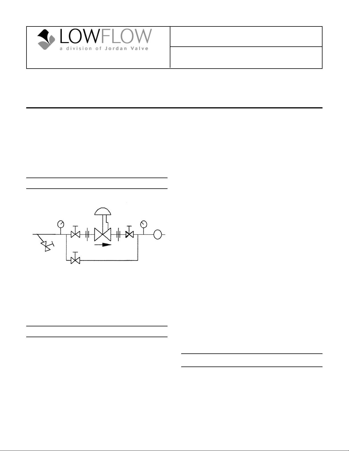
Ideal Installation Schematic
Jordan Valve.
5. The flow arrow on the valve body must be pointed
in the direction of the flow. The regulator may be
installed vertically or horizontally without affecting
its operation.
6. For best control, 3'0" straight sections of pipe
should be installed on either side of the regulator.
7. In hot vapor lines, upstream and downstream
Main Line
5
4
1
2
2
4
1
6
R
piping near the regulator should be insulated to
1
Bypass Line
minimize condensation.
8. If possible, install a relief valve downstream from
the regulator. Set at 15 psi above the control point
of the regulator.
1. Shut-off valve
2. Pipe union
3. Strainer/drainer valve
4. Pressure gauge
5. Jordan regulator
6. Relief valve
9. In gas service, expand the outlet piping at least
one pipe size, if the control pressure (downstream)
is 25% of the inlet pressure or less. A standard
tapered expander connected to the outlet of the
valve is recommended.
10. Where surges are severe, a piping accumulator is
recommended.
Preferred Installation
11. Operate the regulator within its rated pressure and
temperature.
1. To protect the valve from grit, scale, thread chips
and other foreign matter, ALL pipelines and piping
components should be blown out and thoroughly
Start-Up
cleaned before the installation process begins.
2. Shutoff valves, pressure gauges and by-pass piping
should be installed as indicated in the Ideal Instal-
lation Schematic to provide easier adjustment,
operation and testing.
3. When preparing threaded pipe connections, care
With inlet, outlet, and by-pass shutoff valves closed,
and no pressure the downstream line:
1. Fully open the outlet shutoff valve.
2. Slowly open the inlet shutoff valve.
3. Slowly open and close the outlet shutoff valve
Page 2

several times. This fully strokes the valve to insure
satisfactory operation.
4. With the outlet shutoff valve open, slowly screw
down the adjusting screw until the desired pressure
is shown on the outlet pressure gauge.
5. To change the controlled pressure, turn the adjusting screw clockwise to increase the pressure,
counter-clockwise to decrease pressure.
Warning: Never substitute a longer length adjusting
screw. Personal injury and/or damage to the valve may
result.
Maintenance
Caution: Make certain that there is no pressure in the
valve before loosening any fittings or joints. The following steps are recommended:
1. Close the inlet shutoff valve.
2. Allow pressure to bleed off through the downstream
piping. Do not attempt to reverse the flow through
the valve by bleeding pressure from the upstream
side of the valve.
3. When the pressure gauges indicate that all pressure
has been removed from the system, close the outlet
shutoff valve, and the valve may be serviced.
Valve Disassembly
1. Load the range spring by turning adjusting screw
(28) clockwise at least five full turns. This will help
prevent damaging the seat during disassembly.
2. Remove the bottom cap (1).
3. Remove the trim subassembly and the return spring
(3) from the bottom cap (1).
4. Remove the o-ring (5) and the back-up rings (4)
from the bottom cap (1).
5. Unthread the seat retainer (8) from the guide (2).
Remove the o-ring (14).
6. For valves with balanced trim, remove the o-ring (35)
and back-up rings (36) from the guide.
7. Remove the retaining ring (7) from the stem (12) and
disassemble the stem and seat (10) from the seat
retainer (8).
8. Unload the range spring by turning the adjusting
screw (28) counter-clockwise.
9. Remove the eight socket head cap screws (24) and
remove the spring housing (13).
10. Remove the upper spring guide (26), the range
spring (25), the lower spring guide (23) and the ball
bearing (22).
11. Remove the cylinder (18) from the body (6) and
remove the piston (19) from the cylinder.
12. Remove the o-rings (20 & 17) and the back-up
rings (16 & 21) from the piston (19) and cylinder
(18).
13. Remove the orifice (11) from the body (6). Remove
the o-ring (15) from the orifice.
Valve Assembly
1. Lubricate and place o-ring (15) into the groove on
the orifice (33) being careful not to cut o-ring on
threads.
2. Apply Loctite No. 242 to threads and install orifice
(11) into body. Torque to 25 ft-lbs.
3. Lubricate and place o-ring (17) with two back-up
rings (16) into the groove on the piston (19).
4. Lubricate and place o-ring (20) with two back-up
rings (21) into groove on the cylinder (18).
5. Insert the piston (19) through the chambered side
of the cylinder (18) just enough to compress the
o-ring on the piston. The end of the piston with the
o-ring should go into the cylinder first.
6. Install the cylinder (18) into the body (6).
7. Drop the ball (22) into the piston (19).
8. Install the lower spring guide (23) (into the piston
(19)). Push the piston into the cylinder until the
lower spring guide seats against the cylinder.
9. Place the range spring (25) onto the lower spring
guide (23).
10. Place the upper spring guide (26) onto the range
spring (25).
11. Install the spring housing (13) onto the body with
eight socket head cap screws (24). The spring
housing should pilot squarely onto the cylinder.
Torque the screws to 32 ft-lbs. See torque sequence diagram under Torquing Procedures.
12. Thread the hex jam nut (27) onto the adjusting
screw (28).
13. Place the shims onto the adjusting screw (28) and
thread it into the spring housing (13) until it makes
contact with the upper spring guide (inside the
spring housing). Use the same shims that were
originally installed on the valve. Do not alter the
thickness or the valve may fail to operate properly.
14. Thread the adjusting screw (28) into the spring
housing (13) until it just makes contact with the upper spring guide (inside the spring housing).
15. Load the range spring by turning the adjusting
screw clockwise five full turns. This step is important in preventing damage to the seat while installing the bottom cap and trim in the next section.
-2-
Page 3
Trim
Troubleshooting
1. Lubricate and place the o-ring (5) and two back-up
rings (4) into the groove on the bottom cap (1) being careful not to cut the o-ring on the threads.
2. Place the return spring (3) into the bottom cap (1).
3. Lubricate and insert the o-ring (9) into the seat
retainer (8).
4. Insert the seat (10) into the seat retainer (8).
5. Install the stem (12) through the seat (10) and seat
retainer (8). Secure in place with retaining ring (7).
6. Lubricate and place the o-ring (14) into the groove
on the guide (2) being careful not to cut the o-ring
on the threads. If the valve has balanced trim, lubricate and place the o-ring (35) and two back-up
rings (36) into the groove on the guide (2).
7. Apply Loctite No. 242 onto the threads of the guide
(2) and thread into the seat retainer (8). Tighten
the seat retainer until it is seated firmly against the
guide.
8. Place the completed trim subassembly into the
bottom cap (1). The stem (12) should be facing
out.
9. Apply Loctite No. 242 onto the threads of the bottom cap (1) and thread into the body (6). The stem
(12) should locate into the hole in the bottom of
the piston (19). Tighten the bottom cap until it is
seated firmly against the stop in the body.
Symptom Possible Cause and Cure
• Erratic Control
1. Oversizing causes cycling and hunting and reduces
the rageability of the valve. Make certain that your
sizing is correct.
2. Safety valve may be jammed open. Repair as
necessary.
3. Excessive foreign matter on seat (10) or orifice
(11). Clean them. Inspect seating surfaces for
deterioration.
4. Valve trim may not be moving freely. Check for any
parts that may be binding.
• Downstream Pressure Build-Up
1. Seats deteriorated. Replace.
2. Inspect for foreign matter between the seat (10) and
orifice (11).
3. Metal hard seat not supplying tight enough shutoff.
Consider using soft seat.
4. O-ring (9, 14 or 15) not sealing. Replace.
• Cannot Maintain Regulated Pressure
1. Inlet pressure too low.
2. Clogged strainer or lines. Clean.
3. Spring (25) set too low or broken. Reset or replace.
4. Valve is undersized for rated flow. Recheck sizing.
5. System demand exceeds capacity. Recheck sizing.
Torque Procedures
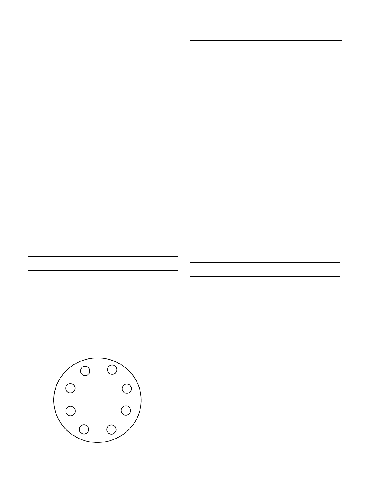
1. Install all bolts hand-tight.
2. Torque the bolts in order of the bolt pattern to a
value equal to 1/4 of the recommended torque
value.
3. Restore each bolt to 32 ft-lbs using the same bolt
pattern as shown.
Bolt Pattern/Torque Sequence
(8 bolts or multiples)
3
7
5
1
+
2
6
8
4
Low Flow Valves are ruggedly built, carefully assembled
to accurate dimensions, and individually tested for performance. A complete stock of finished parts is maintained ready for immediate shipment.
If desired, Low Flow Valve will promptly repair your
regulator at a reasonable cost. To return a valve for
inspection and/or repair, please contact our customer
service department for a Return Authorization Number.
Phone toll-free at 1-800-543-7311. If preferred, you may
fax us at 513-871-0105.
When ordering spare parts, first make a note of the following information on the valve's nameplate:
• serial number
• model number and size
• body material and end connections
• range
• seat and seal materials
Troubleshooting
-3-
Page 4
25
24
23
22
21
20
19
18
17
16
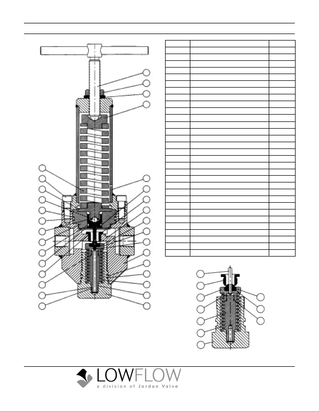
Cross Section View
Item No. Description Quantity
1 Body Cap 1
2 Guide 1
3 Spring 1
28
27
42
26
13
12
11
10
9
8
7
6
5
4* Back-Up Ring 2
5* O-Ring 1
6 Body 1
7* Retaining Ring 1
8* Seat Retainer 1
9* O-Ring 1
10* Seat 1
11* Orifice 1
12* Stem 1
13 SpringHousingSubassembly 1
14* O-Ring 1
15* O-Ring 1
16* Back-Up Ring 2
17* O-Ring 1
18 Cylinder 1
19 Piston 1
20* O-Ring 1
21* Back-Up Ring 2
22 Ball Bearing 1
23 Lower Spring Guide 1
24 SocketHeadCapScrew 8
25 Spring 1
26 Upper Spring Guide 1
27 HexJamNut 1
28 Adjusting Screw Subassembly 1
35* O-Ring 1
36* Back-Up Ring 2
42* Shim 1
* Recommended Spare Parts
15
14
36
35
BulletinIM-6800HP-0511
Balanced Trim
4
3
2
1
12
11
8
7
2
10
9
14
3
1
Un-Balanced Trim
3170WassonRoad•Cincinnati,OH45209USA
Phone513-533-5600•Fax513-871-0105
low[email protected]•www.lowowvalve.com
 Loading...