

Page 1
I & M 5800HP/5850HP Series
3170 Wasson Road • Cincinnati, OH 45209 USA
Phone 513-533-5600 • Fax 513-871-0105
lowfl[email protected] • www.lowflowvalve.com
Warning: Low Flow Regulators must only be used, installed and repaired in accordance with these Installation &
Maintenance Instructions. Observe all applicable public and company codes and regulations. In the event of leakage or other malfunction, call a qualified service person; continued operation may cause system failure or a general
hazard. Before servicing any valve, disconnect, shut off, or bypass all pressurized fluid. Before disassembling a
valve, be sure to release all spring tension.
Please read these instructions carefully!
Your LowFlow/Jordan product will provide you with long,
trouble-free service if it is correctly installed and maintained. Spending a few minutes now reading these instructions can save hours of trouble and downtime later.
When making repairs, use only genuine LowFlow Valve
parts, available for immediate shipment from the factory.
Installation & Maintenance Instructions for
Mark 5800HP & Mark 5850HP Regulating Valves
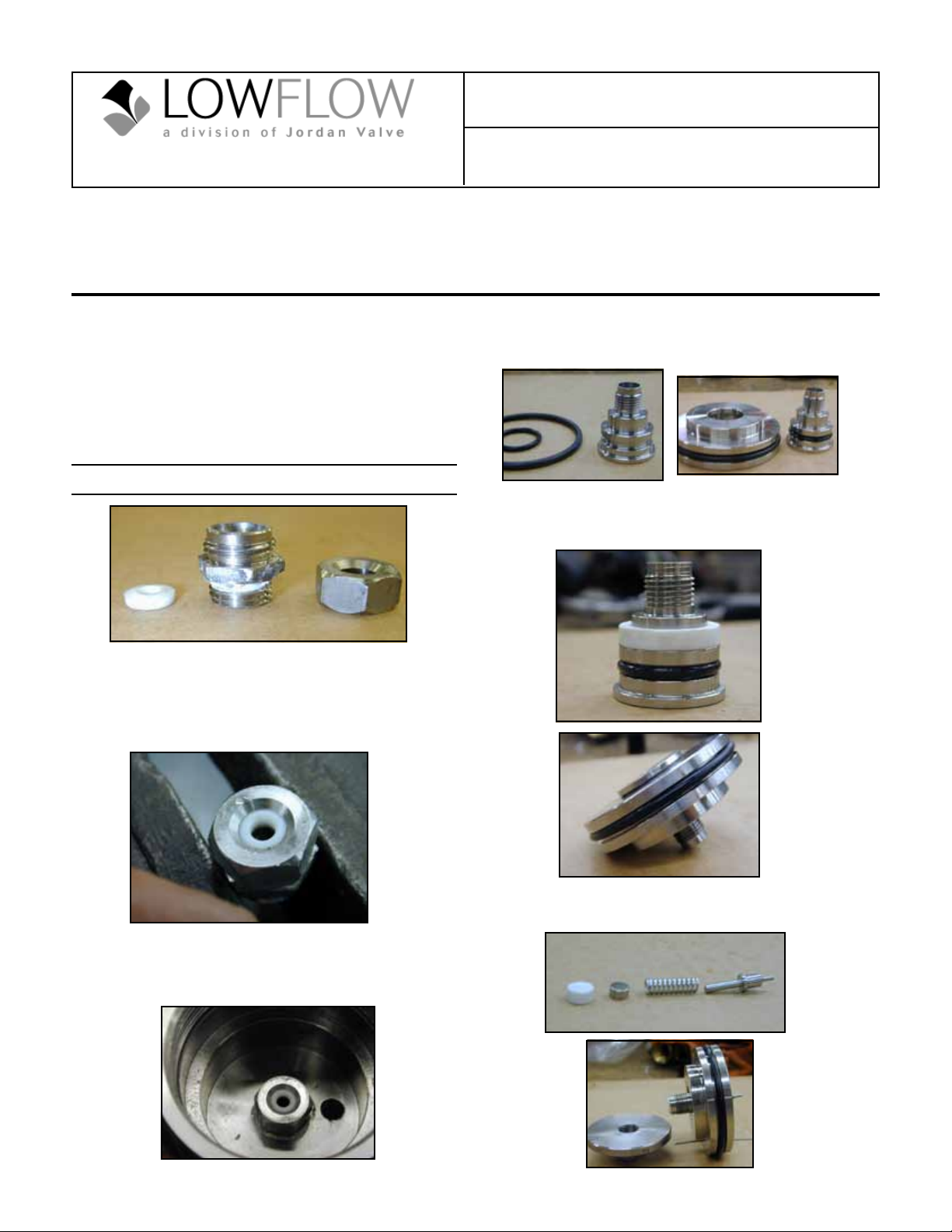
6. Lube the piston and cylinder o-rings with Dow
Corning grease.
7. Assemble the o-rings to the mating parts.
Assembly Instructions
8. Install the Teflon piston bushing onto the piston.
9. Slide the piston into the cylinder as shown, being
careful not to damage the o-ring.
1. Inspect the Teflon soft seat insert. There can be no burrs,
cuts, or scratches in the ID sealing area of the insert.
2. Install the soft seat insert into the orifice.
3. Thread the seat cap on top of the insert and tighten
securely.
4. Apply liquid Teflon (Loctite 567) to the exposed
threads of the seat assembly.
5. Assemble the seat assembly into the body and
torque to 200 in-lbs.
10. Install the plug, plug spring, follower, and stem seal
into the piston in order as shown below.
Page 2
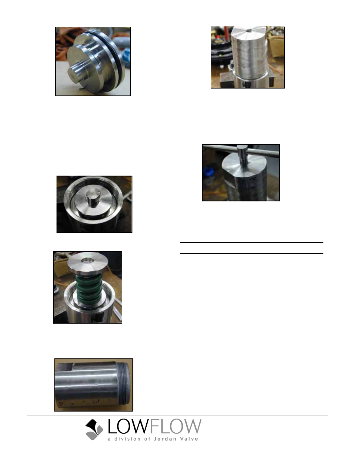
11. Thread the lower spring guide onto the piston and
tighten securely. You will have to compress the stem
seal when tightening.
12. Place the cylinder assembly into the body with the
plug pointed towards the seat. You must be very
careful not to damage the cylinder o-ring on the
threads of the body.
13. Using pressure from your ngers, press the cylinder
assembly all the way into the counterbore. You may
have to work from side to side to get this properly
seated.
14. Install the spring and upper spring guide onto the
lower spring guide.
15. Use anti-seize and generously coat the spring housing threads.
16. Assemble the spring housing into the body and
tighten with a pipe wrench securely.
17. Lubricate all of the adjusting screw threads with
anti-seize.
18. Thread the jamnut onto the adjusting screw.
19. Slide the nametag onto the threads.
20. Thread the adjusting screw assembly into the spring
housing until you can feel the range spring start to
compress.
21. If not already done, stamp “inlet” and “outlet” on the
appropriate ports. This should be done above the
ports on the milled flats. The inlet side has a vertical hole drilled into it, and the outlet has a horizontal
hole at the bottom of the port.
Final Testing
1. Verify that all the information on the nametag is correct.
2. Make sure that both the Inlet and Outlet ports are
stamped properly. (see Assembly Instructions).
3. Place the valve in the test fixture.
4. Remove all spring compression from the range
spring.
5. Apply 100 psi to the inlet and close the downstream
isolation valve. (Make sure you hear flow coming
through the valve).
6. Apply a soap solution to the entire valve and check
for leaks. Pay special attention to the bleed hole in
the spring housing. If leakage occurs here, either
the stem seal is bad, or one of the o-rings has been
damaged.
7. Open the downstream isolation valve, and apply
spring tension until the valve shuts off.
8. Close the downstream valve and check for Class VI
leakage.
9. Blow valve dry and install protectors on the end
connections.
Bulletin IM-5800HP-0411
3170 Wasson Road • Cincinnati, OH 45209 USA
Phone 513-533-5600 • Fax 513-871-0105
low[email protected] • www.lowowvalve.com
 Loading...