

Page 1
I & M JRPH Series (1/4”)
3170 Wasson Road • Cincinnati, OH 45209 USA
Phone 513-533-5600 • Fax 513-871-0105
lowfl[email protected] • www.lowflowvalve.com
Warning: Low Flow Regulators must only be used, installed and repaired in accordance with these Installation &
Maintenance Instructions. Observe all applicable public and company codes and regulations. In the event of leakage or other malfunction, call a qualified service person; continued operation may cause system failure or a general
hazard. Before servicing any valve, disconnect, shut off, or bypass all pressurized fluid. Before disassembling a valve,
be sure to release all spring tension.
Please read these instructions carefully!
Your LowFlow/Jordan product will provide you with long,
trouble-free service if it is correctly installed and maintained. Spending a few minutes now reading these instructions can save hours of trouble and downtime later.
When making repairs, use only genuine LowFlow Valve
parts, available for immediate shipment from the factory.
Ideal Installation
Outlet
Supply
P1
JRPH
P2
Bypass
Installation & Maintenance Instructions for
JRPH Series Gas Pressure Reducing Valves
outlet gauge option on the valve outlet, please note
that the outlet pressure as registered on the gauge
may be slightly higher than a gauge located downstream.
4. All installations should include a downstream relief
device if the inlet pressure could exceed the pressure rating of any downstream equipment or the
maximum outlet pressure rating of the unit.
5. Flow Direction: install so that the flow direction
matches the inlet/outlet marking on the main regulator body (1).
6. For best performance, install in well drained horizontal pipe.
7. Basic regulator - regulator may be rotated around
the pipe axis 360°. Recommended position is with
knob (5) vertical upwards.
8. Regulators are not to be buried underground.
9. For insulated piping systems, recommendation is to
not insulate regulator.
10. Thread seal Teflon ribbon is recommended for all
piping and gauge port connections.
To Drain
To Drain
Preferred Installation
Caution! Installation of adequate overpressure protection is recommended to protect the regulator from
overpressure and all downstream equipment from
damage in the event of regulator failure.
1. An inlet block valve should always be installed.
2. If service application is continuous such that shutdown is not readily accomplished, it is recommended that an inlet block valve, outlet block valve, and
a manual bypass valve be installed.
3. An outlet pressure gauge should be located approximately ten pipe diameters downstream, and
within sight. If you have ordered your JRPH with
Principles of Operation
1. Movement occurs as pressure variations register
on the piston (14). The registering pressure is the
outlet, P2, or downstream pressure. The range
spring (4) opposes piston (14) movement. As outlet
pressure drops, the range spring (4) pushes the
piston (14) down, opening the port; as outlet pressure increases, the piston (14) pushes up and the
port opening closes.
2. A piston o-ring (11 failure will cause the regulator to
fail open.
Start Up
Caution! Don’t not exceed the maximum rated pressure of the regulator if installed for a hydrostatic test.
Isolate the unit if the test is above the valve rating.
1. Start with the block valves closed. A bypass valve
may be used to maintain outlet pressure in the
downstream system without changing the following
steps.
2. Relax the range spring (4) by turning the adjusting
Page 2
knob (5) counter-clockwise (CCW) until there is no
noticeable spring tension.
3. If it is a “hot” piping system, and equipped with a
bypass valve, slowly open the bypass valve to preheat the system piping and to allow slow expansion
of the piping. Closely monitor outlet (downstream)
pressure via gauge to ensure no over-pressurizing.
Note: if no bypass valve is installed, extra caution
should be used in starting up a cold system; i.e. do
everything slowly.
4. Crack open the outlet (downstream) block valve.
5. Slowly open the inlet (upstream) block valve observing the outlet (downstream) pressure gauge.
Determine if the regulator is flowing. If not, slowly
rotate the regulator adjusting knob (14) clockwise
(CW) until flow begins.
6. Continue to slowly open the inlet (upstream) block
valve until fully open.
7. Continue to slowly open the outlet (downstream)
block valve, especially when the downstream piping
isn’t pressurized. If the outlet (downstream) pressure exceeds the desired pressure, close the block
valve and go to Step 2, then return to Step 4.
8. When flow is established steady enough that the
outlet (downstream) block is fully open, begin to
slowly close the bypass valve if installed.
9. Develop system flow to a level near its expected
normal rate, and reset the regulator set point by
turning the adjusting knob (5) CW to increase outlet
pressure, or CCW to reduce outlet pressure.
10. Reduce system flow to a minimum level and observe set point. Outlet pressure will rise from the
set point of Step 9.
Shutdown
1. On systems with a bypass valve, and where system pressure is to be maintained as the regulator
is shutdown, slowly open the bypass valve while
closing the inlet (upstream) block valve. (When on
bypass, the system pressure must be constantly
observed and manually regulated.) Close the outlet
(downstream) block valve. CAUTION! Do not walk
away and leave a bypassed regulator unattended.
2. If the regulator and system are to both be shut
down, slowly close the inlet (upstream) block valve.
Close the outlet (downstream) valve only if regulator
removal is required.
Maintenance
A. General
1. Maintenance procedures hereinafter are based
upon removal of the regulator unit from the pipeline where installed.
2. Owner should refer to owner’s procedures for
removal, handling, cleaning and disposal of nonreuseable parts, i.e. gaskets, etc.
B. Trim Replacement
Note: One of the features designed into the JRPH valves
is that a complete trim replacement and wet side cleaning
can be done with the valve still installed, without complete
disassembly. But please note the caution above. Make
sure all upstream and downstream valves are closed and
all pressure is relieved prior to beginning work.
1. Remove adjusting screw assembly (5) completely
out of the spring housing (6).
2. If valve is removed from the line, clamp the valve in
a vise using the body (1).
3. Remove spring housing (6) and spring guide (3).
4. Remove range spring (4) and spring seat (10).
5. Remove the piston (14) and cylinder (9).
6. Inspect all parts for damage and replace if necessary. Note: Use only parts manufactured and supplied by LowFlow Valve for these parts.
7. Remove seat holder (2), seat (7) and plug (13) from
body (1).
8. Place new plug (13) into body chamber. Make sure
the bottom stop rod (bigger end) of the plug (13)
goes down inside the return spring (8).
9. Place the new seat (7) into the seat holder (2) and
carefully install into body cavity (1) taking care not
to bend the narrow rod on top of the plug (13)
when it passes through the seat holder (2).
10. Separate the piston(14) and cylinder (9) and replace
o-rings (11, 12)
11. Replace range spring seat (10) , spring (4), spring
guide (2) centering both on top of the piston (14).
Replace spring (4) and spring guide (3).Replace
housing (6) and adjusting screw (5). Even if pressure builds up beyond set up, a regulator may or
may not develop bubble tight shutoff.
12. Pressurize with air and spray liquid leak detector around body (1) and spring housing (6) to test
for leakage. Ensure outlet pressure is maintained
during this leak test at mid-range spring level: i.e.
25-100 psig (1,7 - 6,9 barg) range spring, 60 psig
(4,3 barg) test pressure minimum.
Warning! System Under Pressure. Prior to performing any maintenance, isolate the regulator from the
system and relieve all pressure. Failure to do so could
result in personal injury.
-2-
Page 3

Troubleshooting
If You Experience Erratic Operation; Chattering:
A. Oversize regulator; inadequate rangeability
1. Check actuator flow conditions, re-size regulator for minimum and maximum flow.
2. Increase flow rate.
3. Decrease regulator pressure drop; decrease
inlet pressure by placing a throttling orifice in
inlet piping.
4. Install next step higher range spring. Before
replacing regulator, contact factory.
B. Worn plug or seat; inadequate guiding. Replace
trim (possible body replacement).
C. Weakened/broken return spring. Determine if cor-
rosion is causing plug to not move freely. Replace
return spring and spring guide.
If the Regulator can’t pass sufficient flow:
A. Regulator not closing tightly. Inspect plug and seat
sub-assembly, replace if worn.
B. Downstream blockage
1. Check system; isolate (block flow at regulator
inlet not outlet).
2. Relocate regulator if necessary
C. No pressure relief protection. Install safety relief
valve, or rupture disc.
D. Restricted piston movement. Ensure no moisture
in spring chamber at temperature below free point.
-3-
Page 4
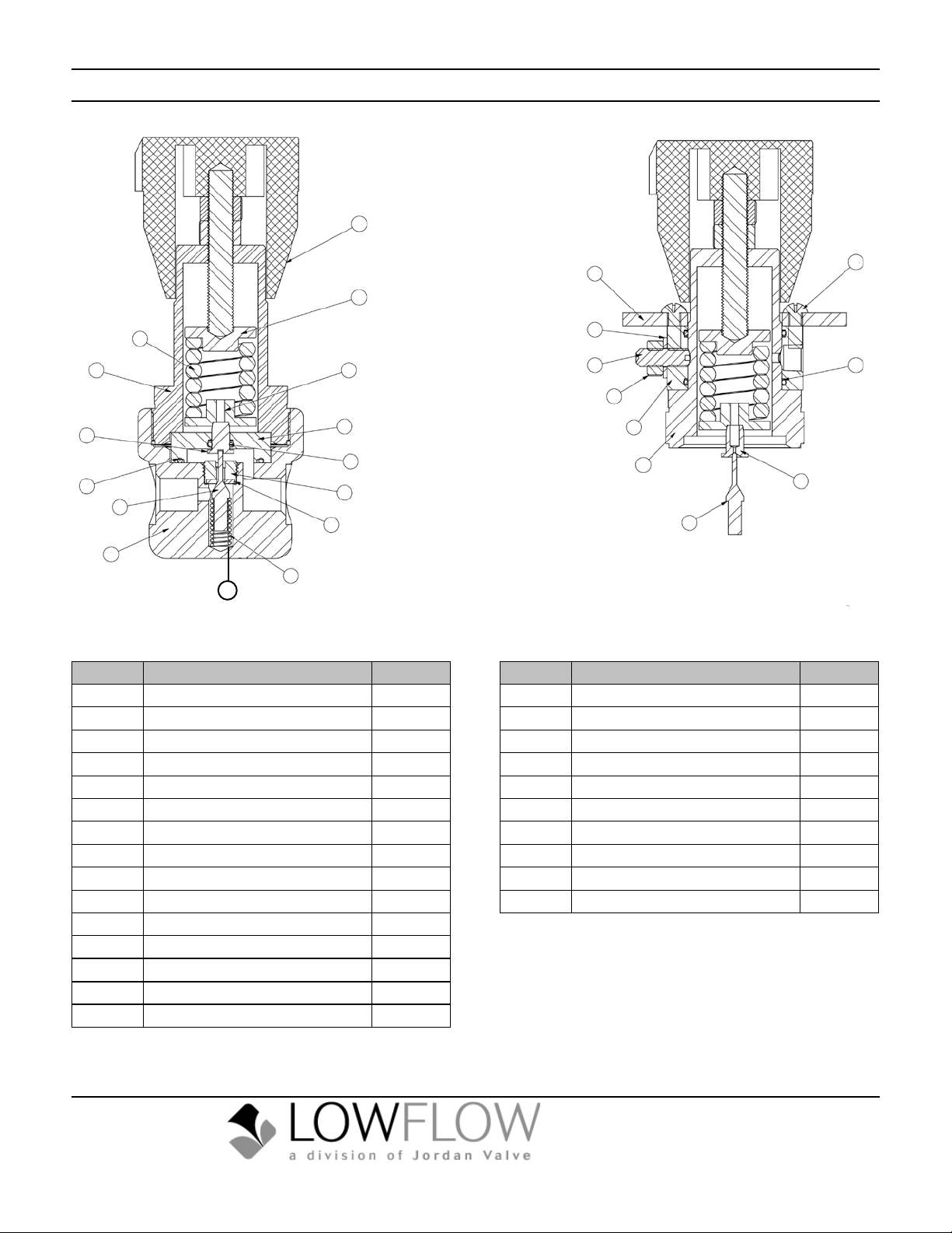
Illustration & Parts List
5
3
4
6
14
10
9
11
12
2
13
7
1
8
15
JRPH Standard JRPH Captured Vent
Item No. Description Quantity
1 Body 1
2 Seat Holder 1
3 Spring Seat 1
4 Range Spring 1
5 Knob Assembly 1
6 Spring Housing 1
7 Seat 1
8 Return Spring 1
9 Cylinder 1
10 Spring Seat 1
11 O-Ring #10 1
12 O-Ring #23 1
13 Plug 1
14 Piston 1
15 Spring Guide 1
23
24
19
20
18
21
16
15
22
17
Item No. Description Quantity
15 Spring Housing 1
16 Cv Collar 1
17 Plug 1
18 O-Ring, #27 2
19 Threadeseal 1
20 SHSS-Cup PT, 1/4-20 x 3/4” 1
21 Hex Nut 1/4-20 1
22 Piston 1
23 Mounting Flange 1
24 SHCS 6-32 x 1/2” 4
Bulletin IM-JRPH-0214
3170 Wasson Road • Cincinnati, OH 45209 USA
Phone 513-533-5600 • Fax 513-871-0105
lowfl[email protected] • www.lowflowvalve.com
 Loading...