

Lowell MP16 User Manual
Model No.
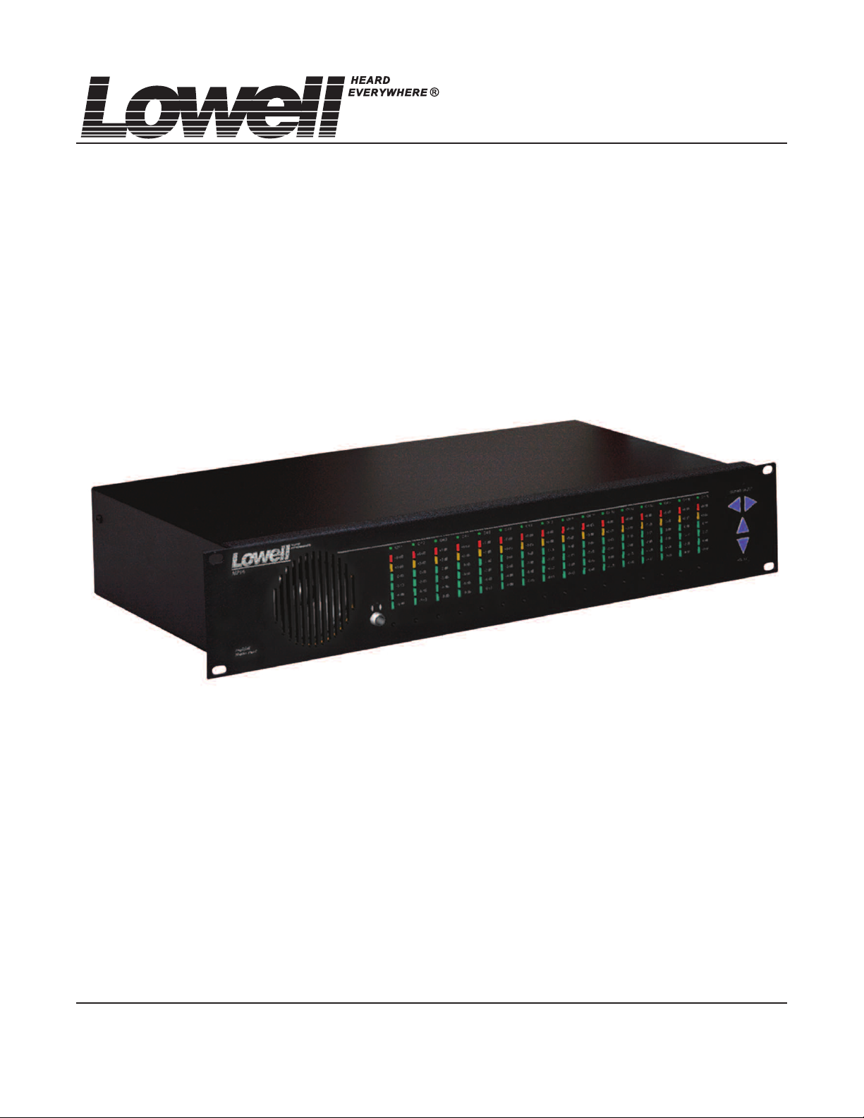
MP16
Amplified Monitor Panel
User Manual
Sixteen channels of visual monitoring
and 16 x 1 selectable aural monitoring
through choice of line or speaker
levels per channel.
© Lowell Manufacturing Company, 100 Integram Dr., Pacific, Missouri 63069 U.S.A., ph. 800.325.9660 www.lowellmfg.com
Lowell makes every effort to provide accurate information and reserves the right to change specifications and/or improve manufacturing methods without notice. 11.03.11
Immediately upon receipt of equipment, carefully inspect the shipping container and contents for damage. Immediately report any damage
o the freight company and dealer/Lowell. Carton contents: MP16 amplified monitor, power supply module (with attached cord and connector),
t
user manual
I. DESCRIPTION: The MP16 amplified monitor is a 16 channel audio level display panel and a selectable (1 of 16 channels)
audio monitor. Ten levels of audio are displayed on a vertical array of colored LEDs (4 green, 1 yellow, 1
ed). Each channel has a 3-position level selection switch (0.077, 0.775, and 70.7 volts) on the rear panel.
r
These are the levels that are nominally displayed at the 0dB LED (factory settings). Level settings for each
channel are user-adjustable over a wide range at an individual trimmer on the front panel. The MP16 is
housed in a 2RU chassis.
Front Panel Features:
• Loudspeaker
• On/off switch with green LED indicator
• 16 level-indicating LED arrays (multi-colored)
• Buttons to select channel monitored
• Buttons to raise/lower volume
• Headphone jack for audio monitoring with/without the
speaker on
• 16 channel-indicating LEDs (green)
• Pocket to hold label for channel identification (1/2” high)
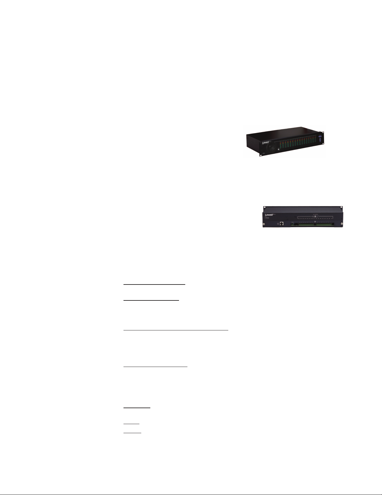
Rear Panel Features:
• 5-pin DIN connector to plug in power supply
• 2-pin, 2-piece terminal block for the balanced line level
(600 ohms) audio monitor output
• Two (16-pin) 2-piece terminal blocks to input audio (balanced or unbalanced). The right terminal block is for channels 1 through 8; left terminal block is for channels 9 through 16.
• 16 switches to set levels (each switch has 3-positions).
• Bottom half of panel can be removed to access terminal blocks and level-setting switches.
II. SPECIFICATIONS: Connections:
• Headphone Connector (J3)
sleeve is common, tip and ring are audio out.
• Power Connector (J908):
Din, 5 pin, 180 degrees
Pins 1 and 3: 18 volts AC, 2 amperes, 50-60 Hz in
Pin 2 is chassis ground
• Audio Line Balanced 600 ohm Output (TB901): Level-adjustable by internal pot, RV901, LINE OUT
TRIM (factory setting is 0dBu when rear panel switch is in center position, front panel pot is at factory
setting, and 0dBu is introduced into selected channel input on rear panel. The signal follows the front
panel channel selector. The connector is a 2-pin terminal block. It accepts wire sizes from 30AWG to
12AWG
• Input Connectors (TB1 TB2)
(header) is a Phoenix MSTBA 2.5/16-G. These plugs accept wire sizes from 30AWG to 12AWG. Both
parts are colored green. If the pairs are shielded, there is no shield termination provision at this end.
The other end should have the shield(s) terminated.
Mechanical:
• Dimensions: Rack-mount panel is 2RU (3.5 inches) high; front panel is 19 inches wide. The chassis
is 17.25 inches wide, 9 inches deep, and 3.25 inches high.
• Weight
• Exterior: Black chassis. Black speaker switch. Blue buttons.
: 6.5 lbs. / 2.951 kg. (unit); 1.5 lbs. / 0.681 kg (power supply)
: 1/4-inch stereo jack can also be used with monaural headphones. The
: There are 16 two-conductor plugs. The part that is on the circuit board
1

Electrical:
• Power requirements: 18 volts AC, 50 to 60 Hz 2 amperes or 18 volts DC, 1.25 amperes. Power
adapter module to convert 120 volts AC to 18 volts AC is included.
• Signal Inputs:
Input Impedances:
Input switch at 77 millivolts (0.070 volts), impedance = 40 kilohms
nput switch at 775 millivolts (0.70 volts), impedance = 400 kilohms
I
Input switch at 70.7 volts, impedance = 40 megohms
Input voltages, nominal (factory settings): 77 millivolts, 775 millivolts, 70.7 volts, depending on position of input switch. The headroom is 9dB. (Front panel adjustment can change these numbers.)
• Signal Output
Output Impedance: Balanced, 600 ohms
Output Level: 0dBu (factory setting when input switch is in center position, and 0dBu, 1kHz signal
is input).
• Speaker Amplifier Output:
Power: 10 watts into 3.2 ohms.
• Headphone Jack Output: Caution: Lower the volume BEFORE putting on headphones. Four
volts rms open circuit, maximum, 100 ohms output impedance peroutput (of two outputs). Output
into 32 ohms: 1 volt rms One volt rms at 32 ohms is approximately 30 milliwatts, SPL ~ 109dB)
Depending on level and duration, noise, sound or music can be a minor irritant, disturbance or
threat to hearing. Federal, state, and local agencies have established standards for how much
noise, sound or music is acceptable. The table below is extracted from U.S. Department of Labor
noise regulations.
Sound level (dB), A-weighting, SLOW response Duration per day (hours)
III. INSTALLATION: Refer to diagram on next page.
Mechanical: Thel MP16 can be rack-mounted in 2RU panel space. The power supply for the MP16 is a
desktop unit. Mechanically secure the power supply so the plug stays in the wall.
:
90 8
95 4
100 2
105 1
110 1/2
115 1/4
Electrical: Connections to inputs via 2-pin plug-in terminal blocks (plug in rear panel).
Power: The output of the power supply module plugs into the rear panel DIN connector.
Input Signal: Terminal blocks TB1 and TB2 are the inputs. Since the terminal blocks are 2-piece, the plug
part can be pre-wired before it’s plugged into rear panel terminal blocks. The connection for each channel
is a pair of terminals. The shield, if present, should be terminated at its other end, or, if required at the
MP16 end, daisy chain the shields and connect them to chassis/earth. The terminal blocks accept a range
of wire sizes from 30 AWG to 12 AWG.
Setting Levels:
• Access: Remove the lower half of the rear panel by unscrewing 2 thumb screws on either side. Set
the selector switch for each channel for the expected input level. Use the illustration on rear panel as
a guide.
• Output Signal (“LINE OUT”) (Line level, balanced, 600 ohm at TB901):
Wire the two contact terminal block plug and plug it in. The terminal blocks accept a range of wire
sizes from 30 AWG to 12 AWG. A shield can be tied as above or at the other end of the wiring run.
2
 Loading...