

Lowell MA30 User Manual
MA30
INSTALLATION SHEET
AND OPERATORS MANUAL
1
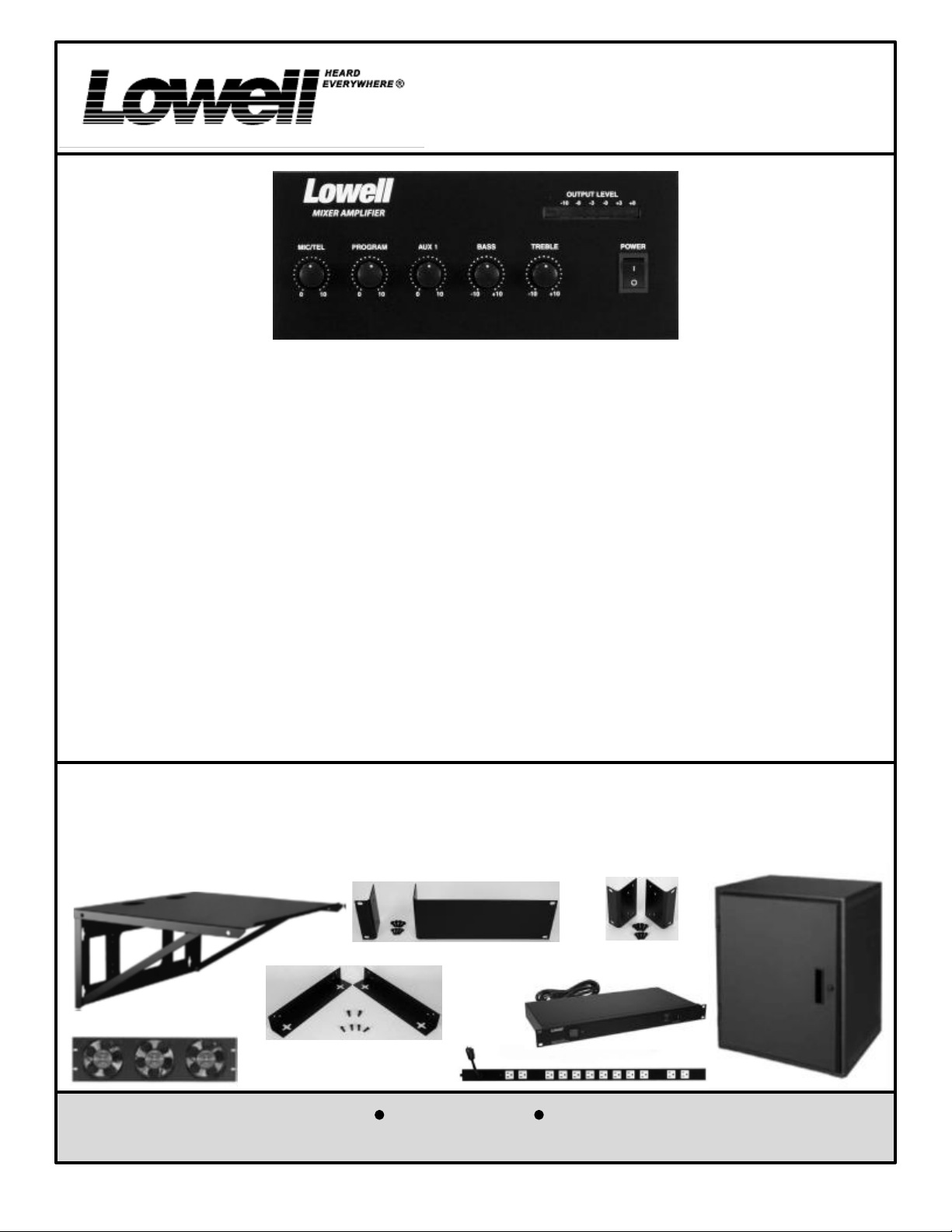
MA30 General Description:
The MA30 is equipped with a 30 watt power amplifier with 4W, 8W, 25V, and 70V speaker outputs available at screw
terminals. The unit is powered by 120VAC 60Hz. The main AC input is protected by a circuit breaker on the rear
panel. An unswitched convenience AC outlet is provided on the rear panel that is protected by a separate circuit
breaker. The mixer/amplifier includes 3 input channels. The first channel (marked MIC/TEL on the front panel) is
switchable for microphone or telephone inputs and also includes a switch to select the AUX 2 dual combining RCA-
phono connectors. This channel also includes a TEL/MIC switch. In the TEL (telephone) position, this switch pads
the input to allow the channel to be fed by a 600W balanced line level telephone page port output signal. The first
channel includes a MUTE ON/OFF switch. When the mute switch is turned ON, a dynamic microphone or
telephone input will mute the AUX 1, Aux 3, or Program inputs. The second channel (marked PROGRAM on the
front panel) is switchable for program input screw terminals or AUX 3 dual combining RCA-phono connectors. The
third channel (marked AUX 1 on the front panel) is for the AUX 1 dual combining RCA-phono connectors. The front
panel also includes BASS and TREBLE controls, a power-on LED, and an output level LED indicator.
Getting Started:
Please study carefully the “IMPORTANT SAFETY INSTRUCTIONS” that are given on page 2 before applying power
to your MA30 mixer/amplifier. Those experienced with the use of a mixer/amplifier will find that the input jacks,
output jacks, and controls follow industry standard conventions and will be very intuitive. Standard 4W, 8W, 25V,
and 70V speaker outputs are provided. Those that are not familiar with the speaker wiring required for these
industry standard outputs will find a very helpful section covering this topic on pages 6, 7, and 8 of this “Installation
Sheet and Owner’s Manual”.
Optional Accessories (sold separately):
Lowell Manufacturing offers the optional 30WK wall kit (used to wall mount the MA30 Mixer/Amplifier), the 30RK
rack kit (used to mount the MA30 Mixer/Amplifier in a 19" rack), the 30HRK half-rack kit (used to mount the MA30
Mixer/Amplifier in a half rack), along with a full line of 19" equipment cabinets, half-rack cabinets, wall mount
shelves, rack mount AC power panels, AC power strips, and cooling fans that can be used to install the Lowell
Amplifier products. See www.lowellmfg.com for product details.
30RK
30WK
30HRK
Lowell Manufacturing Company
Call: 800-325-9660
Fax: 636-257-6606 Click: www.lowellmfg.com
100 Integram Drive Pacific, Missouri 63069 U.S.A.
1
REMOVABLE
PHOENIX
Instruction Sheet
CONNECTOR
IS-MA30
Issued: 9-10-14
IMPORTANT SAFETY INSTRUCTIONS
Read these instructions. Keep these instructions. Heed all warnings.
Follow all instructions. Do not use this apparatus near water.
Clean only with a dry cloth.
Do not block any ventilation openings. Install in accordance with manufacturer’s instructions .
Do not install near any heat sources such as radiators, registers, stoves, or other apparatus (including amplifiers)
that produce heat.
Do not defeat the safety purpose of the polarized or grounding-type plug. A polarized plug has two blades with
one wider than the other. A grounding-type plug has two blades and a third grounding prong. The wide blade or
third prong is provided for your safety. If the provided plug does not fit into your outlet, consult an electrician for
replacement of the obsolete outlet.
Protect the power cord and plug from being walked on or pinched particularly at plugs, convenience receptacles,
and the point where it exits from the apparatus.
Only use attachments and accessories specified by the manufacturer.
Use only with the cart, stand, tripod, bracket, or table specified by the manufacturer, or sold with the apparatus.
When a cart is used, use caution when moving the cart/apparatus combination to avoid injury from tip-over.
Unplug this apparatus during lightning storms or when unused for long periods of time.
Refer all servicing to qualified service personnel. Servicing is required when the apparatus has been damaged in
any way, such as power supply cord or plug is damaged, liquid has been spilled or objects have fallen into the
apparatus, the apparatus has been exposed to rain or moisture, does not operate normally, or has been dropped.
The plug on the power cord is the AC mains disconnect device and must remain readily operable. To completely
disconnect this apparatus from the AC mains, disconnect the power supply cord plug from the AC receptacle.
This apparatus shall be connected to a mains socket outlet with a protective earthing connection.
When permanently connected, an all-pole mains switch with a contact separation of at least 3 mm in each pole
shall be incorporated in the electrical installation of the building.
If rack mounting, provide adequate ventilation. Equipment may be located above or below this apparatus, but
some equipment (like large power amplifiers) may cause an unacceptable amount of hum or may generate too
much heat and degrade the performance of this apparatus.
This apparatus may be installed in an industry standard equipment rack. Use screws through all mounting holes
to provide the best support.
WARNING: To reduce the risk of fire or electric shock, do not expose this apparatus to rain or moisture. Apparatus
shall not be exposed to dripping or splashing and no objects filled with liquids, such as vases, shall be placed on the
apparatus. This product may contain chemicals known to the State of California to cause cancer, or birth defects or
other reproductive harm.
NOTE: This equipment may generate, uses, and can radiate radio frequency energy and, if not installed and used in accordance
with the instructions, may cause harmful interference to radio communications. However, there is no guarantee that interference
will not occur in a particular installation. If this equipment does cause harmful interference to radio or television reception, which
can be determined by turning the equipment off and on, the user is encouraged to try to correct the interference by one or more
of the following measures: Reorient or relocate the receiving antenna.
Increase the separation between the equipment and receiver.
Connect the equipment into an outlet on a circuit different from that to which the receiver is connected.
Consult the dealer or an experienced radio/TV technician for help.
CAUTION: Changes or modifications not expressly approved by Lowell Manufacturing will void the manufacturers warranty.
Lowell Manufacturing Company
Call: 800-325-9660
Fax: 636-257-6606 Click: www.lowellmfg.com
100 Integram Drive Pacific, Missouri 63069 U.S.A.
2
REMOVABLE
PHOENIX
CONNECTOR
Instruction Sheet
IS-MA30
Issued: 9-10-14
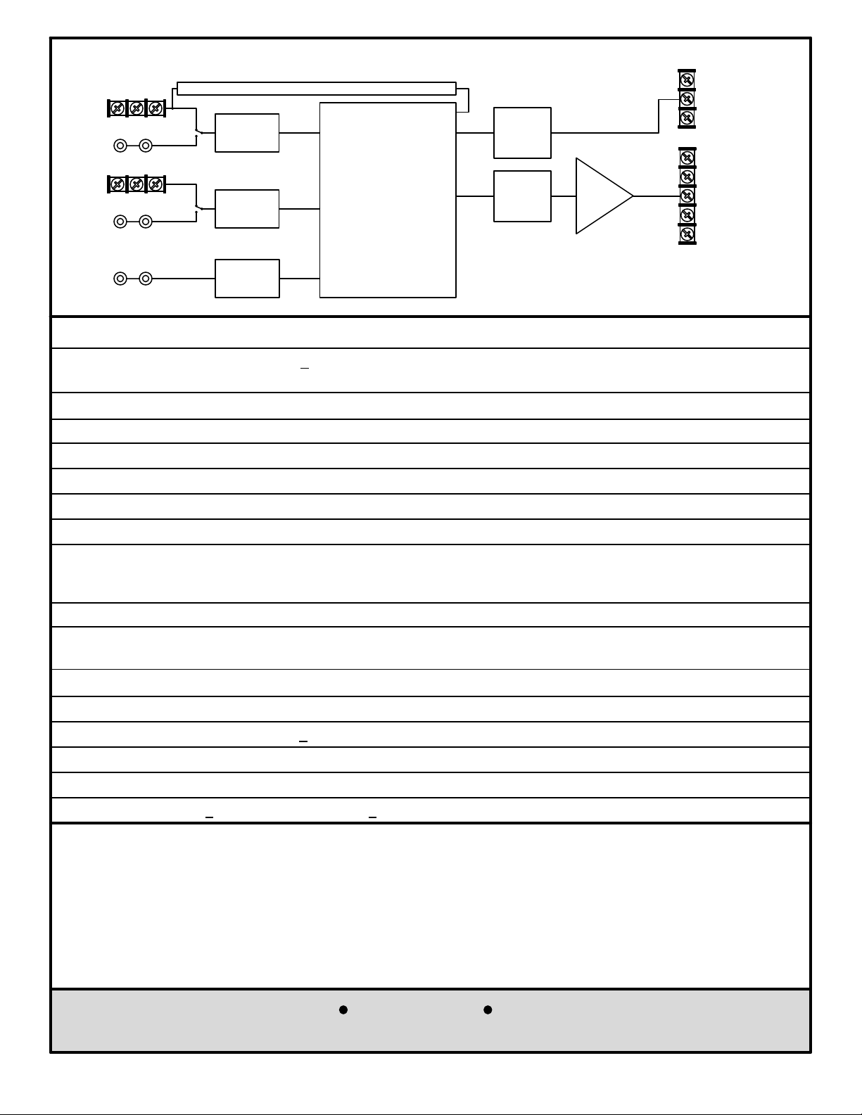
MIC / TEL
Input
AUX 2
Input
PROGRAM
Input
AUX 3
Input
G COM HOT
G COM HOT
Amplifier Block Diagram
Switch Defeatable Circuit Mutes AUX1, AUX3, and PROGRAM Inputs
Note: The MOH output is only
MIC /TEL
Volume
Control
PROGRAM
Volume
Control
fed by the AUX 1, AUX 2, and
AUX 3 input signals. The MIC/
TEL and PROGRAM inputs are
NOT fed to the MOH output. No
front panel controls affect the
MOH output.
Mixing
And
Control
Section
MOH
Level
Control
Bass and
Treble
Controls
Power
Amplifier
30W RMS
8W
MUSIC-ON-HOLD
COM
(MOH)
OUTPUT
G
70V
25V
SPEAKER
LEVEL
8W
OUTPUTS
4W
COM
AUX 1
Input
AUX 1
Volume
Control
Technical Specifications
AC Supply Voltage: 120VAC 60Hz + 10%,
Power Consumption: 90W @ Rated Power
Convenience AC Outlet: 500W maximum unswitched outlet
Dimensions: 8.35" wide x 3.46" high x 10.83"deep (212mm wide x 88mm high x 275mm deep)
Weight: MA30: 8.82LBS. (4KGS)
Shipping Weight: MA30: 10.0LBS. (4.54KGS)
Color: Black
Accessories: 30WK (wall mounting kit), 30RK (rack kit), and 30HRK (half-rack kit) are sold separately.
Speaker Level Outputs: Screw terminal strips,
Main Output: 4W, 8W, 25V, 70V, 30W RMS
Music-On-Hold: (MOH), 1W @ 8W
Mic Input: Screw terminals, 1mV @ 600W balanced (Phantom power is not available.)
Telephone Input: Screw terminals (switchable, same terminals as mic input)
100mV @ 10kW balanced
Program Input: Screw terminals 100mV @ 10kW balanced
Aux Inputs 1-3: Dual parallel unbalanced RCA-phono jacks, Stereo converted to mono, 150mV @ 10kW
Frequency Response: 50Hz-20KHz + 3dB (Test signal inserted at aux input)
Total Harmonic Distortion: Less than 1% at 1kHz at rated power.
Signal to Noise Ratio: 80dB (Test signal inserted at Aux input)
Tone Controls: Bass + 10dB @ 100Hz, Treble +10dB @ 10kHz,
Amplifier Muting-Priority Scheme
The amplifier includes unique voice-activated (VOX) ducking/muting circuitry. The mute circuit is only active when
the “MUTE” switch on the rear panel has been turned “ON”. When a page is made into the microphone or
telephone input (Channel MIC/TEL), the PROGRAM, Aux 1, and Aux 3 music inputs will duck in volume (not be
completely muted). If the incoming page is strong enough in level, the music volume will be completely muted.
When the page has been completed, the volume of the music will return to its normal level. Note that AUX 2 is not
involved in the muting circuit, because when the Mic/Tel–Aux 2 switch is in the Aux 2 position, the Aux 2 input is
active but the MIC/TEL input is defeated so muting by the MIC/TEL input is not an issue.
Lowell Manufacturing Company
Call: 800-325-9660
Fax: 636-257-6606 Click: www.lowellmfg.com
100 Integram Drive Pacific, Missouri 63069 U.S.A.
3
Instruction Sheet
IS-MA30
Issued: 9-10-14
 Loading...