

Lowell LWR-723 Specifications
Spec No. 1620 [REV. 08.02.17] Page 1/2
Model No.
UL 2416
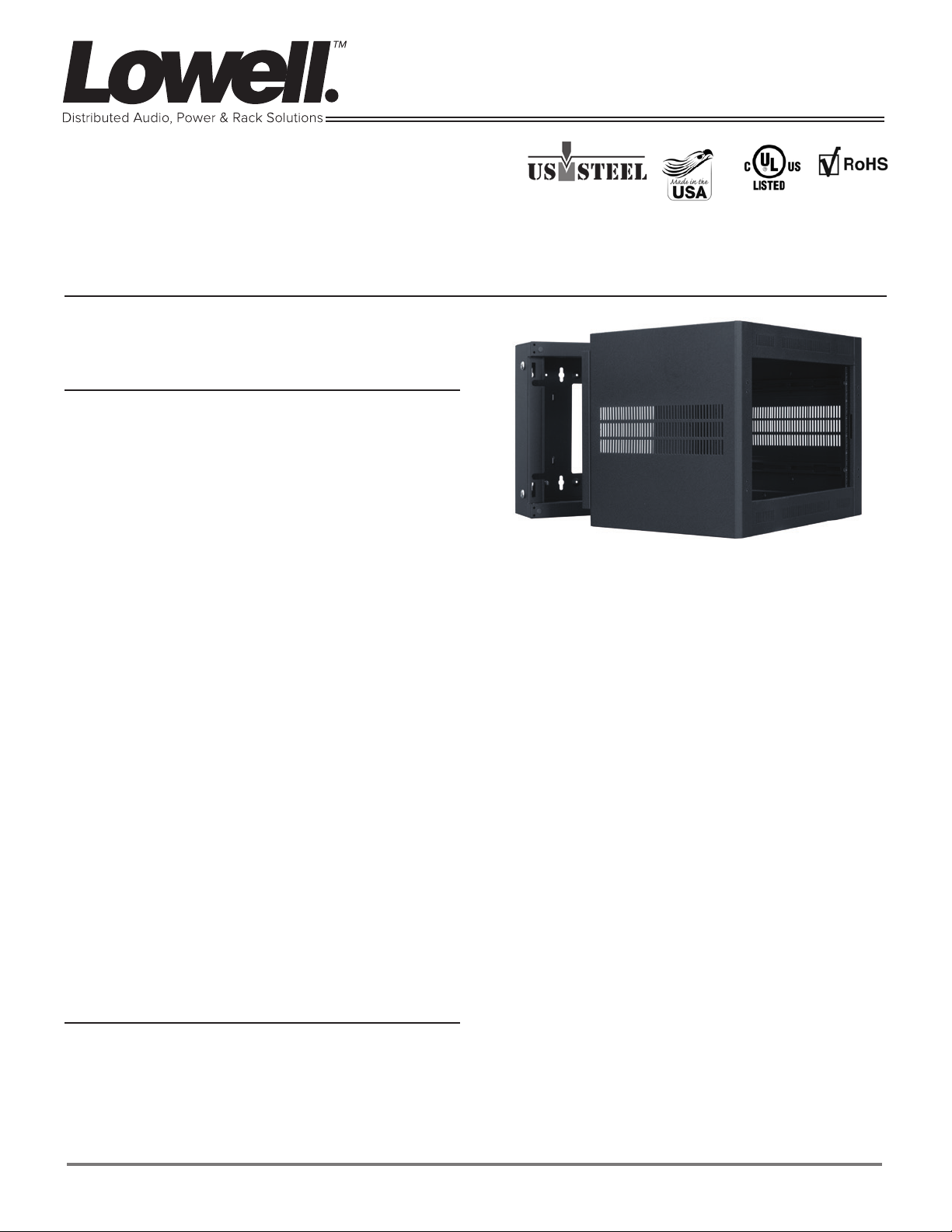
LWR-723
Sectional wall-mount rack
7U x 23.05”D x 23.06”W
Construction & Features
• 16-gauge welded steel backbox and separate mounting
section are shipped in two boxes so the backbox can be
field-installed while the mounting section is loaded with
equipment at the shop.
• Overall measurements: 18.375”H x 23.05”D x 23.06”W.
Useable depth: 20”, allowing partial extension of equipment
into backbox.
• Load capacity 125 lbs.
• Backbox: 5.80”D with keyhole mounting slots on 16” centers, 10” x 10” opening to mount over electrical pull boxes,
1/4-20 ground stud, embossed dimples on back plane for installation of board-mounted accessories, removable knockout panels on top/bottom, and 2 keyed side locks (keyed
differently than optional front door)
• Front Mounting Section: 17.06”D with fully gusseted corners
and triple formed (side-to-bottom/side-to-top) wrap design
mounts to backbox from the inside with 2 heavy duty springloaded L-pins (self seating, positive locking). Pins can be
moved to change swing orientation. Strength equivalent to
3/16” thick steel. Welded sides have vents and notches to
accommodate optional single fan kit. Beveled front corners.
Front vents (top and bottom of frame). Four knockouts for
wireless antennas on rack top and bottom. One pair adjustable mounting rails, tapped 10-32 (recessed 0.625”).
Integral top/bottom rails on E.I.A. NOTE: Minimum clear-
ance to allow the mounting section to swing open 90
degrees is 17.26 inches, plus an additional inch for the
optional front door. The mounting section can actually
swing open greater than 90 degrees if additional room
is provided. Roller closure keeps mounting section closed
without mandatory locking.
• E.I.A. compliant, UL 2416 Listed
• Made in U.S.A. with 100% certified U.S. steel.
• Pilot Point screws (captive washers)
A&E Specifications
The E.I.A. compliant, UL2416 listed, welded sectional wall
rack shall be Lowell Model No. LWR-723, which shall consist
of a backbox and mounting section made in the U.S.A. from
16 gauge certified U.S. steel. Overall measurements shall
be 18.375”H x 23.05”D x 23.06”W (7U racking space). The
mounting section shall be 17.06”D with triple formed side-tobottom, side-to-top wrapped construction to achieve strength
equivalent to 3/16” thick steel. It shall include side vents, one
Lowell makes every effort to provide accurate information while reserving the right to change specifications and/or improve manufacturing methods without notification.
©2017 Lowell Manufacturing Company, 100 Integram Dr., Pacific MO 63069 | tel. 800.325.9660 | www.lowellmfg.com
pair adjustable mounting rails tapped 10-32 (with mounting
hardware), four knockouts for antennas (top and bottom), and
integral rails on E.I.A. spacing (top and bottom). The mounting section shall attach to the backbox on the inside with two
heavy duty, spring-loaded L-pins (self seating, positive locking), which can be attached on either side to alter swing orientation. The backbox shall be 5.80”D with keyhole mounting
slots on 16” centers, 10” x 10” rear opening, embossed dimples and lacing points on the back plane, knockout panels with
combination knockouts (.75-.5”, 1.5-1”) on top and bottom,
and two keyed side locks. The rack shall have a black wrinkle
powder epoxy finish.
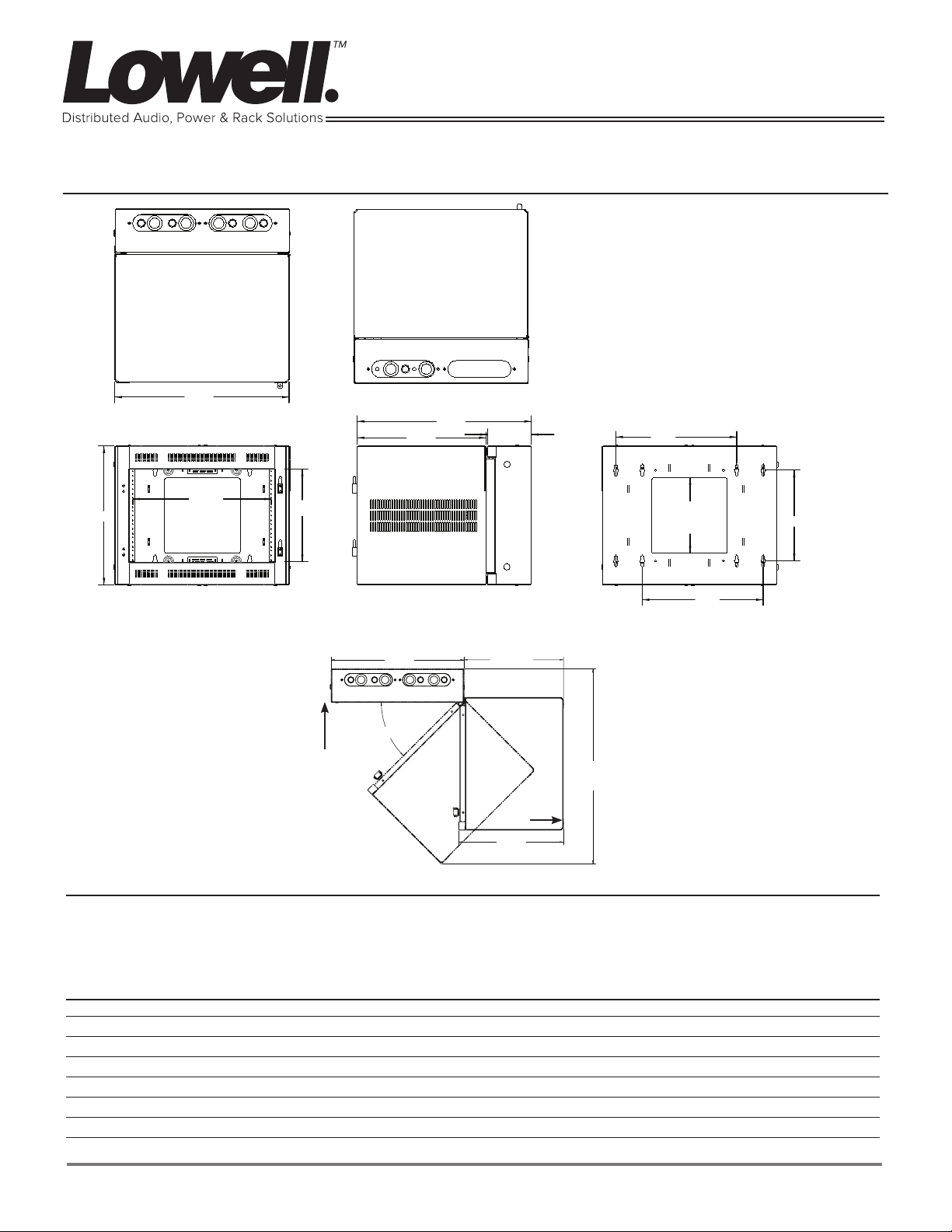
Technical Drawings
Spec No. 1620 [REV. 08.02.17] Page 2/2
Measurements are inches.
RACK TOP features 4 knockouts for wireless
antennas (.5”), 2 knockout panels with combination knockouts (.75-.5”, 1.5-1.”)
RACK BOTTOM features 4 knockouts for wireless antennas (.5”), 1 blank panel, 1 panel with
combination knockouts (.75-.5”, 1.5-1.”)
23.063
TOP VIEW
18.312
C
C
to
L
18.375
L
12.250
FRONT VIEW
locks
CORNER INSTALL DETAIL:
• Allow sufficient clearance for access to side locks (5”)
• Allow additional 1” for optional door depth
• Minimum clearance for 90 degrees open is 17.26”
23.06”
45.00Ā
BOTTOM VIEW
17.056
23.051
5.807
17.26”
clearance
18.18”
33.87”
Optional door
16.00
10.000
X 10.00
OPENING
12.00
16.00
Options (order separately)
• Front Door (surface-mount): Solid steel, fully-vented steel, or smoked plexiglass mounts left or right. (LFD Series)
• Mounting Rails: sold in pairs (RRD-7)
• Single Fan Kit: Single whisper fan is ideal for spot cooling (FW1-KIT)
Model No. Summary
Model No. Description Racking Space Usable Depth Overall Depth Overall Height Overall Width
LWR-723 Sectional wall rack 12.25” / 311mm / 7U 20” / 508mm 23.05” / 585mm 18.375” / 467mm 23.06” / 586mm
LFD-7 Solid steel front door
LFD-7FV Fully vented front door
LFD-7P Smoked plexiglass front door
RRD-7 Mounting rails (7U, 1pr)
FW1-KIT Single fan kit
One rack unit (RU or U) = 1.75” or 44.45mm
Lowell makes every effort to provide accurate information while reserving the right to change specifications and/or improve manufacturing methods without notification.
©2017 Lowell Manufacturing Company, 100 Integram Dr., Pacific MO 63069 | tel. 800.325.9660 | www.lowellmfg.com
 Loading...