

Lowell LWR-1019 Specifications
Model: LWR-series
Lowell Wall-mount Rack – 19"D
escription:
D
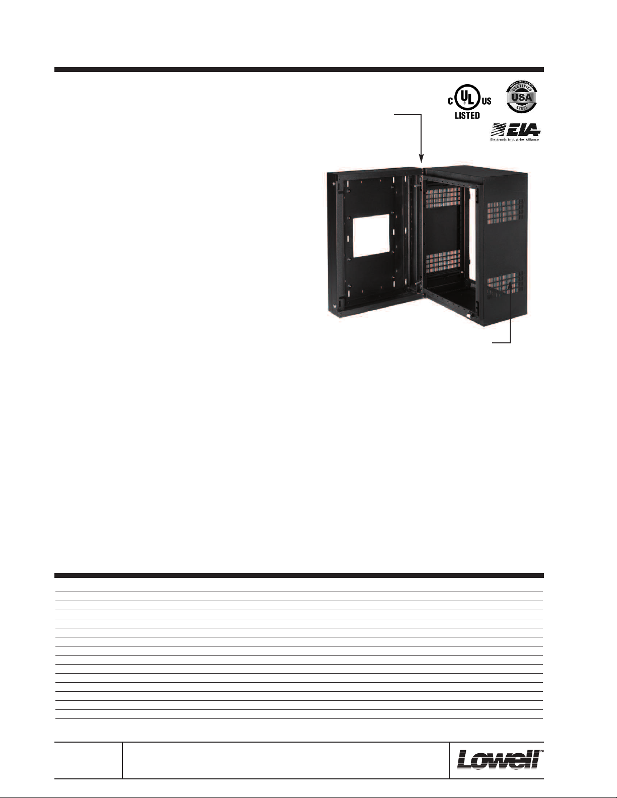
The E.I.A. compliant, UL Listed (Standard 1678) sectional wall-mount
rack consists of a sturdy steel backbox and mounting section that are
boxed separately for convenience (the backbox can be field-installed
while the mounting section is loaded with equipment at the shop). The
mounting section provides greater than 90˚ open-swing access for
servicing and requires a minimum clearance of 14.18" (plus 1" if optional front door is used). The mounting section mounts to the backbox
from the inside using two heavy duty spring-loaded L-pins that are selfseating and positive-locking upon closure, providing fast, secure installation without visible hinging or hardware.
Features:
• Mounting Section: The stability of the L-pin design, combined with
the section’s fully gusseted corners and triple formed side-tobottom and side-to-top wrapped design, achieve strength equivalent to 3/16" thick steel for dependable load-bearing support. A
roller-closure device allows the mounting section to seat in a closed
position without mandatory locking. Includes one-pair of (10-32)
adjustable rails that are recessed .625" to allow 1.375" space between equipment knobs and (optional) front door. Also includes integral rails on E.I.A. spacing at top and bottom for mounting and
lacing. Vented sides have holes to accommodate mounting an
optional fan kit (FW1-KIT).
• Backbox: 4.69”D with 16" mounting centers and removable knockout panels at top and bottom. Features 10" x 10" opening to mount
over electrical pull boxes and embossed dimples on back plane
for installation of board-mounted accessories. Includes two side
key-locks that are keyed differently than (optional) front door.
• Heavy-duty load capacity (see model listings)
TM
• PilotPoint
RSP-series for extra hardware).
• 16-gauge steel with black wrinkle powder epoxy finish.
• Made in U.S.A. with 100% certified U.S. steel
Options: (order separately)
• Front Door: solid steel, fully-vented steel, or steel frame with
smoked Plexiglas insert (see LFD-series).
• Rack Rails: extra mounting rails can be ordered to support rear of
rack-mounted equipment (see RRD-series).
A&E Specifications:
The E.I.A. Compliant, UL Listed (Standard 1678) welded rack shall be
Lowell Model ___________. The rack shall consist of two parts, a backbox and a mounting section with side vents. The unit shall have overall
screws with 5.1 hardness and captive washers (order
Mounting section secures
to backbox with internal
L-pins.
Removable knockout
panels top and bottom.
Side key-locks.
Vented sides include notches to
mount optional fan kit (FW1-KIT).
measurements of ________"H x 23.06"W x 19.05"D. The mounting
section shall be 14.18"D and formed of 16-gauge certified U.S. steel
with triple-formed side-to-bottom and side-to-top wrapped construction
to achieve strength equivalent to 3/16" thick steel. It shall include one
pair of front-to-rear adjustable mounting rails tapped 10-32 (mounting
hardware included), integral rails on E.I.A. spacing (top and bottom),
and knockouts for BNC style antennae (top and bottom). The mounting
section shall attach to the backbox from the inside using two heavyduty, spring-loaded L-pins that are self seating and positive locking.
The L-pins shall be capable of being moved to the opposite side to
change swing orientation if needed. The backbox shall be 4.69"D and
formed from 16-gauge certified U.S. steel with keyhole mounting slots
on 16" centers. It shall include a 10" x 10" opening for mounting over
electrical pull boxes, removable knockout panels (top and bottom), embossed dimples and lacing points on the back plane, and two locks on
the 4.69"D side for security between the backbox and the mounting
section. Knockout panels shall be equipped with 0.5" knockouts for
BNC and compound knockouts for conduit size .75"-.5" and 1.5"-1".
The mounting section and backbox shall have a black wrinkle powder
epoxy finish.
Model No. Description Rack Units* Panel Space Mtg Section D Backbox D Usable D**
LWR-719 Wall-Mount Rack (sectional) 7 12.38" 14.18" 4.69" 16.00" 18.38" 23.06" 19.05" 125 lbs.
LWR-1019 Wall-Mount Rack (sectional) 10 17.63" 14.18" 4.69" 16.00" 23.63" 23.06" 19.05" 150 lbs.
LWR-1219 Wall-Mount Rack (sectional) 12 21.13" 14.18" 4.69" 16.00" 27.13" 23.06" 19.05" 150 lbs.
LWR-1619 Wall-Mount Rack (sectional) 16 28.13" 14.18" 4.69" 16.00" 34.13" 23.06" 19.05" 200 lbs.
LWR-2119 Wall-Mount Rack (sectional) 21 36.88" 14.18" 4.69" 16.00" 42.88" 23.06" 19.05" 250 lbs.
LWR-2419 Wall-Mount Rack (sectional) 24 42.13" 14.18" 4.69" 16.00" 48.13" 23.06" 19.05" 300 lbs.
LWR-3519 Wall-Mount Rack (sectional) 35 61.38" 14.18" 4.69" 16.00" 67.38" 23.06" 19.05" 300 lbs.
RRD-7 Rack Rails (1-pr) 7
RRD-10 Rack Rails (1-pr) 10
RRD-12 Rack Rails (1-pr) 12
RRD-16 Rack Rails (1-pr) 16
RRD-21 Rack Rails (1-pr) 21
RRD-24 Rack Rails (1-pr) 24
RRD-35 Rack Rails (1-pr) 35
* One rack unit (RU or U) = 1.75”
** Usable depth is 16” allowing partial extension of equipment into backbox.
Spec. No. 1039
(rev. 10.10.11)
pg. 1 of 2
©2011 Lowell Manufacturing Company, 100 Integram Dr., Pacific MO 63069. Phone–800.325.9660
Fax—636.257.6606. Lowell makes every effort to provide accurate information while reserving the right to
change specifications and/or improve manufacturing methods without notification. (lowellmfg.com)
Overall H
Overall W
Overall D
Load Capacity
Model: LWR-series
Lowell Wall-mount Rack – 19"D
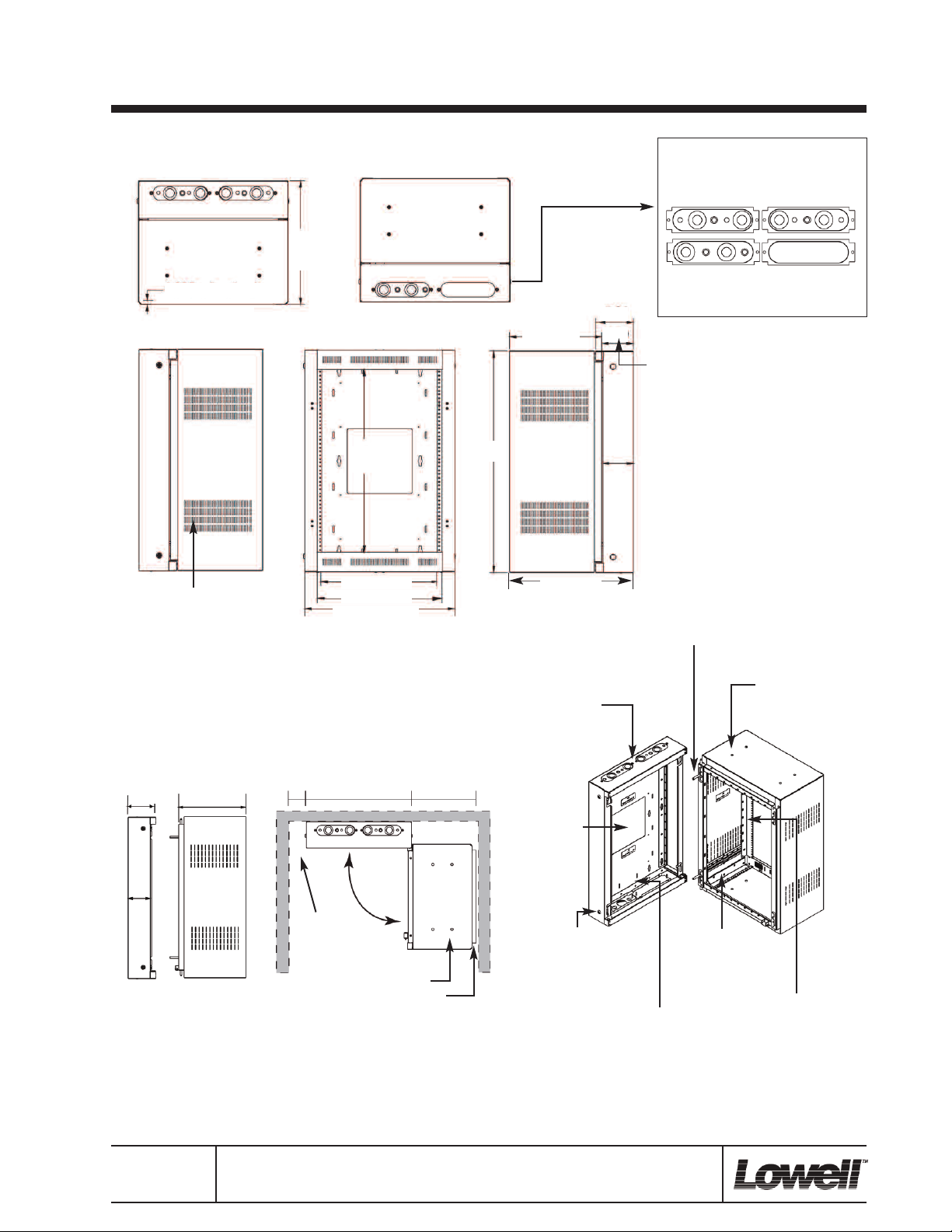
Mounting Section with Backbox.
Top View
9.05
1
verall
o
depth
0.625 rail set-back
23.06 overall width
Side View
Vented sides have
notches to mount
optional fan kit
(FW1-KIT).
Bottom View
Front View
anel
P
Space
17.81 clearance
19.19 panel width
23.06 overall width
Overall
eight
h
Side View
Mtg Section
epth
d
Overall depth
5.81
4.69
KNOCKOUT PANELS:
Top panels have .5" knockouts for wireless
antennae and .75"-.5" and 1.5"-1" knockouts for conduit.
On the bottom, one panel has .75"-.5"
and 1.5"-1" knockouts for conduit; the
other is a blank project panel.
ackbox
B
depth
Mounting section secures to backbox
with spring-loadedl L-pins that can be
moved to change swing orientation.
SIDE DETAIL.
5.81
4.69
14.18
CORNER INSTALL DETAIL.
23.065 15.18
Allow room
to access
side locks.
Allow 14.18" for section depth,
plus 1.0" for (optional) door depth.
Removable
knockout panels
top and bottom.
10 x 10
opening
Side
key-locks.
Embossed dimples and lacing points
on back plane allow flush installation
of board-mounted accessories.
.5" knockouts for
BNC wireless
antennae, top
and bottom.
Integral top
and bottom
rails for mounting or lacing.
Adjustable front
mounting rails.
All measurements are inches.
Spec. No. 1039
(rev. 10.10.11)
pg. 2 of 2
©2011 Lowell Manufacturing Company, 100 Integram Dr., Pacific MO 63069. Phone–800.325.9660
Fax—636.257.6606. Lowell makes every effort to provide accurate information while reserving the right to
change specifications and/or improve manufacturing methods without notification. (lowellmfg.com)
 Loading...