


Lowell ES4T User Manual
INSTRUCTION SHEET #IS-ES4T-ES62T
Recessed Ceiling Speaker Systems
ES-4T SPECIFICATIONS
Driver Type: 4" Dual Cone (with whizzer HF) Driver Type: 6-1/2" Coaxial
Power Rating: 25 watts (EIA Standard 426B) Power Rating: 50 watts (EIA Standard 426B)
Frequency Response: 126Hz – 20kHz + 6dB
Sensitivity: 85.7dB SPL (8W, 1W@1M) Sensitivity: 88.6 dB SPL (8W, 1W@1M)
Dispersion: 135o conical (-6dB @ 2kHz octave) Dispersion: 120o conical (-6dB @ 2kHz octave)
Available Transformer Taps: 100V (16W, 8W, 4W, 2W
taps), 70V (16W, 8W, 4W, 2W, 1W taps), 25V (2W, 1W,
.5W, .25W, .13W taps)
1
Mounting Note: The speaker system must be mounted in accordance with local, state,
Frequency Response: 64Hz – 20kHz + 6dB
Available Transformer Taps: 100V (32W, 16W, 8W,
4.2W taps), 70V (32W, 16W, 8W, 4W, 2W taps), 25V
(4.4W, 2.2W, 1.1W, .55W, .28W taps)
ES-62T SPECIFICATIONS
and federal codes and regulations, and industry standard practices. The 4" speaker
model and accessories are shown in all pictures, but the pictures and instructions are
also applicable to the 6-½” speaker model and accessories.
Lay-in Tile Ceiling
1
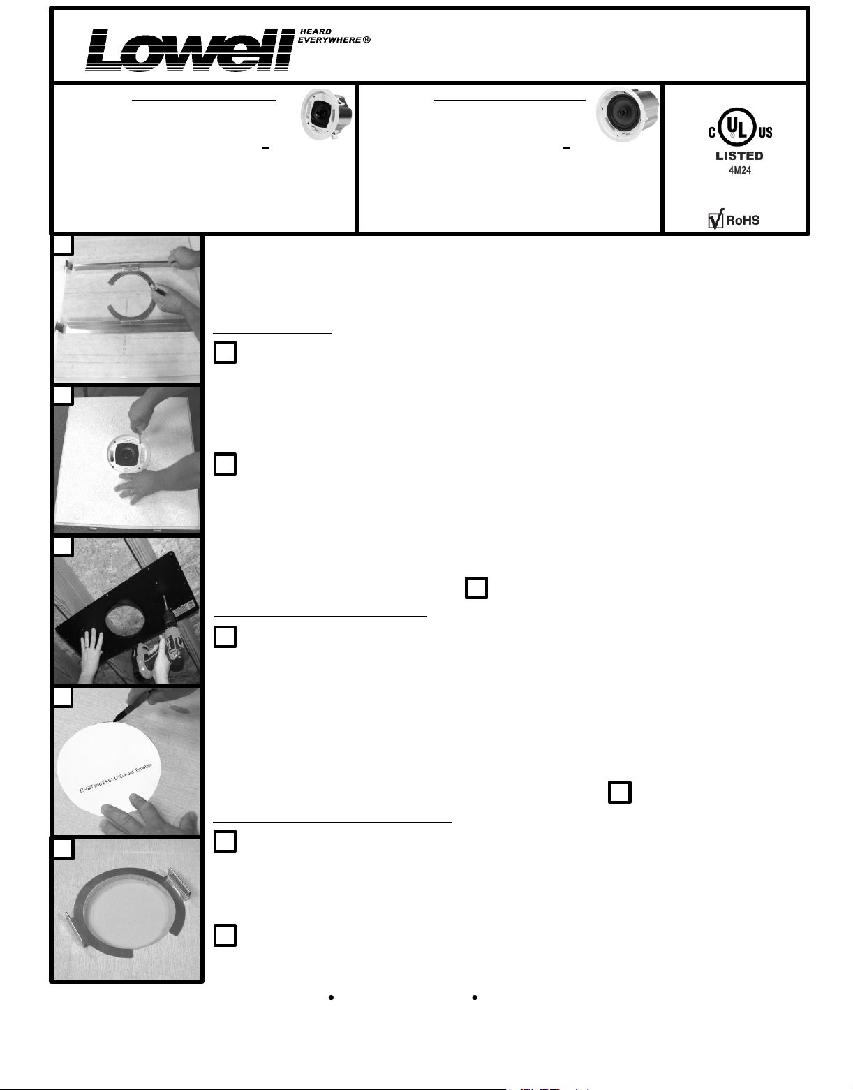
Remove the 2' X 2' or 2' X 4' ceiling tile. Place the tile face down on a soft surface (to
avoid damaging the surface of the ceiling tile). Assemble the C-ring and rails assembly by
2
using 1 screw to attach each rail to the C-ring in the desired location. Place the assembly on
the rear of the tile so that it spans the 2' width of the tile. Trace the inside edge of the C-ring as
shown. The C-ring/rail assembly can be rotated 180 degrees to complete tracing the circle
where the ring has a gap. Use a hole saw to cut out the hole in the ceiling tile.
2
Insert the rear of the speaker through the hole in the tile. Tighten the mounting ears with a
Phillips screw driver so that the ears rotate away from the speaker body and trap the tile
between the speaker and C-ring/rails assembly. Do not over-tighten the mounting ear
screws or the plastic ears can break. As shipped from the factory, the mounting ears can
3
span a ceiling thickness of 1.25". The ears can be removed, rotated 180 degrees, and placed
back on the tightening screws and they will then be capable of attaching to a ceiling thickness
of up to 2.125". Most contractors prefer to wire the speaker before placing the tile/speaker
assembly on the ceiling tile grid. Skip to for speaker wiring.
6
New Drywall (Sheetrock) Ceiling
GENERAL SIGNALING
EQUIPMENT
UL1480 5th EDITION GENERAL SIGNALING
CSA C22.2 NO. 205-M1983, UL2043
SUITABLE FOR USE IN PLENUM SPACES
3
On a new construction project, it is best to install a rough-in bridge before the drywall
ceiling is installed. The ES-4-RIB rough-in bridge (sold separately for use with the ES-4T) and
the ES-6-RIB rough-in bridge (sold separately for use with the ES-62T) are available for this
4
purpose. Holes are provided on the bridge on twenty-four (24) inch centers and sixteen (16)
inch centers for mounting to the bottom of the joists, rafters, trusses, metal rails or other ceiling
support structure. Screw types required to mount the bridge vary widely depending on the
construction of the ceiling structure so mounting screws are not included and will be
supplied by the installer. Mount the bridge with the lip facing downward toward the floor.
When the ceiling contractor installs the drywall, the lip will be used as a router guide to cut the
hole in the ceiling that is required to install the speaker. Skip to for speaker wiring.
Existing Drywall (Sheetrock) Ceiling
4
5
When installing the ES-4T or ES-62T in an existing drywall ceiling, it is important before
cutting the hole, to confirm that there are no obstructions above the drywall ceiling that would
prevent the speaker from being installed at your chosen location. Once the location has been
chosen and it has been determined that no obstructions exist, use the cardboard template
provided to trace the cut-out circle on the ceiling.
5
Use a saw to cut the hole. For a drywall ceiling, the support rails provided need not be
used, but it is recommended that the “C ring” be used to support the cut-out edge of the drywall.
Shown from above the drywall ceiling.
The gap in the C-ring allows the ring to be maneuvered into position as shown.
Lowell Manufacturing Company
Phone: 800-325-9660
Fax: 636-257-6606 (www.lowellmfg.com)
100 Integram Drive
6
Pacific, Missouri 63069 U.S.A.
Printed on 11-18-13
Instruction Sheet:
IS-ES4T-ES62T
Page 1 of 2
6
6
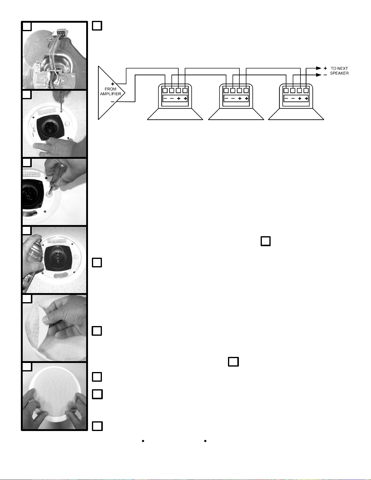
Using a Phillips screwdriver, open the screw on the wiring cover on the rear of the
speaker, slide open the cover, and remove the plug-in connector. Two (2) parallel “-“ terminals
and two (2) parallel “+” terminals are available for input wiring to the speaker and for output
wiring to the next speaker in the string. The wiring schematic for a typical 25V, 70V, or 100V
speaker system is shown in the diagram below:
7
For use in a speaker system without using the internal matching transformer, one cable should
run from the output of an 8 ohm maximum 25 watt amplifier to one ES-4T speaker only, or from
the output a 4 ohm maximum 50 watt amplifier to one ES-62T speaker only. Wiring the speaker
system in a series/parallel configuration may be acceptable depending upon the amplifier used,
but that wiring method is not covered in this installation manual.
8
Run the cable through the metal clamp strain relief and make the wiring terminations on the
plug-in connector. Plug the connector back in on the rear of the speaker, tighten the metal
strain relief clamp, and close the wiring cover.
NOTE: Lowell Manufacturing recommends that a suitable safety cable be attached from
the ring that is supplied on the rear of the speaker enclosure to the building structure. In
some areas of the country, building codes require this type of “safety cable” or
“earthquake cable”. Refer to applicable building codes for safety cable requirements.
9
10
11
For a tile ceiling installation the speaker is mounted to the tile and C-ring/rail assembly before
the wiring is terminated (as was already described in step ). At this point, place the
speaker/tile/C-ring assembly on the ceiling grid.
7
For a drywall ceiling installation, push the rear of the speaker through the hole in the
ceiling making sure that the mounting ears line up with the C-ring (and not with the gap in the
C-ring). Tighten the mounting ear screws with a Phillips screw driver so the ears rotate away
from the speaker body and clamp the speaker to the ceiling and the C-ring. WARNING: Do
not over-tighten the mounting ear screws or the plastic ears can break. As shipped from
the factory, the mounting ears can span a ceiling thickness of 1.25". The ears can be removed,
rotated 180 degrees, and placed back on the tightening screws and they will then be capable of
attaching to a ceiling thickness up to 2.125".
8
Using a flat blade screwdriver, set the transformer tap select switch on the desired position
(see the tap chart on the face of the speaker). Note: Do not use an 8W or 4W switch
position when using the speaker level output from a 25V, 70V, or 100V amplifier.
Note: If custom paint is not required, skip to step .
Use the plastic shipping cover as a paint shield and spray paint the front trim ring.
9
10
Carefully peel off the white scrim material before painting the grille. Spray paint the grille
with a few light coats being very careful not to clog the holes in the grille with paint. After the
paint on the grille is dry, replace the scrim using a light coat of all-purpose spray adhesive.
11
2
Press on the front grille until it is flush with the trim ring and the installation is complete.
11
Lowell Manufacturing Company
Phone: 800-325-9660
Fax: 636-257-6606 (www.lowellmfg.com)
100 Integram Drive
Pacific, Missouri 63069 U.S.A.
Printed on 11-18-13
Instruction Sheet:
IS-ES4T-ES62T
Page 2 of 2