

Lowell AMFM2 Installation Sheet
AMFM2
INSTALLATION SHEET
AND OPERATORS MANUAL
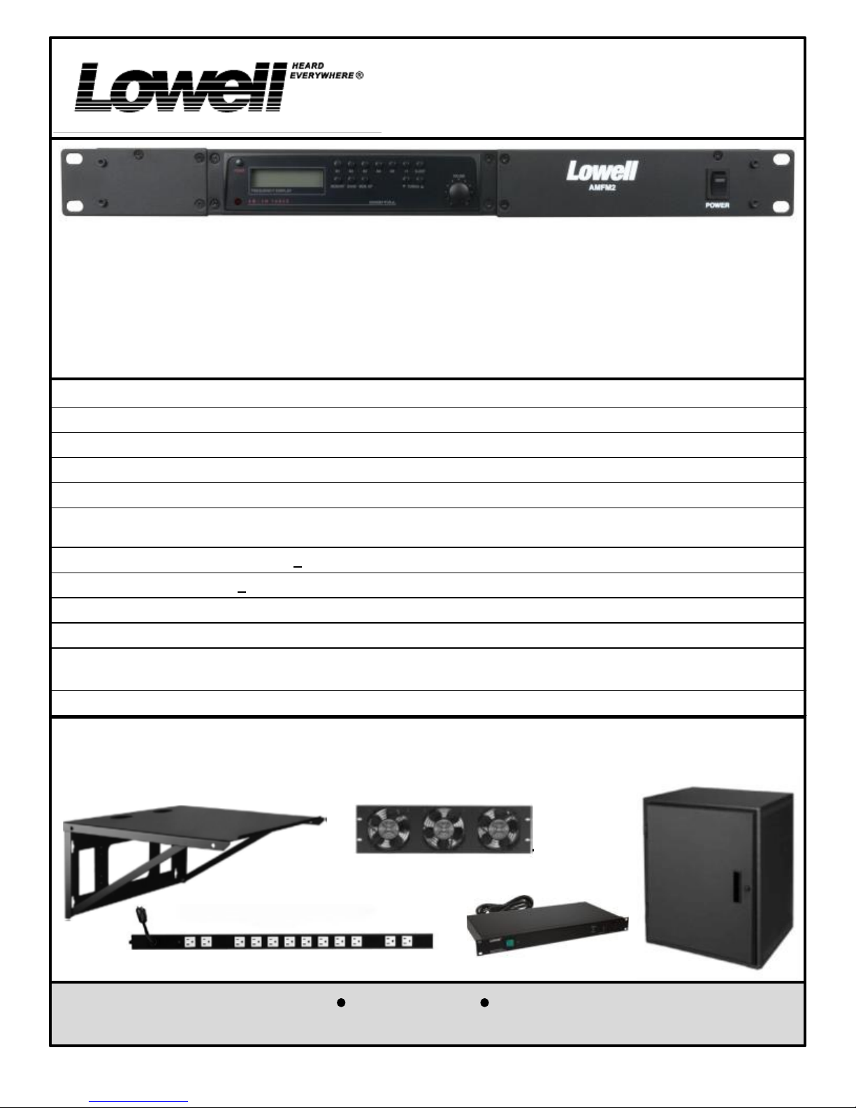
General Description:
The AMFM2 is a rack-mountable digital AM/FM stereo tuner featuring a large illuminated digital display with 10 AM
and 10 FM station presets, 14 day preset memory retention, and auto station search. The stereo/mono switch in
“Stereo Mode” provides stereo Hi-Z unbalanced line level outputs, or in “Mono Mode” provides dual mono Hi-Z
unbalanced line level outputs and an independent mono 8 ohm amplifier which will drive a monitor speaker or a
telephone system’s “Music-On-Hold”. A 12 VDC power connection is available for emergency back-up power or for
DC powered use in remote locations. An FM wire antenna is included and an “F” connector adapter is included for
the connection of coaxial cable from a remote FM antenna (coaxial cable and remote FM antenna not included). A
local AM loop antenna, a 2' RCA stereo to RCA stereo cable, and four (4) rubber stick-on feet are also provided.
1
Technical Specifications
AC Supply Voltage: 115VAC/230VAC (switchable) 50/60Hz, Power Consumption: 10W @ Rated Power
DC Supply Voltage: 12VDC, Power Consumption: 1.5A @ Rated Power
Tuning Range: FM : 87.5-108MHz, AM: 530-1710kHz,
Antenna Input: FM: 75W unbalanced coaxial, AM: 150W twin push terminals for AM loop antenna.
Stereo/Mono switch provides: Stereo Position; Stereo RCA jacks, unbalanced 0.775V @330WOutputs. (No MOH Out)
Mono Position; 2 Mono RCA jacks, unbalanced 0.775V @330W & Music-On-Hold Output: 8W 1W @ screw terminals.
Frequency Response: 50Hz-15kHz + 3dB
Total Harmonic Distortion: < 1% at 1kHz at rated power
Signal to Noise Ratio: FM: 60dB, AM: 45dB
Dimensions: 19" wide x 1.75" high x 9.5"deep (482mm wide x 44mm high x 240mm deep)
Weight: 7.25LBS. (3.29KGS)
Shipping Weight: 10LBS. (4.54KGS)
Color: Black
Optional Accessories (sold separately):
Lowell Manufacturing offers a full line of 19" equipment cabinets, wall mount shelves, rack mount AC power panels,
AC power strips, and cooling fans that can be used to install the Lowell Amplifier products.
See www.lowellmfg.com for product details.
Lowell Manufacturing Company
Call: 800-325-9660
100 Integram Drive Pacific, Missouri 63069 U.S.A.
Fax: 636-257-6606 Click: www.lowellmfg.com
1
REMOVABLE
PHOENIX
Instruction Sheet
CONNECTOR
IS-AMFM2
Issued: 2-18-15
Getting Started:
Please study carefully the “IMPORTANT SAFETY INSTRUCTIONS” that are given on page 4 before applying power
to your AMFM2 tuner.
INSPECTION
This unit was carefully checked and packed before leaving the factory. However, it is always a good idea to inspect
the shipping container and unit for indications of improper handling. If the unit has been damaged, make an
immediate claim to the dealer or distributor from whom it was purchased. If the unit was shipped to you, notify the
transportation company without delay, saving all packing materials, in order to process the claim.
INITIAL PERFORMANCE CHECK
Before installing the AMFM2 tuner, continue the inspection by running a quick performance check. With the stereo/
mono switch in the “MONO OUT & MOH OUT” position, connect an 8W test speaker to the 8W music-on-hold “MOH
OUT” terminals, attach the FM wire antenna, and set the controls for operation. MAKE SURE THE UNIT IS
GROUNDED BEFORE TESTING. In this way you can check the basic operation of the AMFM2 before actually
installing the unit and making all of the final terminations required for the permanent installation. If shipping damage
has resulted in the tuner being inoperable out of the box, call Lowell Customer Service to arrange for a replacement.
MOUNTING THE TUNER
The AMFM2 may be placed on a wall-mount shelf. For shelf mounting, attach the provided stick-on rubber feet to
the bottom of the AMFM2 chassis. Rack mount ears are built-into the front panel of the AMFM2, so the unit may be
mounted in a Lowell equipment cabinet using standard 10-32 Phillips-head machine screws (like the Lowell model
RS or RSP rack screws) with integral plastic washers to protect the finish of the front panel of the tuner.
POWER WIRING
The AC power cord provided with this tuner is equipped with a North American style NEMA 5-15P plug and the AC
1
VOLTAGE SELECT SWITCH (see item on page 3) is set to operate on a 115 VAC 50/60 Hz. power source. The
6
AMFM2 may also be powered with 12VDC (See the DC current requirements under “DC SUPPLY VOLTAGE” in the
“TECHNICAL SPECIFICATIONS” section on page 1). If this unit is to be used in other geo-political areas of the
world, it may be necessary to change the AC SUPPLY SWITCH to operate on 230 VAC. Remove the black screw
below “VOLTAGE SELECT” on the rear panel and push the switch in using a small diameter in sulated tool .
Remove the plug from the end of the cord and replace it with one appropriate for the local power grid receptacle
standards. The internal wire color code for the cord supplied with this unit is as follows:
Green/Yellow Earth “E” or Safety Ground
Blue Neutral “N”
Brown Lin e “L” or Hot
WARNING: THIS AMFM TUNER
MUST BE EARTH GROUNDED.
Note: If a British Standard BS1363 plug is installed, it must be provided with a 5 Amp fuse.
Since electrical color codes vary around the world, make sure that the correct connections are made to the cord
even if the local color code is different. If in doubt, obtain the services of a locally qualified electrical professional.
MAIN OUTPUT CONNECTIONS
On the rear panel of the AMFM2 is a Stereo/Mono switch. When this switch is in the “MONO
OUT & MOH OUT” position, RCA output jacks 1 and 2 provide the same mono output and the
Music-On-Hold (MOH) output is “ON”. W hen this switch is in the “STEREO OUT ONLY”
position, those same two RCA jacks (also marked L and R) provide a stereo output and the
Sleeve
Music-On-Hold (MOH) output is “OFF” (provides no output). The output cables connected to the
RCA output jacks should be wired with the pin “hot” or “+” and with the sleeve “common” or “-”.
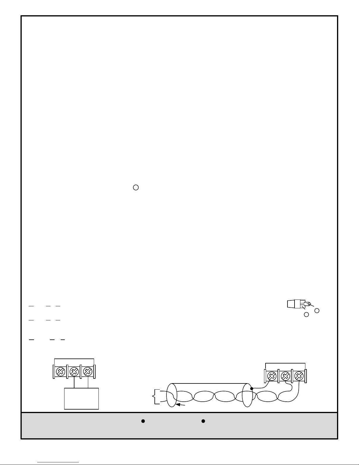
MUSIC-ON-HOLD (MOH) OUTPUT
The MOH 8W 1 watt output can drive a monitor speaker or the Music-On-Hold input of a telephone system.
MOH OUT
G COM
8W
_
+
MONITOR
SPEAKER
Lowell Manufacturing Company
Call: 800-325-9660
Fax: 636-257-6606 Click: www.lowellmfg.com
Shielded wiring from the MOH output to the
telephone system MOH input is typically not
required, but if shielded wiring is used, drain the
shield at the MOH output and butt the shield (no
Telephone
System
MOH
Input
connection) at the telephone system.
600W Twisted-Pair Wiring
BUTT SHIELD (No connection)
DRAIN
SHIELD
100 Integram Drive Pacific, Missouri 63069 U.S.A.
MOH OUT
G COM 8W
Instruction Sheet
REMOVABLE
Issued: 2-18-15
CONNECTOR
2
Pin
+
_
IS-AMFM2
PHOENIX
 Loading...