

Lowell ACR-SEQ6-2009 Specifications
Spec No. 1607 | Rev. 04.25.16 | pg. 1/2
Heard Everywhere Since 1947
Model No.
ACR-SEQ6-2009
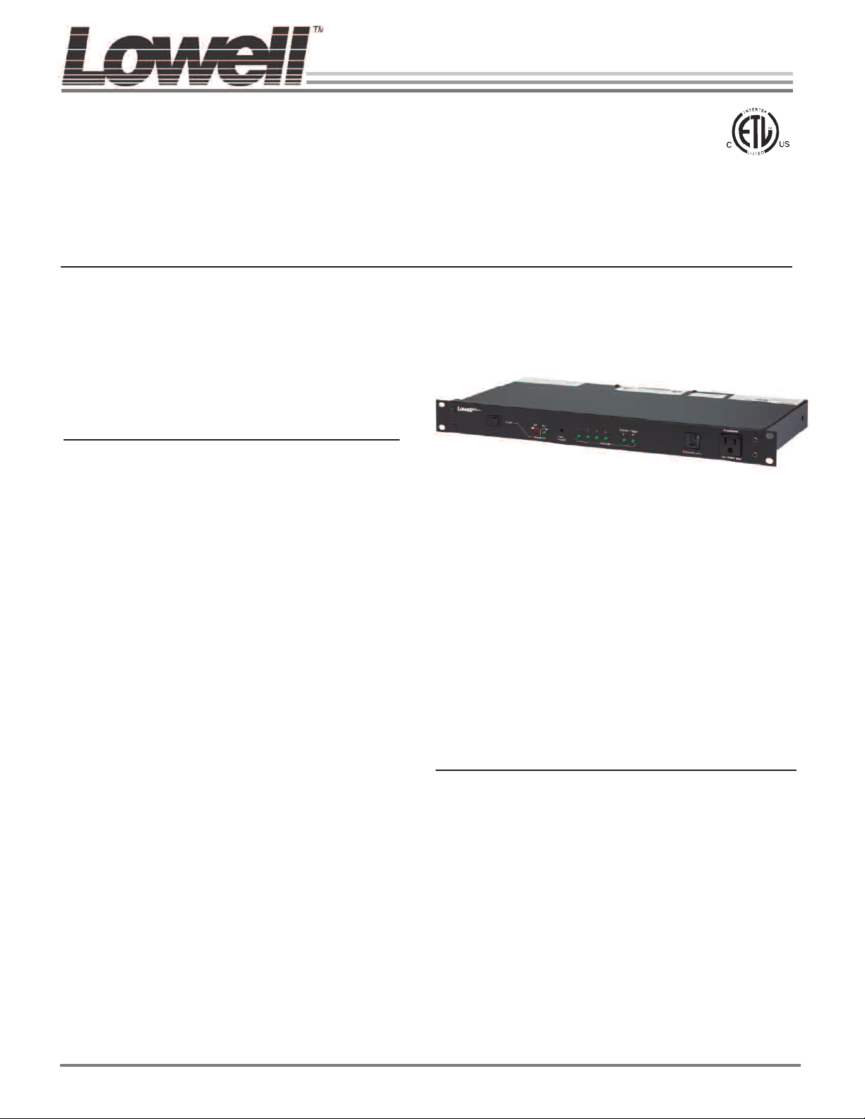
Rackmount panel with 9 outlets & sequencer
19”W rackmount panel with four step sequential power
and nine outlets (six switched, three unswitched) for sequential activation/deactivation of connected equipment.
Includes alarm interface.
Features
• Delay between sequenced steps (0.5-10 seconds) is
screwdriver adjustable
• Power rating of 120VAC, 60Hz/20A with EMI/RFI filtering. Each receptacle rated 15A.
• Rear termination blocks accommodate remote
switches, external triggers and an alarm system interface for use where mandated by fire code.
• Includes two dry contact closures (steps 5 and 6) for
triggering remote power control units (RPC series,
order separately).
• Actuation Switch: front panel rocker switch with mo-
mentary contacts (normally open SPST) plus rear
barrier strip termination blocks for momentary (normally open) remote switches.
• Alarm Interface: lock on, lock off and switch lock func-
tions for alarm system or master control panel applications.
• External Control Connections: plug-in barrier strip
terminal blocks
• EMI/RFI Filter: 19dB@500kHz, 42dB@30MHz
• Termination via 9 ft. attached cord with NEMA 5-20P
plug.
• Dimensions: 19"W x 1.75"H (1U) x 9"D
• Made in the U.S.A.
• ETL-listed in the U.S. and Canada to UL Standard
60065
A & E Specifications
The sequential AC rackmount power panel shall be Lowell
Model No. ACR-SEQ6-2009. It shall be ETL listed and have
a power rating of 120VAC 60Hz/20A with EMI/RFI filtering,
9 outlets (6 switched, 3 unswitched) and 2 steps providing
contact closures to sequentially activate/deactivate equipment (4-6 steps) with a sequence delay of 0.5 to 10 seconds. It shall be housed in a 1U steel rackmount chassis
measuring 19"W x 1.75"H x 9"D and having color-coded
LEDs. Activation shall be via a rocker switch on the front
panel.
Lowell makes every effort to provide accurate information while reserving the right to change specifications and/or improve manufacturing methods without notification.
©2016 Lowell Manufacturing Company, 100 Integram Dr., Pacific MO 63069 | tel. 800.325.9660 | www.lowellmfg.com
Spec No. 1607 | Rev. 04.25.16 | pg. 2/2
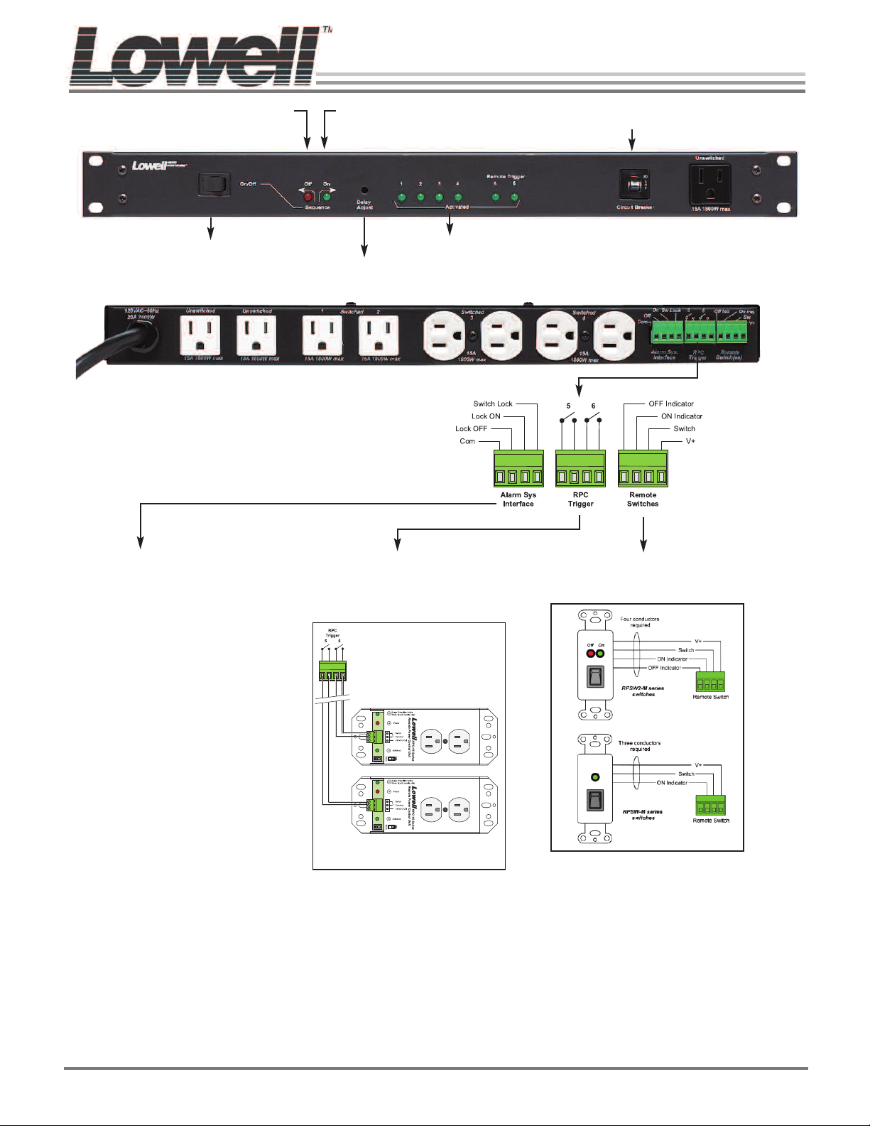
FLASHING = Down cycle in progress.
Red LED
STEADY ON = Down cycle completed (system off).
Rocker switch
activation
Includes 9-ft. attached cord
with NEMA 5-20P plug.
Green LED
FLASHING = Up cycle in progress.
STEADY ON = Up cycle completed (system on).
Green LEDs – Indicate progress
Delay – recessed trim pot
of UP and DOWN sequence
with screwdriver adjust
Circuit Breaker
Rear view
ALARM SYSTEM INTERFACE
If required by local building code, facility usage,
or the Fire Marshal; the system switches can
be overridden and the system controlled by
contact closures provided by the fire alarm
panel or other control system. A maintained
contact between the “com” terminal and any of
the terminals shown here will provide the following functions.
Lock Off: A maintained contact between the
“COM” terminal and the “LOCK-OFF” terminal
will turn the system off and keep it off regardless of other switch activations. If the system is
already off, it will be kept off.
Lock On: A maintained contact between the
“COM” terminal and the “LOCK-ON” terminal
will turn the system on and keep it on regardless of other switch activations. If the system is
already on, it will be kept on.
Switch Lock: A maintained contact between
the “COM” terminal and the “SWITCH-LOCK”
terminal will lock the system in its current state,
either on or off, regardless of any other switch
activations.
Caution: Do not allow alarm system to make
more than one of the contacts described above
at the same time. Controller board damage
may result.
Maximum wire distances
24ga: 20,000 ft (approx. 3.5 miles), 22ga.: 31,200 ft.
(approx. 5.5 miles), 18ga.: 76,800 ft. (approx. 13.5 miles)
RPC TRIGGER CONNECTIONS REMOTE SWITCH CONNECTIONS
Multiple RPC series remote power control
units can be connected to outputs 5 and 6 (60
Connect a maximum of 5 remote MOMENTARY
switches. Order switches separately.*
max. each, dependent upon limits of electrical
panel). Order RPC units separately.
RPC series remote
power controls.
* See MOMENTARY switches:
• with 2 LEDs: RPSB2-MP, RPSB2-MKP, RPSW2-MP, RPSW2-
• with 1 LED: RPSB-MP, RPSB-MKP, RPSW-MP, RPSW-MKP,
Four conductors (2 LED switch).
Three conductors (1 LED switch).
MKP, RPSB2-MR, RPSB2-MKR
RPSB-MR, RPSB-MKR
Lowell makes every effort to provide accurate information while reserving the right to change specifications and/or improve manufacturing methods without notification.
©2016 Lowell Manufacturing Company, 100 Integram Dr., Pacific MO 63069 | tel. 800.325.9660 | www.lowellmfg.com
 Loading...