

Page 1
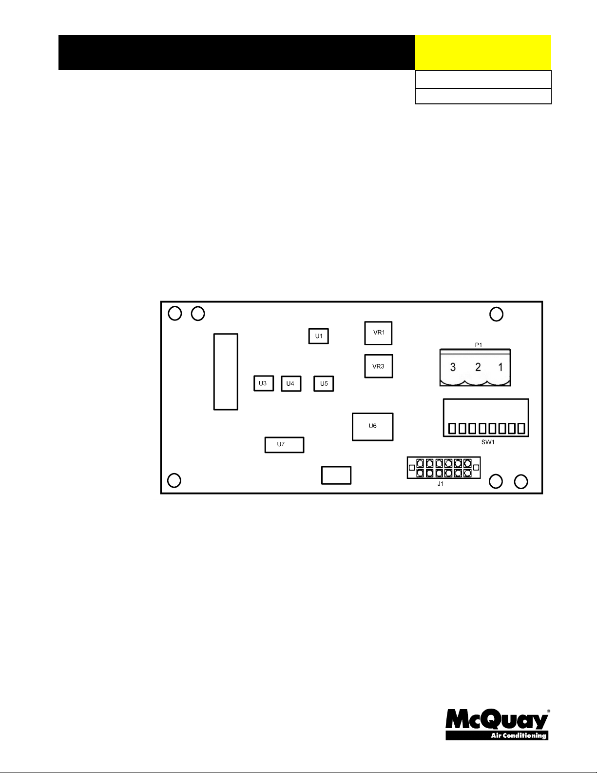
Installation and Maintenance Manual
Group
Date
MicroTech II™
AAF®HermanNelson® Unit Ventilator Controller
N2 Open Communication Modules
IM 730-1
: McQuay Controls
: July 2002
© 2002 McQuay International
Page 2

Contents
GENERAL INFORMATION.............................................................................................................4
ESCRIPTION
D
PPLICATION
A
OMPONENT DATA
C
......................................................................................................................................4
......................................................................................................................................5
.............................................................................................................................5
N2 Network Connection ................................................................................................................5
Address Switch ..............................................................................................................................6
Dip switch settings and how they work.....................................................................................................6
12-Pin Header...............................................................................................................................6
INTEGRATION..................................................................................................................................7
ONFIGURING THE UNIT CONTROLLER
C
ETWORK CONNECTION
N
.....................................................................................................................7
...............................................................................................7
N2 Open Addressing......................................................................................................................7
N2 Bus Information.......................................................................................................................7
Selecting the Right Cable ..............................................................................................................7
N2 Bus Rules .................................................................................................................................8
Number of Devices ........................................................................................................................8
Line Length and Type....................................................................................................................8
INSTALLATION.................................................................................................................................9
To mount a new MicroTech II N2 communication module onto the Unit Controller board, follow
these steps: .................................................................................................................................... 9
To replace a MicroTech II N2 communication module on a MicroTech II Unit Controller board,
follow these steps:..........................................................................................................................9
SERVICE INFORMATION.............................................................................................................12
Figures
EST PROCEDURES
T
IST OF REPLACEABLE PARTS
L
...........................................................................................................................12
..........................................................................................................12
Network Connection Plug............................................................................................................12
Generic Replacement Parts......................................................................................................................12
Direct Replacement Parts ........................................................................................................................12
Kit................................................................................................................................................12
IGURE
F
IGURE
F
IGURE
F
IGURE
F
IGURE
F
IGURE
F
IGURE
F
IGURE
F
IGURE
F
COMMUNICATION MODULE
1: N2
ICROTECH
2. M
DDRESS SWITCH
3. A
IP SWITCH VALUES (WHEN CLOSED
4. D
DDRESS SWITCH
5. A
6. N2 B
7. C
8. C
9. N2
US RULES
OMMUNICATION MODULE MOUNTED ON THE UNIT CONTROLLER BOARD
OMMUNICATION MODULE MOUNTING DETAIL
MODULE TYPICAL WIRING
COMMUNICATION MODULE MAJOR COMPONENTS
II N2
(S1)...........................................................................................................6
SET TO EXAMPLE
(S1)
......................................................................................................................8
..............................................................................................5
).....................................................................................6
...............................................................................6
....................................................................11
...............................................................................................11
....................................5
..........................10
2 IM 730-1
Page 3

Limited Warranty
Consult your local McQuay Representative for warranty details. Refer to Form 933-43285Y. To find
your local McQuay Representative, go to www.mcquay.com.
Revision History
IM 732 August 1, 2002 Initial Release
Reference Documents
Number Source Title
OM748 www.McQuay.com Air Source Heat Pum p with Electric Heat (Software Model 00)
OM749 www.McQ uay.com Water Source Heat Pump with Electric Heat (Sof tware Model 02)
OM750 www.McQuay.com DX Cooling wi th Electric Heat (Software Model 04)
OM751 www.McQuay.com DX Cooling Only (Software Mo del 05 )
OM752 www.McQuay.com Electric Heat Onl y (Software Model 06)
OM753 www.McQ uay.com DX Cooling with Wet Heat - Valve Control (Software Model 07)
OM754 www.McQ uay.com 2-pipe Wet Heat Only - Valve Co ntrol (Software Model 09)
OM755 www.McQuay.com 2-pipe Hea t/Cool - Valve Contr ol (Software Model 11 )
OM756 www.McQuay.com 4-pipe Hea t/Cool - Valve Contr ol (Software Model 13 )
OM757 www.McQuay.com 2-pipe Coo ling Only - Valve Control (Software Model 15)
OM758 www.McQuay.com 2-pipe Coo ling wi th Electric Heat - Valve Control (Software Mod el 17)
ED 15069 www.McQuay.com MicroTech II™ Unit Ventilator Unit Controller
ED 15065 www.McQuay.c om Micr oTech II™ AAF®-HermanNelson® Unit Ventilator U nit Control ler Protocol
IM731 www.McQuay.c om Micr oTech II™ AAF®HermanNelson® U nit Ve ntilator Co ntroller BACnet®
IM747 www.McQuay.com MicroTech II™ Unit Ventilator Unit Controls Insta llation Manual
www.johnsoncontrols.com/Metasys/n2open.htm N2 -- A Data Communication Protocol for Building Automation and
Water Source Heat Pump without Electric Heat (Software Model 03)
DX Cooling with Wet Heat - F&BP Damper Control (Software Model 08)
2-pipe Wet Heat Only - F&BP Damper Control (Software Model 10)
2-pipe Heat/Cool - F&BP Damper Control (Software Model 12)
4-pipe Heat/Cool - F&BP Damper Control (Software Model 14)
2-pipe Cooling Only - F&BP Damper Control (Software Model 16)
2-pipe Cooling with Electric Heat - F&BP Damper Control (Software Model 18)
Protocol Implementation Conformance Statement
Information
Communication modules
Control Networks
Notice
Copyright © 2002 McQuay International, Minneapolis MN All rights reserved throughout the world
™ The following are trademarks or registered trademarks of their respective companies: N2 Open from Johnson Controls Corporation,
Protocol Selectability, MicroTech II, and AAF-HermanNelson from McQuay International.
IM 730-1 3
Page 4
General Information
Use this manual to physically install the communication module onto the Unit Ventilator Unit
Controller board and to make the wiring connections to your network. You also need the appropriate
McQuay Engineering Data Sheet known as the Protocol Information to integrate the unit into your
network. The Protocol Information contains addressing details, N2 Open protocol information, and a
list of the data points available to the network. See the Reference Documents section of this document
for part numbers of Protocol Information manuals. These documents are available from your local
McQuay International representative and for downloading at the McQuay International web site:
www.mcquay.com.
Electric shock hazard. Can cause personal injury or equipment damage.
This equipment must be properly grounded. Only personnel that are knowledgeable in the
operation of the equipment being controlled must perform connections and service to the
MicroTech II control panel.
Static sensitive components. Can cause equipment damage.
WARNING
!
CAUTION
!
Description
Discharge any static electrical charge by touching the bare metal inside the control panel
before performing any service work. Never unplug cables, circuit board terminal blocks, or
power plugs while power is applied to the panel.
NOTICE
This equipment generates, uses and can radiate radio frequency energy and, if not installed
and used in accordance with this instruction manual, may cause interference to radio
communications. It has been tested and found to comply with the limits for a Class A digital
device, pursuant to part 15 of the FCC rules. These limits are designed to provide reasonable
protection against harmful interference when the equipment is operated in a commercial
environment. Operation of this equipment in a residential area is likely to cause harmful
interference in which case the user will be required to correct the interference at his or her
own expense.
interference or for the correction thereof.
McQuay International disclaims any liability resulting from any
A MicroTech II N2 Open communication module incorporates a MicroTech II Unit Controller into an
N2 Open Local Area Network (LAN). This combination provides an interface to the buildingautomation network.
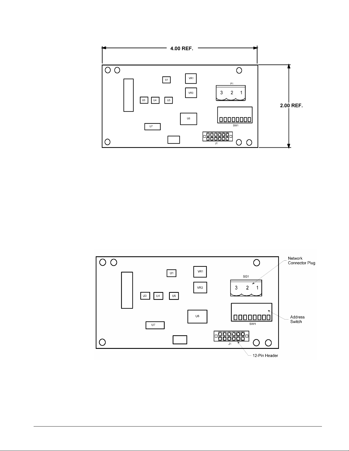
The MicroTech II N2 communication module is a printed-circuit board that plugs onto the MicroTech
II Unit Controller board. Figure 1 shows an outline drawing of the N2 communication module with
reference dimensions.
4 IM 730-1
Page 5
Application
Figure 1: N2 communication module
The MicroTech II N2 communication module connects the MicroTech II Unit Controller to the
Building Automation System (BAS) on a N2 Local Area Network. It is the interface for the exchange
of N2 points between the network and the Unit Controller.
Component Data
Figure 2 shows the major components of the communication module.
Figure 2. MicroTech II N2 communication module major components
N2 Network Connection
N2 network wiring connec t ions are made to SG1 (Network Connector Plug). This connector is
physically made in two parts, a board-mounted (3-terminal) male plug and a (3-terminal) female plug
with screw-type wiring connections.
IM 730-1 5
Page 6
The two portions come plugged together and look like a single part. However, they can be
separated at the middle by gently pulling them apart. Connect the wiring (that has been
stripped of insulation by about 1/3-inch) to the SG1 female plug portion. Insert the wires into
the proper screw-terminals and tighten the connections with a small flat-blade screwdriver
(see
Figure 9). Make sure that the wiring connections aren't shorted and that they are tight.
Address Switch
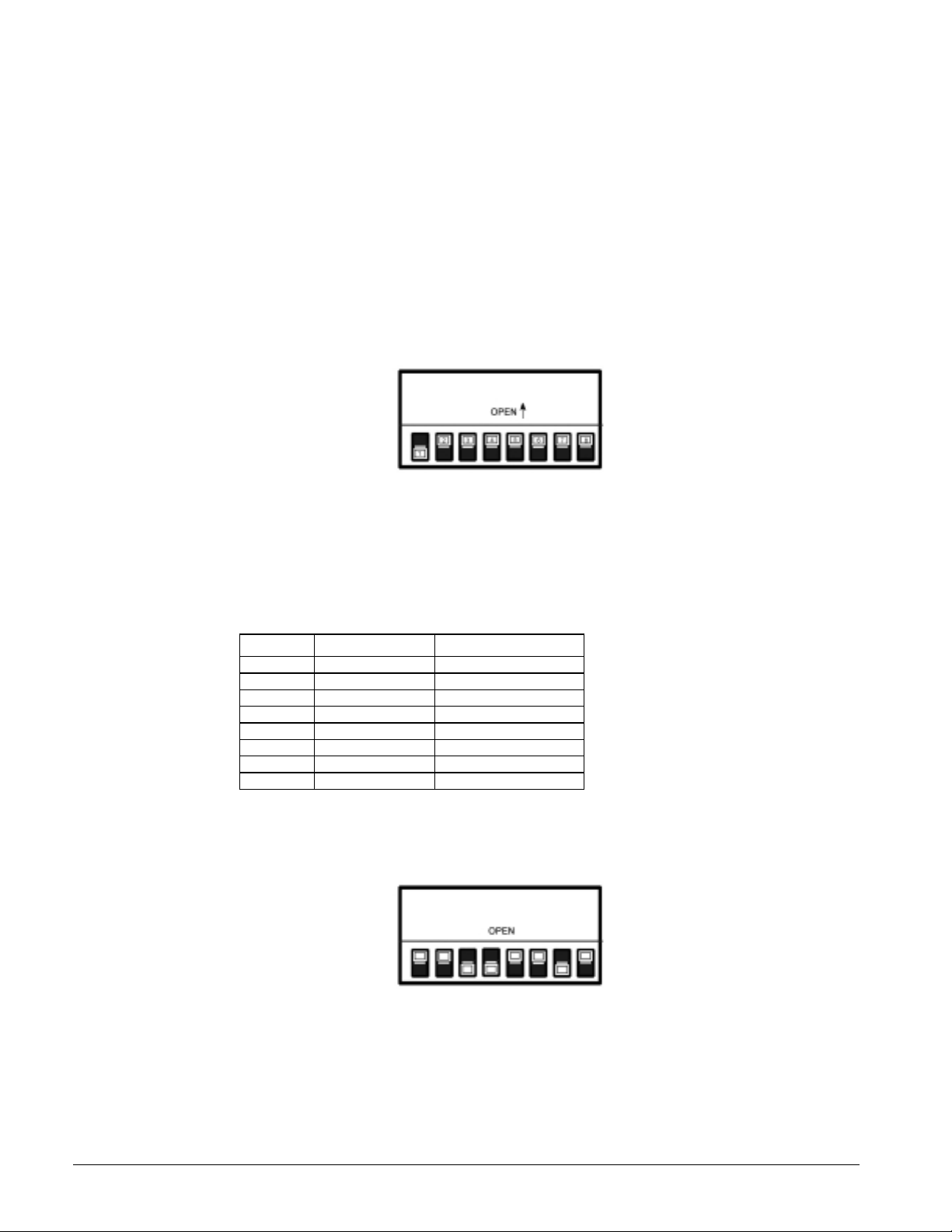
The Address Switch (S1) must be field-configured on each MicroTech II N2 communication module
to a unique address, so that it can be located and addressed when wired into the network. The system
integrator usually pre-assigns an address to each module. The available range of possible addresses
using the binary switches is 1 through 253.
Figure 3. Address switch (S1)
Dip switch settings and how they work
When a switch is in the up (open) position, its value is 0. So when all the switches are in the up there
is no module address. When switches are set in the down (closed) position, their individual values are
shown in Figure 4 below.
Figure 4. Dip switch values (when closed)
Switch # Value Numb er when closed
1 2 to the zero power 1
22 to the 1
32 to the 2
4 2 to the 3rd power 8
52 to the 4
62 to the 5
72 to the 6
82 to the 7
st
power 2
nd
power 4
th
power 16
th
power 32
th
power 64
th
power 128
Figure 5 shows an example of a typical address setting. The digital switch positions as read from left
to right are 00110010. This provides an address of 76 as illustrated below.
Figure 5. Address switch (S1) set to example
(0 + 0 + 4 + 8 + 0 +0 +64 +0 =76)
12-Pin Header
The 12-pin header, J1, connects the unit-controller Unit Controller board to the MicroTech II N2
Open communication mod ule through the bottom side of the printed-circuit board.
6 IM 730-1
Page 7

Integration
Configuring the Unit Controller
Each MicroTech II Unit Controller board and N2 communication module is preprogrammed and
configured at the factory to be a single Unit Controller, whether the boards are assembled together at
the factory or field assembled. Each unit is also ready to operate using the default values. These
default values may be changed via the unit’s keypad, using ServiceTools™, or via the network. See
the appropriate operation manual for default values and keypad operating instructions, and refer to the
appropriate MicroTech II Protocol Information for descriptions of the network variables. See
Reference Documents for part numbers.
Network Connection
N2 Open Addressing
The N2 Open device address of the MicroTech II controller in a Local Area Network (LAN) is set by
using the eight-position DIP switch on the N2 communication module (see the heading: Address
Switch). The address is physically set using the binary switches. An open switch (switch up) is a 0,
and the value of a closed switch (switch down) is shown in Figure 4. The address naming starts with
switch 1. Each address must be unique and set during installation. After setting the address with the
switches, you must cycle power to the controller (turn the controller off and then on again) for the
new address to take effect.
The data transmission rate is 9600-bps (baud)..
N2 Bus Information
The N2 communication Bus is a local network that links controllers and point interfaces to the
Network Control module (NCM). The N2 Bus uses a master/slave protocol in which the master
device (the NCM) initiates all communication with the N2 Bus devices. These N2 Bus devices
include the Digital Control modules (DCMs), Point Multiplex modules (XBN, XRE, XRL, XRM),
and all Application Specific Controllers (ASCs).
The N2 Bus is wired in a daisy-chain fashion and the devices are connected in series. The N2 Bus can
use solid or stranded wire, or optical fiber when special fiber modems are used. So the choices
include:
• 3-wire twisted cable
• 2-wire twisted-pair telephone cable
• 2-wire twisted-pair cable with a shield
• Duplex optical fiber (requires a pair of fiber modems).
Selecting the Right Cable
For most N2 Bus installations, the most practical choice is solid, 2-wire twisted-pair, unshielded,
telephone cables. If you have existing stranded cable, you can use it, but you may find that the strands
become a nuisance when wiring the cable.
For N2 Bus installations where there is a lot of electrical noise (e.g., gas ignition systems, radar or
magnetic-resonance imaging equipment, on a factory floor, or outdoors), shielded wire or optical
fiber is the best choice. Of the two, fiber is by far the better option, but it is more expensive. It offers
extended N2 distances and excellent immunity to electrical noise, lightning, and various other
building noises. It can also be buried underground between two buildings so that the N2 Bus can be
extended in a campus-type installation.
IM 730-1 7
Page 8
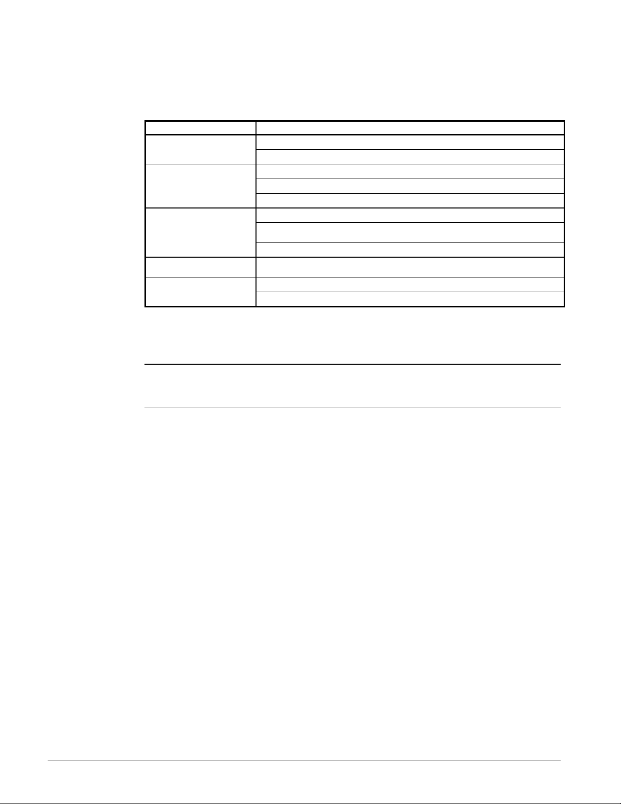
N2 Bus Rules
Figure 6 summarizes the rules and maximums allowed for installing the N2 Bus. You may wish to
print this table and keep it handy.
Figure 6. N2 Bus Rules
Category
General
Number of Devices
Line Length and Type
Cable
Terminations
Number of Devices
Rules/Maximums Allowed
One or two N2 Bus per NCM
Only daisy-chained devices
100 devices per NCM (60 to 200 TC-9100s)
50 devices per repeater
Two repeaters cascaded
1524 m (5000 ft) between NCM to farthest N2 device before repeater is needed
4572 m (15,000 ft) from NCM to farthest N2 device (three segments of 1524 m [5000 ft]
each)
2012 m (6600 ft) between two fiber modems
26 AWG twisted pair or larger
(solid or stranded 22 AWG or heavier recommended)
Two switched EOL per segment (preferred)
One switch ed EOL per segment (required)
• Currently, up to 100 devices can be connected to an NCM, including repeaters. The actual
number of devices is dependent on the features and point count used in the NCM.
Note:
The number of devices varies because both the number of software objects and JC-BASIC
processes influence the Network Controller’s (NC’s) performance (see Guidelines for
Efficient Operation Technical Bulletin [LIT-636341]).
• Up to 50 daisy-chained devices are allowed before a repeater is needed. Add a repeater to the bus
when you reach 49 devices. Count each repeater as one device.
• Any path from the NCM to an N2 device cannot go through more than two repeaters or two pairs
of fiber modems (i.e., cascaded repeaters/modems). This is because the repeater/modem delays
the N2 Bus signal between Sides A and B. The N2 Bus can compensate for only two of these
delays; therefore, up to two repeaters or two pairs of fiber modems can be cascaded in series.
Note that the signal from the NCM only passes through two r epeaters or two pa i rs of modems to
any N2 device.
• For additional information on the maximum number of devices and priority assignments, be sure
to read Guidelines for Efficient Operation Technica l Bulletin (LIT-636341).
Line Length and Type
• A repeater is required for every 1524 m (5000 ft) of daisy-chained cable.
• The maximum distance between an NCM and the farthest device (even through repeaters) i s
4572 m (15,000 ft).
• You may use 18 through 26 AWG twisted pair wire; however, Johnson Controls recommends 22
AWG or heavier, because lighter wire breaks easily when stripped and installed.
• The maximum distance between two fiber modems is 2,012 m (6,600 ft). If your application
requires lengths beyond that, contact S.I. Tech for information about their “high power” option.
You may also use optical fiber on the N2 Bus (a pair of fiber modems is required for conversion).
Duplex optical fiber is needed, either 50 (3.0 dB/km), 62.5 (4.0 dB/km), or 100 (5.0 dB/km)
micrometers. The 62.5 size is preferred.
8 IM 730-1
Page 9

Installation
The MicroTech II N2 Open communication module may either be installed in the factory or field
installed. The module mounts on connector pins and is held in place with three plastic locking
standoffs. The N2 Open network connects to the MicroTech II N2 Open communication module at
the network connec t or plug (SG1).
The MicroTech II N2 Open communication module is included in a kit (part number
You need to know the N2 address that is assigned to the communication module. The network
administrator can supply this information.
107293125
).
To mount a new MicroTech II N2 communication module onto the Unit
Controller board, follow these steps:
1. Disconnect power from the Unit Controller board.
2. Unplug the unwired network cable connector from the terminal block SG1 (see Figure 2).
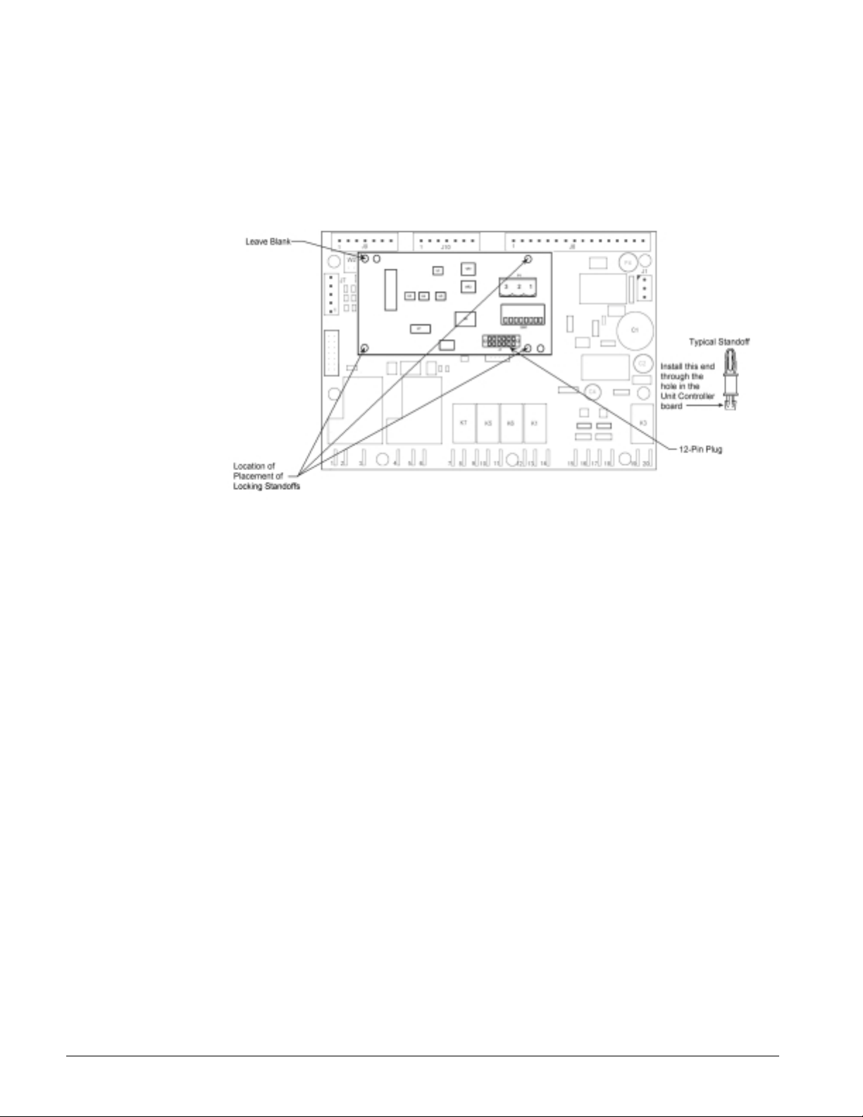
3. Install the three standoffs on the Unit Controller board at the locations shown in Figure 7 Simply
press the locking standoffs into the holes on the board. Then locate the empty connector for the
MicroTech II N2 communication module on the Unit Controller board (see Figure 8).
4. Orient the communication module printed-circuit board so that the component side faces outward
and the connector pins can penetrate the 12-pin header on the communication module.
5. Push the communication module onto the connector pins and standoffs until you hear the faint
click of the locking standoffs securing the board in place.
onnect the network wiring to the network cable connector and plug it into the terminal block,
6.
C
SG1, on the MicroTech II communication module (see Figure 9).
7. Set the N2 address (supplied by the network administrator) using the Address Switch (SW1). The
valid range is 1 to 253 (see Figure 4).
8. Reapply power to the MicroTech II Unit Controller board.
Note:
You must maintain the polarity of the signal througho ut the network. Always connect + to +
and – to –. Also, the network cable shield or third-wire connection must be continuous
throughout the net wor k and must be connected to earth ground at
(and only one) point.
one
To replace a MicroTech II N2 communication module on a MicroTech II
Unit Controller board, follow these steps:
1. Disconnect power from the Unit Controller board.
2. Record the N2 address on the Address Switch (SW1).
3. Remove the network cable plug-in connector from the SG1 terminal block (see Figure 2).
4. Locate the three standoffs for the MicroTech II N2 communication module on the Unit
Controller board (Figure 7 and Figure 8).
5. Using a pliers or screwdriver to depress the barb on one standoff, gently pull the corner of the
communication module over the barb. Be careful to not bend the communication module or
misalign the connector pins.
6. Proceeding to the other two corners, remove the communication module from each standoff, and
pull the module over the standoffs.
7. Gently lift the MicroTech II N2 communication module from the Unit Controller board.
8. Locate the empty connector pins and three standoffs for the MicroTech II N2 communication
module on the Unit Controller board.
9. Orient the communication module printed-circuit board so that the component side faces outward
and the connector pins can penetrate the 12-pin header on the communication module.
10. Push the communication module onto the connector pins and standoffs until you hear the faint
click of the locking standoffs securing the board in place.
IM 730-1 9
Page 10
11. Connect the communication module to the network by reinserting the network-cable plug into
SG1 (see Figure 9).
12. Set the N2 Address in Address Switch SW1 (see Figure 4).
13. Reapply power to the MicroTech II Unit Controller board.
Figure 7. Communication module mounted on the Unit Controller board
10 IM 730-1
Page 11
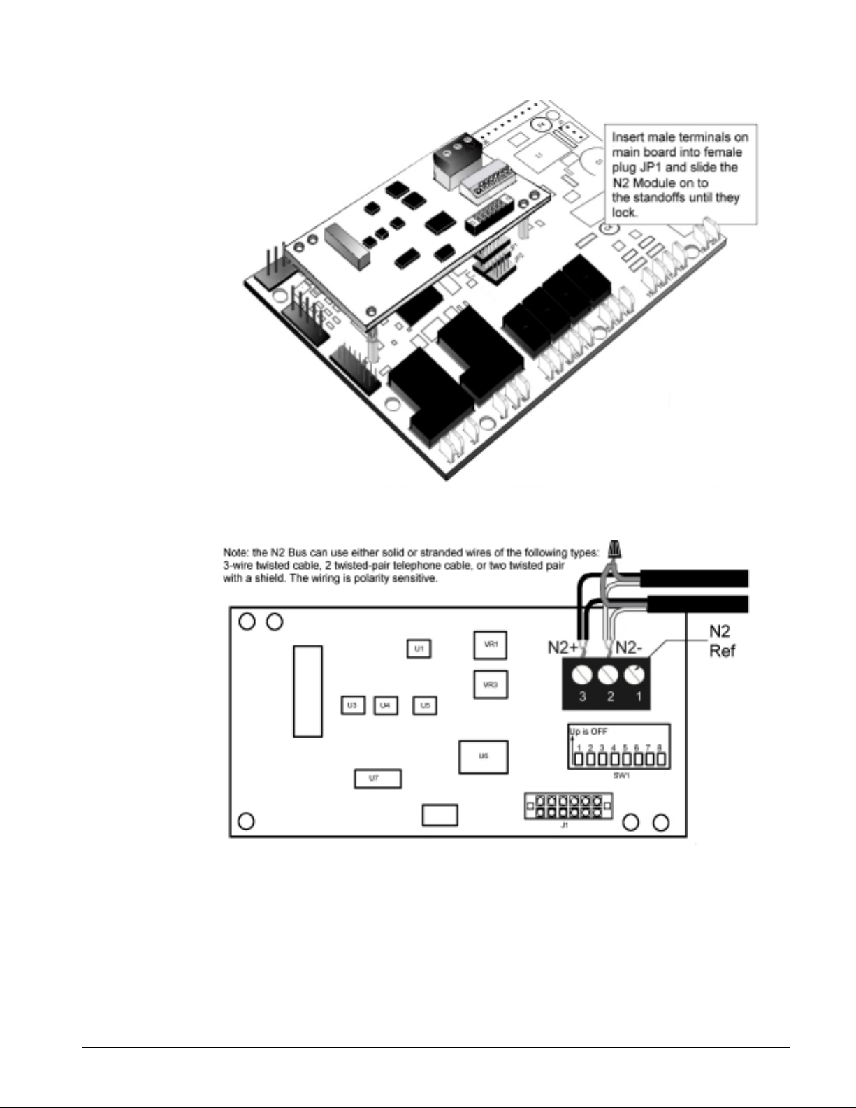
Figure 8. Communication module mounting detail
Figure 9. N2 module typical wiring
IM 730-1 11
Page 12
Service Information
Test Procedures
If you can control the unit from the keypad but are unable to communicate with it via the network, try
the following:
• Verify the network (bus) wiring
• Check the integrity of the cable harness to the network terminals
• Verify that the N2 address (SW1) is set to a unique binary number between 1 and 253.
If the MicroTech II N2 Open communication module still doesn’t respond, replace the
communication module.
List of Replaceable Parts
Network Connection Plug
Generic Replacement Parts
The three-contact network connector plug has custom markings, but if you lose this terminal block
you can replace it with a standard block without the markings from a manufacturer. The list below
contains manufacturers part numbers for equivalent parts witho ut the custom markings.
Manufacturer Telephone Order Number
Phoenix Contact (800) 888-7388 17 57 02 2
Altech Corp (908) 806-9400 37.003
Direct Replacement Parts
You can order direct replacement parts for these connector plugs from McQuay International
(1-800-37-PARTS).
Part Number Description
AS-TBKIT-0 5 terminal blocks marked REF, N2- and N2+
Kit
Component Description Part No.
Kit N2 communication module for unit ventilators with standoffs 107293125
13600 Industrial Park Boulevard, Minneapolis, MN 55440 USA (763) 553-5330 (www.mcquay.com)
 Loading...