

Lowara e-SVE, VME, e-HME, e-LNEEE, e-LNESE Installation, Operation And Maintenance Manual
...Page 1
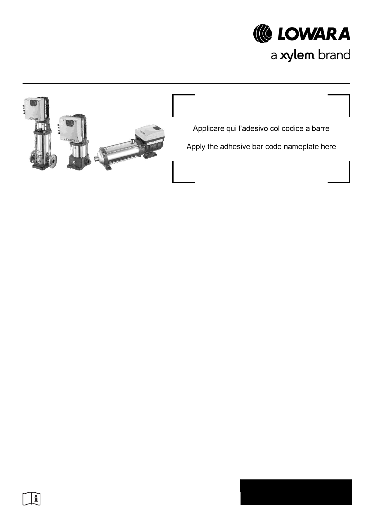
Smart Pump Range
Installation, operation
and maintenance manual
e-SVE VME e-HME
Software Version 101.04
Cod.001080136EN rev.D ed.02/2018
Page 2

en – Original instructions
Table of Contents
1 Introduction and Safety ............................................................................................................................................ 5
1.1 Introduction ........................................................................................................................................................ 5
1.2 Safety ................................................................................................................................................................ 5
1.2.1 Danger levels and safety symbols ................................................................................................................ 5
1.2.2 User safety .................................................................................................................................................... 6
1.2.3 General safety rules ...................................................................................................................................... 7
1.2.4 Protection of the environment ....................................................................................................................... 8
1.2.5 Sites exposed to ionizing radiations .............................................................................................................. 8
1.3 Spare parts ........................................................................................................................................................ 8
1.4 Product warranty ............................................................................................................................................... 8
2 Transportation and Storage ..................................................................................................................................... 9
2.1 Unit handling ..................................................................................................................................................... 9
2.2 Storage ............................................................................................................................................................ 10
3 Technical Description ............................................................................................................................................... 11
3.1 Designation ..................................................................................................................................................... 11
3.2 Data plates ...................................................................................................................................................... 11
3.2.1 Motor ........................................................................................................................................................... 11
3.2.2 Pump ........................................................................................................................................................... 12
3.3 Design and layout............................................................................................................................................ 15
3.4 Intended use .................................................................................................................................................... 16
3.4.1 Application alternatives ............................................................................................................................... 16
3.5 Improper use ................................................................................................................................................... 16
4 Installation ............................................................................................................................................................... 17
4.1 Mechanical installation .................................................................................................................................... 17
4.1.1 Installation area ........................................................................................................................................... 17
4.1.2 Unit installation ............................................................................................................................................ 17
4.1.3 Outdoor unit installation .............................................................................................................................. 18
4.2 Hydraulic installation ....................................................................................................................................... 19
4.3 Electrical Installation ....................................................................................................................................... 20
4.3.1 Electrical requirements ................................................................................................................................ 20
4.3.2 Wire types and ratings................................................................................................................................. 21
4.3.3 Power supply connection ............................................................................................................................ 22
5 Operation ............................................................................................................................................................... 25
5.1 Wait times ........................................................................................................................................................ 25
6 Programming ......................................................................................................................................................... 26
6.1 Control panel ................................................................................................................................................... 26
6.2 Description of the buttons ............................................................................................................................... 27
6.3 LEDs description ............................................................................................................................................. 27
6.3.1 POWER (power supply) .............................................................................................................................. 27
2
Page 3

en – Original instructions
6.3.2 STATUS ...................................................................................................................................................... 27
6.3.3 SPEED (speed bar) ..................................................................................................................................... 27
6.3.4 COM (communication) ................................................................................................................................ 28
6.3.5 Unit of measurement ................................................................................................................................... 28
6.4 Display ............................................................................................................................................................. 29
6.4.1 Main visualization ........................................................................................................................................ 29
6.4.2 Parameters menu visualization ................................................................................................................... 29
6.4.3 Alarms and errors visualization ................................................................................................................... 30
6.5 Software parameters ....................................................................................................................................... 30
6.5.1 Status Parameters ....................................................................................................................................... 31
6.5.2 Settings Parameters .................................................................................................................................... 32
6.5.3 Drive Configuration Parameters .................................................................................................................. 32
6.5.4 Sensor Configuration Parameters ............................................................................................................... 35
6.5.5 RS485 Interface Parameters ....................................................................................................................... 36
6.5.6 Multi-pump configuration parameters .......................................................................................................... 36
6.5.7 Test Run Configuration Parameters ............................................................................................................ 37
6.5.8 Special Parameters ..................................................................................................................................... 37
6.6 Technical references ....................................................................................................................................... 38
6.6.1
Example: ACT control mode with analog 0-10V input ................................................................................ 38
6.6.2 Example: Ramp Settings ............................................................................................................................. 39
6.6.3 Example: Effective Required Value ............................................................................................................. 39
7 Maintenance ........................................................................................................................................................... 41
8 Troubleshooting ...................................................................................................................................................... 42
8.1 Alarm codes .................................................................................................................................................... 42
8.2 Error codes ...................................................................................................................................................... 42
9 Technical Data ....................................................................................................................................................... 44
9.1 Dimensions and weights ................................................................................................................................. 45
10 Declarations ........................................................................................................................................................ 47
10.1 EC Declaration of Conformity (Original) .......................................................................................................... 47
10.2 EU Declaration of Conformity (No EMCD19) .................................................................................................. 47
3
Page 4

en – Original instructions
4
Page 5
en – Original instructions
CAUTION:
Before installing and using the product, make sure that you read and fully understand this manual
in all its parts. Improper use of the product can cause personal injuries and damage to property,
as well as making the warranty null and void.
NOTICE:
This manual is an integral part of the product. It must always be made available to the user,
stored in the proximity of the product, and well kept.
Hazard level
Indication
DANGER:
It identifies a dangerous situation which, if not avoided, causes serious
injury, or even death.
WARNING:
It identifies a dangerous situation which, if not avoided, may cause
serious injury, or even death.
CAUTION:
It identifies a dangerous situation which, if not avoided, may cause small
or medium level injuries.
NOTICE:
It identifies a situation which, if not avoided, may cause damage to
property but not to people.
1 Introduction and Safety
1.1 Introduction
Purpose of this manual
The purpose of this manual is to provide necessary information for:
Installation
Operation
Maintenance
1.2 Safety
1.2.1 Danger levels and safety symbols
Before using the product, and in order to avoid the following risks, make sure that you carefully
read, understand and comply with the following danger warnings:
Injuries and health hazards
Damage to the product
Product malfunction.
Hazard levels
5
Page 6
en – Original instructions
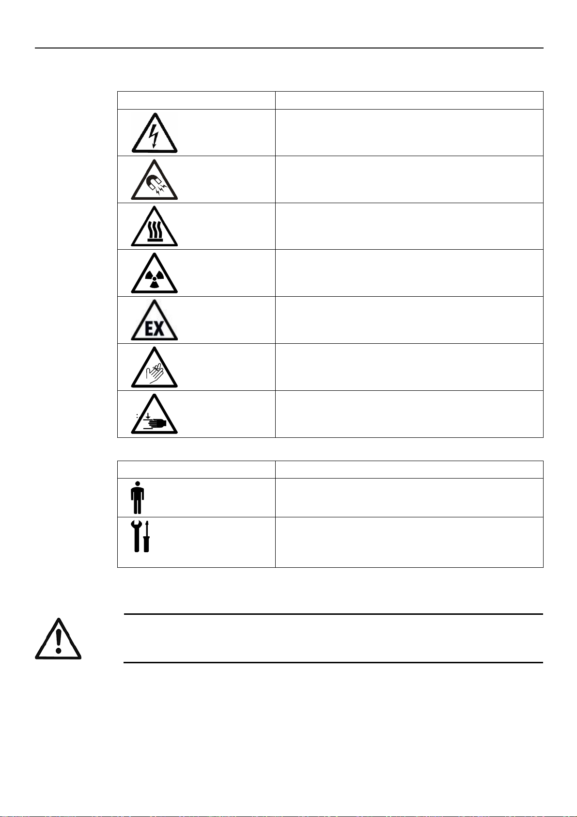
Symbol
Description
Electrical hazard
Magnetic hazard
Hot surface hazard
Ionizing radiation hazard
Potentially explosive atmosphere hazard
(ATEX EU Directive)
Cut and abrasion hazard
Crushing hazard (limbs)
Symbol
Description
User
Specific information for the users of the product.
Installer / Maintenance technician
Specific information for personnel responsible for the
installation of the product within the system (hydraulic
and/or electric system), and for maintenance operations.
WARNING:
This product must be used only by qualified users.
Special symbols
Some hazard categories have specific symbols, as shown in the following table:
Other symbols
1.2.2 User safety
Strictly comply with current health and safety regulations.
For the purposes of this manual, in addition to the provisions of any local regulations, qualified
personnel means any individuals who, due to their experience or training, are capable of
recognising any existing hazards and to avoiding dangers during the installation, the use and the
maintenance of the product.
6
Page 7
Inexperienced users
WARNING:
FOR THE EUROPEAN UNION
This appliance can be used by children aged from 8 years and above and persons with
reduced physical, sensory or mental capabilities or lack of experience and knowledge if they
have been given supervision or instruction concerning use of the appliance in a safe way and
understand the hazards involved.
Children shall not play with the appliance.
Cleaning and user maintenance shall not be made by children without supervision.
FOR OTHER COUNTRIES
This appliance is not intended for use by persons (including children) with reduced physical,
sensory or mental capabilities, or lack of experience and knowledge, unless they have been
given supervision or instruction concerning use of the appliance by a person responsible for
their safety.
Children should be supervised to ensure that they do not play with the appliance.
WARNING:
Always keep the work area clean.
Pay attention to the risks presented by gas and vapors in the work area.
Always bear in mind the risk of drowning, electrical accidents, and burn injuries.
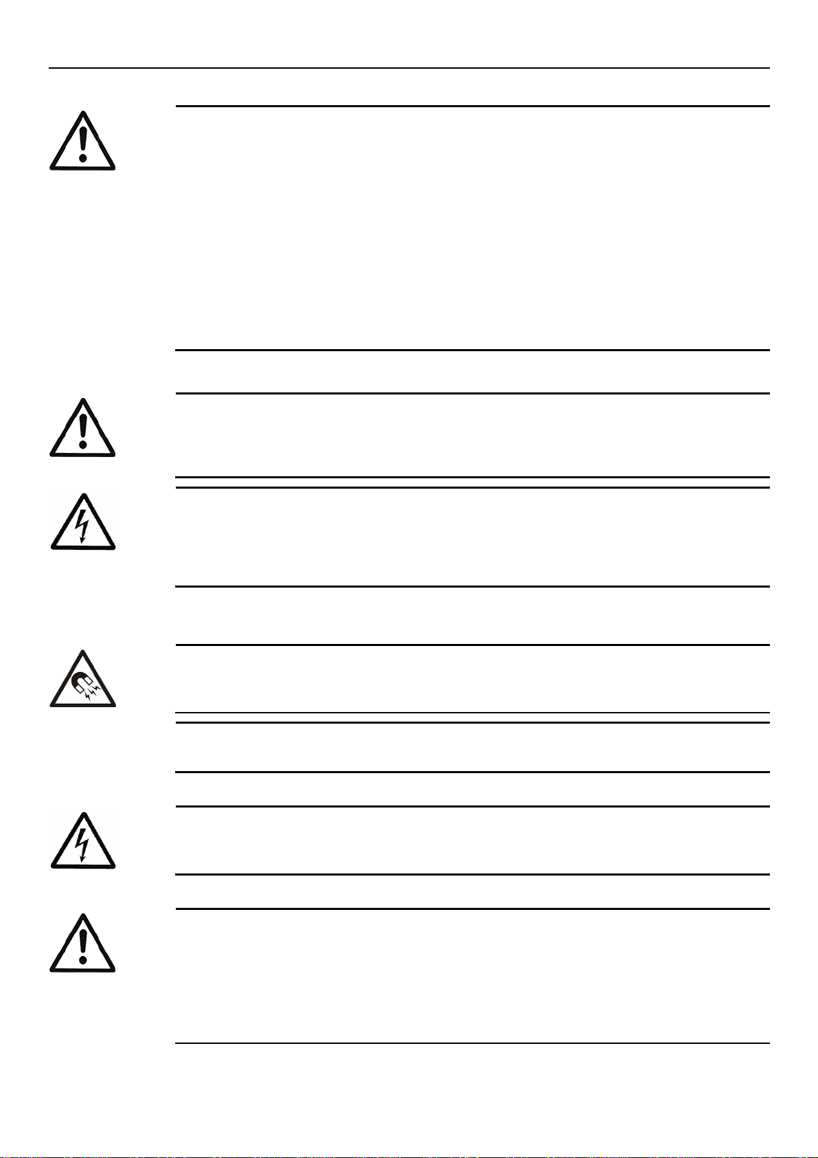
DANGER: Electrical hazard
Avoid all electric dangers; pay attention to the risk of electric shock or electric arcs
Unintended rotation of motors creates voltage and can charge the unit, resulting in death,
serious injury, or equipment damage. Ensure that motors are blocked to prevent unintended
rotation.
DANGER: Magnetic hazard
The magnetic field may be dangerous for anyone wearing peacemakers, or any other medical
devices sensitive to magnetic fields.
NOTE
The magnetic field may attract metal debris on the rotor surface, causing damage to the same.
DANGER: Electrical hazard
The connection to the electric power supply must be completed by an electrician possessing
the technical-professional requirements outlined in the current regulations
WARNING:
Install a suitable barrier around the working area, for example a guard rail
Make sure that all safety guards are in place and secure.
Make sure that you have a clear path of retreat.
Make sure that the product cannot roll or fall over and injure people or damage property.
Make sure that the lifting equipment is in good condition.
Use a lifting harness, a safety line, and a breathing device as required.
1.2.3 General safety rules
en – Original instructions
Magnetic fields
The removal or installation of the rotor in the motor casing generates a strong magnetic field.
Electrical connections
Precautions before work
7
Page 8
en – Original instructions
Allow all pump system components to cool before handling them
Make sure that the product has been thoroughly cleaned
Disconnect and lock out power before you service the pump.
Check the explosion risk before you weld or use electric hand tools.
WARNING:
Never work alone.
Always wear personal protective equipment
Always use suitable working tools
Always lift the product by its lifting device.
Stay clear of suspended loads.
Beware of the risk of a sudden start if the product is used with an automatic level control.
Beware of the starting jerk, which can be powerful.
Rinse the components in water after you disassemble the pump.
Do not exceed the maximum working pressure of the pump.
Do not open any vent or drain valve or remove any plugs while the system is pressurized.
Make sure that the pump is isolated from the system and that all pressure is released before
disassembling the pump, removing plugs, or disconnecting the piping
Never operate the pump without a properly installed coupling guard.
Condition
Action
Chemicals or hazardous fluids
in eyes
1. Hold your eyelids apart forcibly with your fingers.
2. Rinse the eyes with eyewash or running water for at least 15 min.
3. Seek medical attention.
Chemicals or hazardous fluids
on skin
1. Remove contaminated clothing.
2. Wash the skin with soap and water for at least 1 min.
3. Seek medical attention, if necessary.
WARNING: Ionizing radiation hazard
If the product has been exposed to ionizing radiations, implement the necessary safety measures
for the protection of people. If the product needs to be despatched, inform the carrier and the
recipient accordingly, so that appropriate safety measures can be put in place.
Precautions during work
In case of contact with chemical substances or dangerous liquids
Follow these procedures for chemicals or hazardous fluids that have come into contact with your
eyes or your skin:
1.2.4 Protection of the environment
Disposal of packaging and product
Comply with the current regulations on sorted waste disposal.
1.2.5 Sites exposed to ionizing radiations
1.3 Spare parts
1.4 Product warranty
8
When contacting Xylem or the Authorised Distributor to request technical information or spare
parts, always indicate the product type and code.
For information on the warranty refer to the documentation of the sale contract.
Page 9
en – Original instructions
CAUTION: Cut and abrasion hazard
Always wear personal protective equipment.
WARNING: Crushing hazard (limbs)
The product and its components may be heavy: risk of crushing
Always wear personal protective equipment
Manual handling of the product and its components must be in compliance with the current
regulations on "manual load handling", to avoid unfavourable ergonomic conditions causing
risks of back-spine injury.
Use cranes, ropes, lifting straps, hooks and clasps that comply with current regulations and
that are suitable for the specific use
Make sure that the harnessing does not damage the unit
During the lifting operations, always avoid sudden movements that could compromise the
stability of the load
During handling, make sure to avoid injury to people and animals, and/or damage to property.
2 Transportation and Storage
Packaging inspection
1. Check that quantity, descriptions and product codes match the order.
2. Check the packaging for any damage or missing components.
3. In case of immediately detectable damage or missing parts:
Accept the goods with reserve, indicating any findings on the transport document, or
Reject the goods, indicating the reason on the transport document.
In both cases, promptly contact Xylem or the Authorised Distributor from whom the product was
purchased.
Unpacking and inspection of the unit
1. Remove packing materials from the product.
2. Release the product by removing the screws and/or cutting the straps, if fitted.
3. Check the product for integrity and to make sure that there are no missing components.
4. In case of damage or missing components, promptly contact Xylem or the Authorised
Distributor.
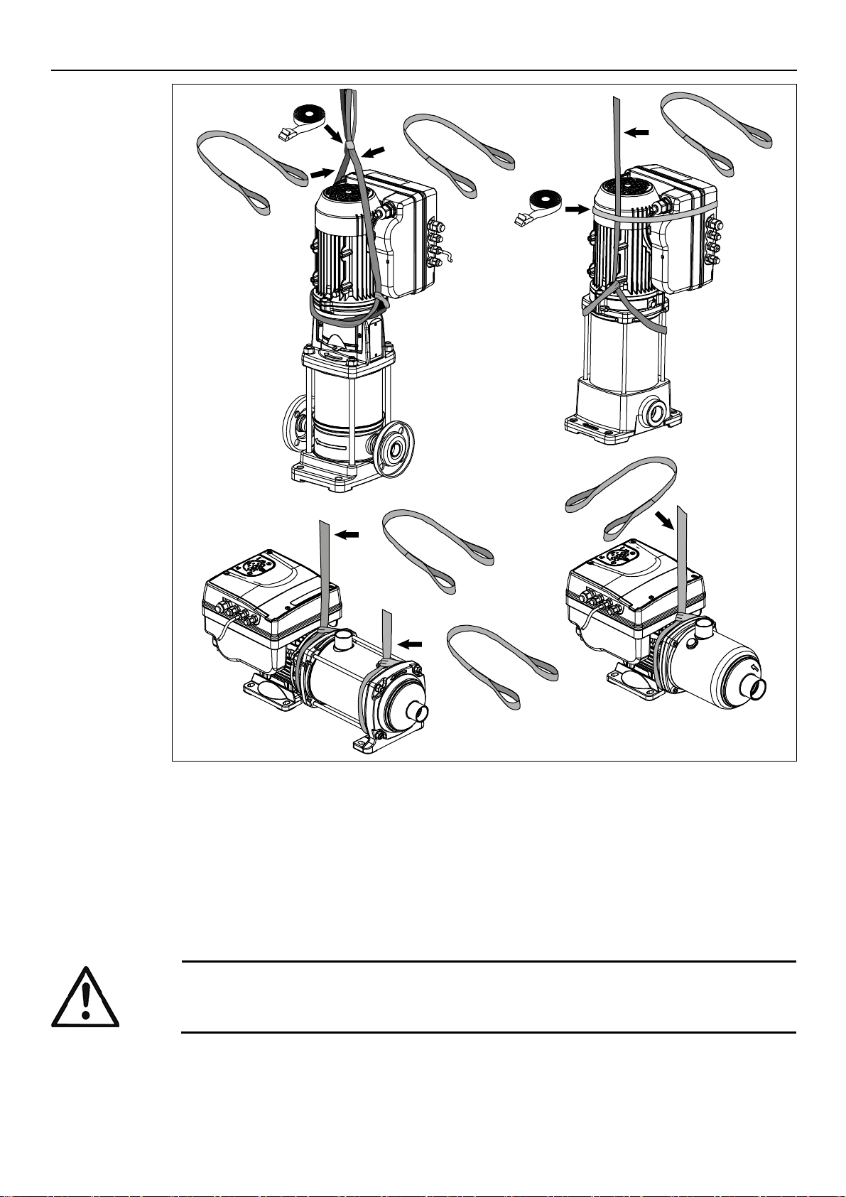
2.1 Unit handling
The unit must be harnessed and lifted as shown in Figure 1.
9
Page 10
en – Original instructions
Figure 1: Lifting
NOTICE:
Do not place heavy loads on top of the product
Protect the product from collisions.
1 x
1 x
1 x
1 x
e-SVE
VME
e-HME
1 x
1 x
1 x
1 x
ESM_M0002_C_sc
2.2 Storage
The product must be stored:
In a covered and dry place
Away from heat sources
Protected from dirt
Protected from vibrations
At an ambient temperature between -25°C and +65°C (-13°F and 149°F), and relative
humidity between 5% and 95%.
10
Page 11
3 Technical Description
only
+
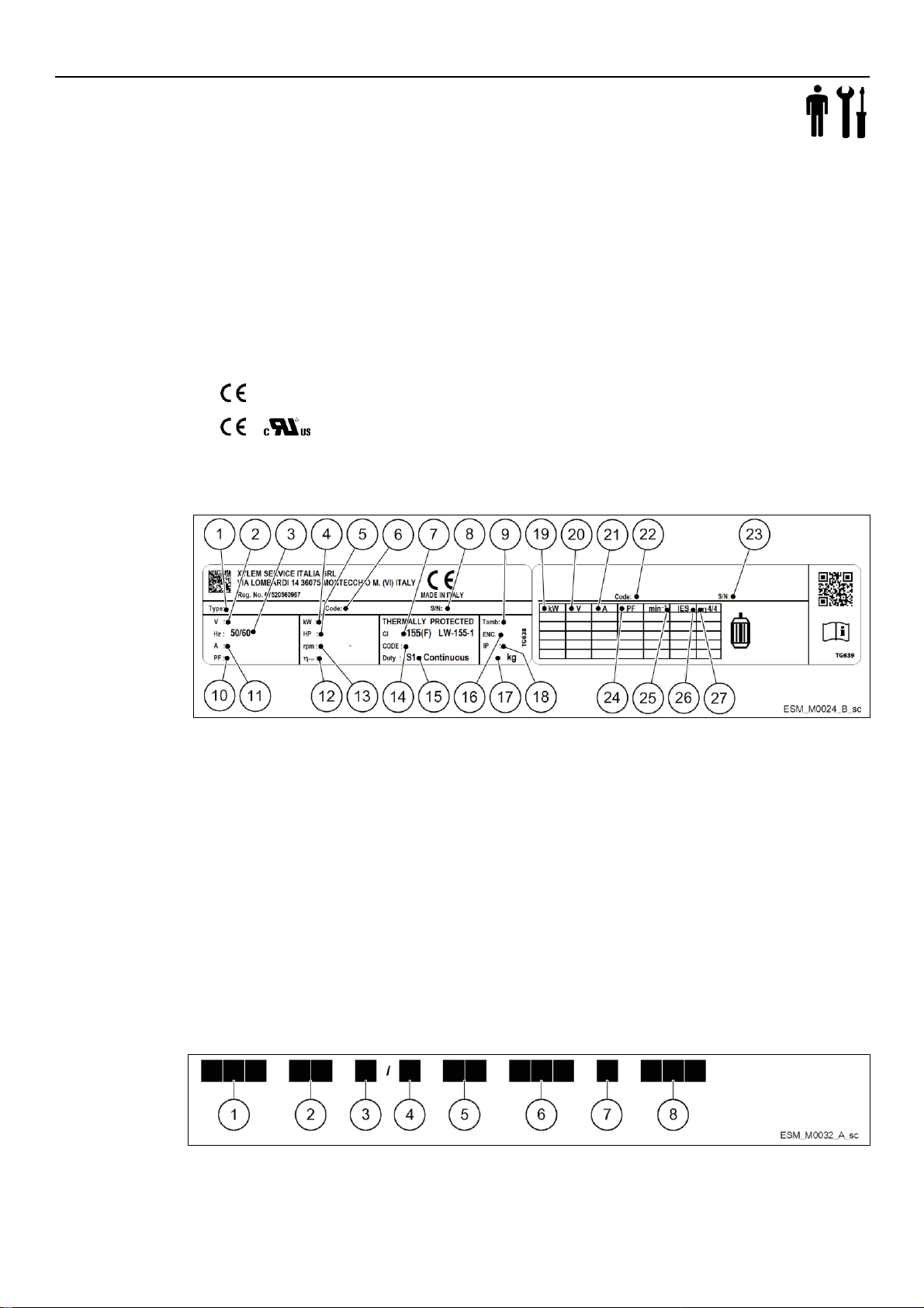
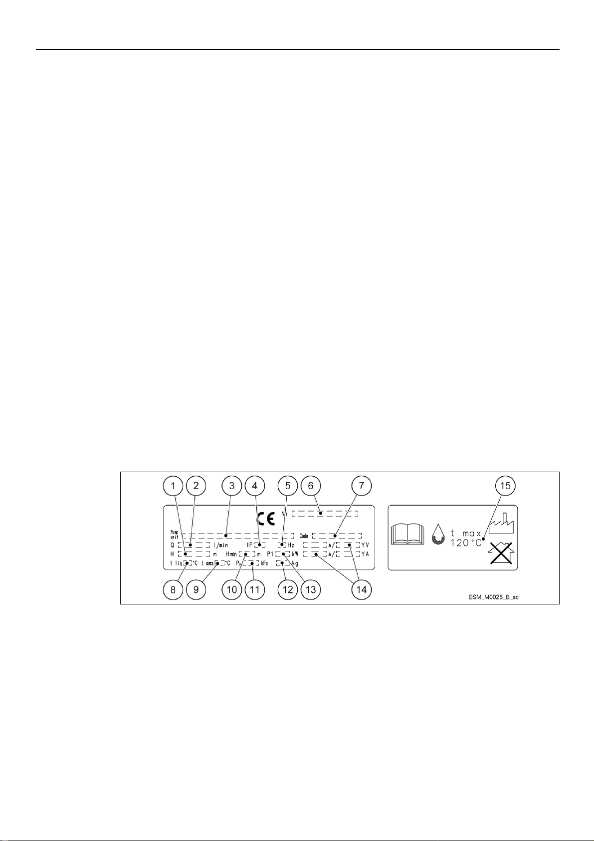
Figure 2: Motor data plate
1. Type definition code
2. Rated voltage
3. Rated frequency
4. Rated power [kW]
5. Rated power [HP]
6. Part number
7. Insulation class
8. Serial number
9. Maximum ambient temperature
10. Power factor
11. Rated current
12. Motor drive efficiency
13. Full power speed range
14. Code letter for locked rotor
15. Duty type
16. Enclosure type (NEMA)
17. Weight
18. Protection class
19. Shaft power
20. Voltage
21. Current
22. Part number
23. Serial number
24. Power factor
25. Speed
26. Power drive system efficiency class (according to EN
50598-2)
27. Full load efficiency
Figure 3: Motor type definition code
3.1 Designation
Variable speed pump unit, vertical/horizontal, multi-stage, non self-priming.
3.2 Data plates
The data plate is a label showing:
The main product details
The identification code
Approval and certifications
For the approvals see the motor data plate:
3.2.1 Motor
Motor data plate
en – Original instructions
Motor type definition code
11
Page 12
en – Original instructions
1. Series
ESM
2. Motor frame dimension
90R: Oversized Flange
80: Standard Flange
3. Shaft extension
□□: Standard shaft extension
S8: Custom Shaft extension
4. Power supply
1: single phase power supply
3: three phase power supply
5. Shaft power•10 [kW]
03: 0.37kW (0.50HP)
05: 0.55 kW (0.75 HP)
07: 0.75 kW (1.00 HP)
11: 1.10 kW (1.50 HP)
15: 1.50 kW (2.00 HP)
22: 2.20 kW (3.00 HP)
6. Motor frame arrangement
SVE: Flange with tapped holes and shaft w/o keyseat
B14: Flange with tapped holes
B5: Flange with free holes
HMHA:Suitable for 1-5 e-HME monolithic pumps
HMHB: Suitable for 1-5 e-HME pumps w/sleeve
HMVB:Suitable for 1-5 VM pumps
HMHC:Suitable for 10-22 e-HME pumps
HMVC:Suitable for 10-22 VM pumps
LNEE: Suitable for In-Line pumps
56J: Compliant to NEMA 56 Jet standard
56C: Compliant to NEMA 56C standard
7. Reference market
□□: Standard
EU:EMEA
US: North America
8. Voltage
208-240 : 208-240VAC 50/60Hz
380-460 : 380-460VAC 50/60Hz
230/400: 208-240/380-460VAC 50/60Hz
Figure 4: e-HME/VME data plate
1. Head range
2. Flow range
3. Pump/electric pump unit type definition code
4. Protection class
5. Frequency
6. Serial number (date+progressive number)
7. Electric pump unit/pump part number
8. Maximum operating liquid temperature (uses as EN
60335-2-41)
9. Maximum operating ambient temperature
10. Minimum head (EN 60335-2-41)
11. Maximum operating pressure
12. Electric pump unit weight
13. Electric pump unit absorbed power
14. Electrical data
15. Maximum operating liquid temperature (uses other
than as EN 60335-2-41)
3.2.2 Pump
e-HME/VME data plate
12
Page 13
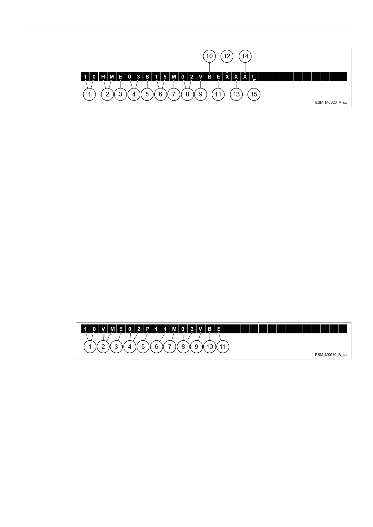
e-HME type definition code
Figure 5: e-HME type definition code
1. Rated flow rate
[10] = m3/h
2. Series name
[HM]
3. Motor operation
[E] = e-SM
4. Number of impeller
[03] = 3 impellers
5. Material pump
[S] = Stainless steel (AISI 304)
6. Motor power
kW x 10
7. Phase
[M] = Single-phase
[T] = Three-phase
8. Power Supply Voltage
e-SM Power supply
02 = 1x208-240 V
04 = 3x380-460 V
05 = 3x208-240/380-460 V
9. Rotating part
[Q] = Silicon Carbide (Q1)
[V] = Aluminium oxide (Ceramic)
10. Stationary part
[Q] = Silicon Carbide (Q1)
[B] = Carbon resin impregnated
11. Elastomers
[E] = EPDM
[V] = FPM
[K] = FFPM (Kairez®)
12. General characteristics
Null = None
Z = other
13. General characteristics
Null = None
14. Connections
Null = Threaded
15.
Null or letter assigned by the manufacturer
Figure 6: VME type definition code
1. Rated flow rate
[10] = m3/h
2. Series name
[VM]
3. Motor operation
[E] = e-SM
4. Number of impeller
[02] = 2 impellers
5. Material pump
[P] = Stainless steel AISI 304 with Noryl™ impellers
6. Motor power
kW x 10
7. Phase
[M] = Single-phase electric pump
[T] = Three-phase electric pump
8. Power Supply Voltage
[2] = 1x208-240 V
[4] = 3x380-460 V
[5] = 3x208-240/380-460 V
9. Rotating part
[V] = Aluminium oxide (Ceramic)
10. Stationary parts
Carbon resin impregnated
11. Elastomers
[E] = EPDM
en – Original instructions
VME type definition code
13
Page 14
en – Original instructions
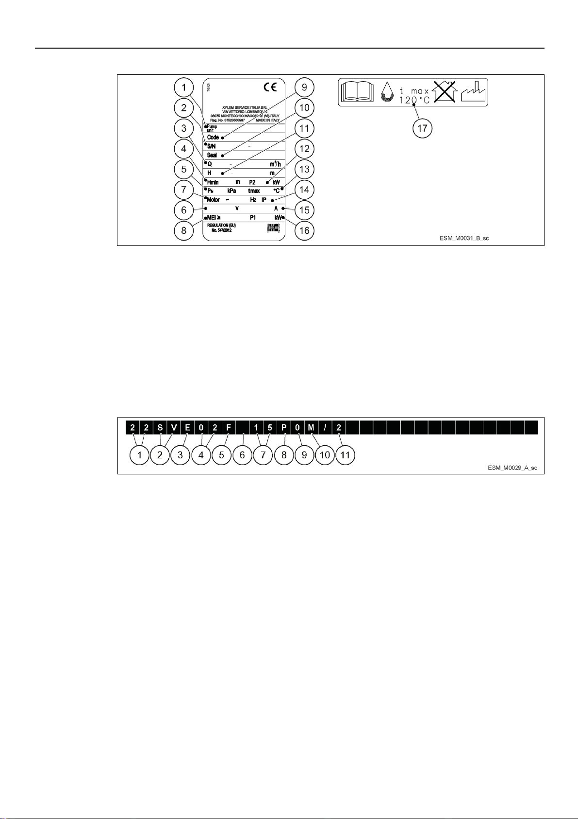
Figure 7: e-SVE data plate
1. Pump/electric pump unit type
2. Serial number (date+progressive number)
3. Flow range
4. Minimum head (EN 60335-2-41)
5. Maximum operating pressure
6. Rated voltage range
7. Frequency
8. Minimum efficiency index
9. Electric pump unit/ pump part number
10. Mechanical seal material identification code
11. Head range
12. Motor power
13. Maximum operating liquid temperature (uses as EN
60335-2-41)
14. Protection class
15. Current
16. Electropump unit absorbed power
17. Maximum operating liquid temperature (uses other
than as EN 60335-2-41)
Figure 8: e-SVE type definition code
1. Rated flow rate
[22] = m3/h
2. Series name
[SV]
3. Motor operation
[E] = e-SM
4. Number of impeller
[02] = 2 impellers
5. Material pump
[F] = Stainless steel AISI 304, round flanges (PN 25)
[T] = Stainless steel AISI 304, oval flanges (PN 16)
[R] = Stainless steel AISI 304, discharge port above suction, round flanges (PN 25)
[N] = Stainless steel AISI 316, round flanges (PN 25)
6. Version
Null = standard version
7. Motor power
kW x 10
8. Number of poles
[P] = e-SM
9. Frequency
[0] = e-SM
10. Phase
Null = pump
[M] = Single-phase electric pump
[T] = Three-phase electric pump
11. Power Supply Voltage
[2] = 1x208-240 V
[4] = 3x380-460 V
[5] = 3x208-240/380-460 V
e-SVE data plate
e-SVE type definition code
14
Page 15
3.3 Design and layout
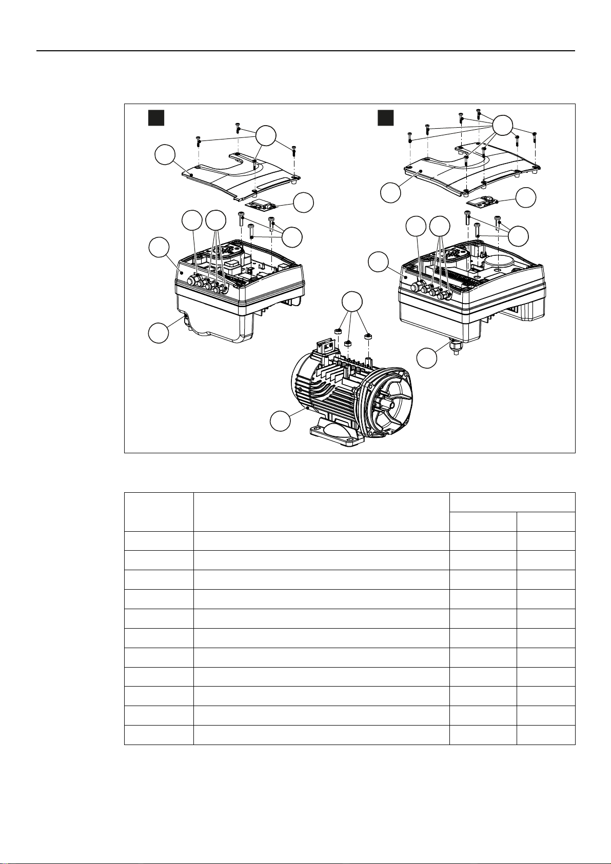
Figure 9: Main components - Single-phase and three-phase models
Table 1: Description of components
Position
number
Description
Tightening torque ±15%
[Nm]
[in•lbs]
1
Screw
1.4
12.4
2
Terminal Box Cover
-
-
3
Optional module with strip
-
-
4
M12 I/O cable gland
2.0
17.7
5
M20 cable gland for power supply cables
2.7
23.9
6
M16 I/O cable gland
2.8
24.8
7
Drive (single-phase model)
-
-
8
Motor - -
9
Screw
6.0
53.1
10
Drive (three-phase model)
-
-
11
Spacer - -
5
2
3
6 4
5
9
1
7
3
9
1
6 4
10
2
1~ 3~
ESM_T0022_A_sc
8
ESM_M0005_B_sc
11
The unit can be fitted with the features the application requires
en – Original instructions
15
Page 16
en – Original instructions
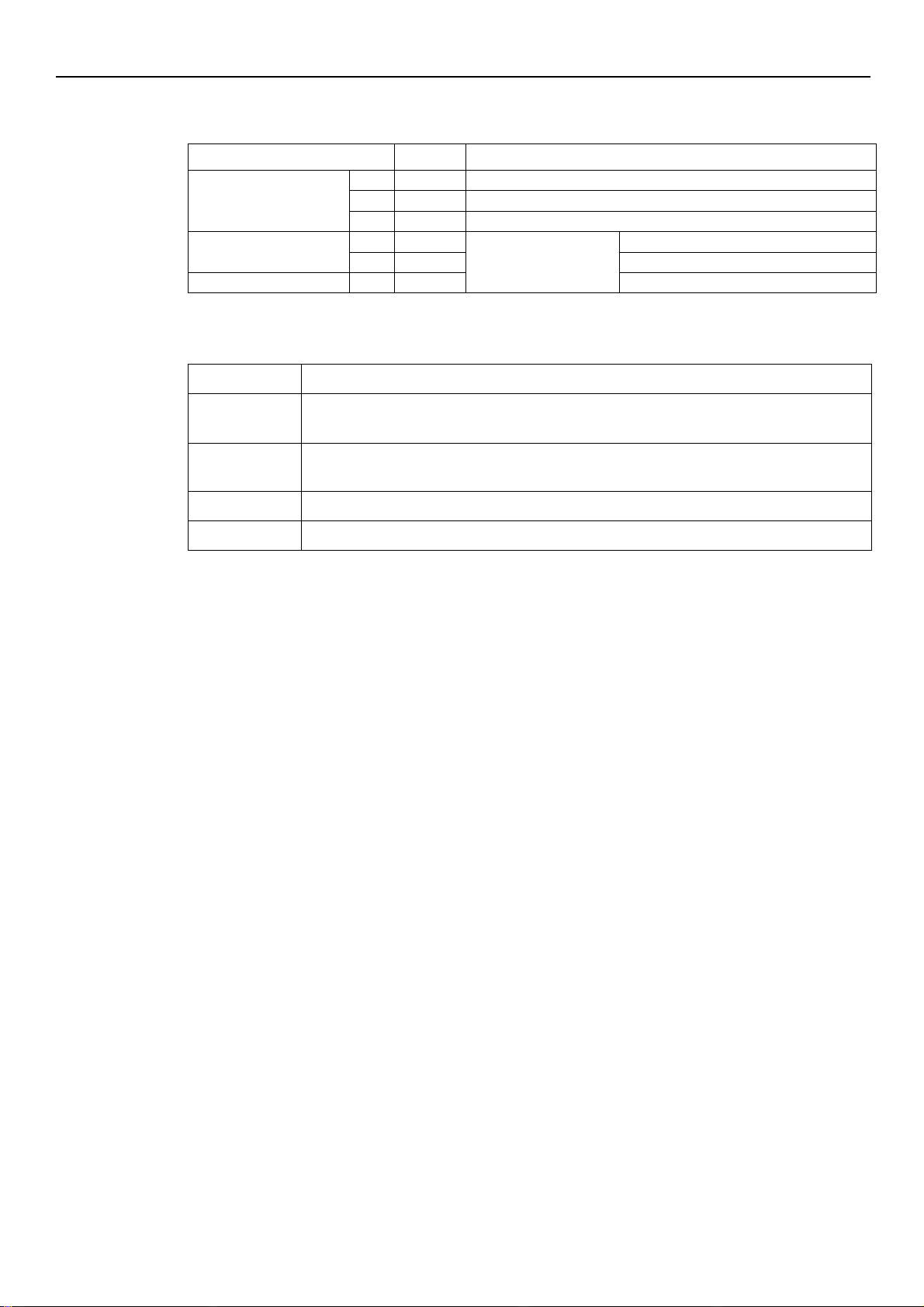
Table 2: Included components
Component
Quantity
Notes
Plug for Cable Gland
M12 3
M16 1
M20 1
Cable gland and lock nut
M12
3
Cable Outer Diameter:
3.7 to 7.0 mm (0.145-0.275 in)
M16 1 4.5 to 10.0 mm (0.177-0.394 in)
Cable Gland
M20 1 7.0 to 13.0 mm (0.275-0.512 in)
Table 3: Optional components
Component
Description
Sensors
The following sensors can be used with the unit:
Level-sensor
RS485 Module
For the connection of a multi-pump system to a supervision system, via cable (Modb us or BACnet
MS/TP protocol)
Wireless Module
To connect and interact wireless with e-SM Drive
Adaptor
M20 Metric to 1/2" NPT Adapter (item is always supplied for US market)
Pre-assembled ex factory components
Optional components
3.4 Intended use
The product can be used to pump:
Cold water
Hot water
Refer to the standard Installation, Operation and Maintenance Manual for pump design
specification.
The variable speed pump units are made for the following applications:
Pressure, level, and flow regulation (open loop systems)
Single or multi pump irrigation systems.
3.4.1 Application alternatives
Actuator (constant speed)
The unit operates as an actuator according to speed set point; this is done through user
interface, the corresponding analog input or the communication bus.
Controller (constant pressure)
This mode is set as the default operating mode, and is used for single pump operating units.
Cascade serial / Cascade synchronous
The units are connected via the RS485 interface and communicate via the provided protocol.
The combination of the different units which are used in a multi-pump system depends on the
system requirements.
It is possible to run all pumps in cascade serial mode and cascade synchronous mode as well. If
one unit fails, then each pump of the system can become the lead pump and can take control.
3.5 Improper use
The product must not be used for closed loop systems.
16
Page 17
en – Original instructions
DANGER: Potentially explosive atmosphere hazard
The operation of the unit in environments with potentially explosive atmospheres or with
combustible dusts (e.g.: wood dust, flour, sugars and grains) is strictly forbidden.
WARNING:
Always wear personal protective equipment
Always use suitable working tools
When selecting the place of installation and connecting the unit to the hydraulic and electric
power supplies, strictly comply with current regulations.
Ensure that the input protection rating of the unit (IP 55, NEMA Type 1) is suitable for the
installation environment.
CAUTION:
Input protection: to ensure the IP55 (NEMA type 1) protection index make sure that the unit is
closed correctly.
Before opening the terminal box cover, make sure that there is no water in the unit
Make sure that all unused cable glands and cable holes are correctly sealed
Make sure that the plastic cover is correctly closed
Do not leave the terminal box without cover: risk of damage due to contamination.
4 Installation
4.1 Mechanical installation
4.1.1 Installation area
4.1.2 Unit installation
See the Quick Startup Guide instructions (code 001080128)
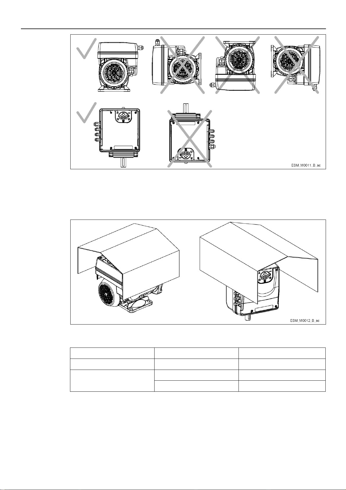
Position the unit as shown in Figure 10
Install the unit according to the systems liquid flow.
The arrows on the pump body indicate the flow and the rotation direction
The standard rotation direction is clockwise (looking at the fan cover)
Always install a backflow-prevention device on the suction side.
Always install the pressure sensor on the delivery side, after the check valve.
17
Page 18
en – Original instructions
Figure 10: Permitted positions
Figure 11: Outdoor installation
Area
e-SM Drive model
Free Distance
Above the unit
103..105..107..111..115
> 260mm (10.2 in)
Center-distance between units (to
ensure space for cabling)
103..105..107..111..115
> 260mm (10.2 in)
303..305..307..311..315..322
≥ 300mm (11.8 in)
4.1.3 Outdoor unit installation
Minimum spacing
In case of outdoor unit installation, ensure appropriate cover (see example in Figure 11).
The size of the cover must be such that the motor is not exposed to snow, rain or direct sunlight;
comply with the guidelines of Par. 9, Table 16.
18
Page 19
4.2 Hydraulic installation
NOTICE:
If the system is directly connected to the water network, install a minimum pressure switch on the
suction side.
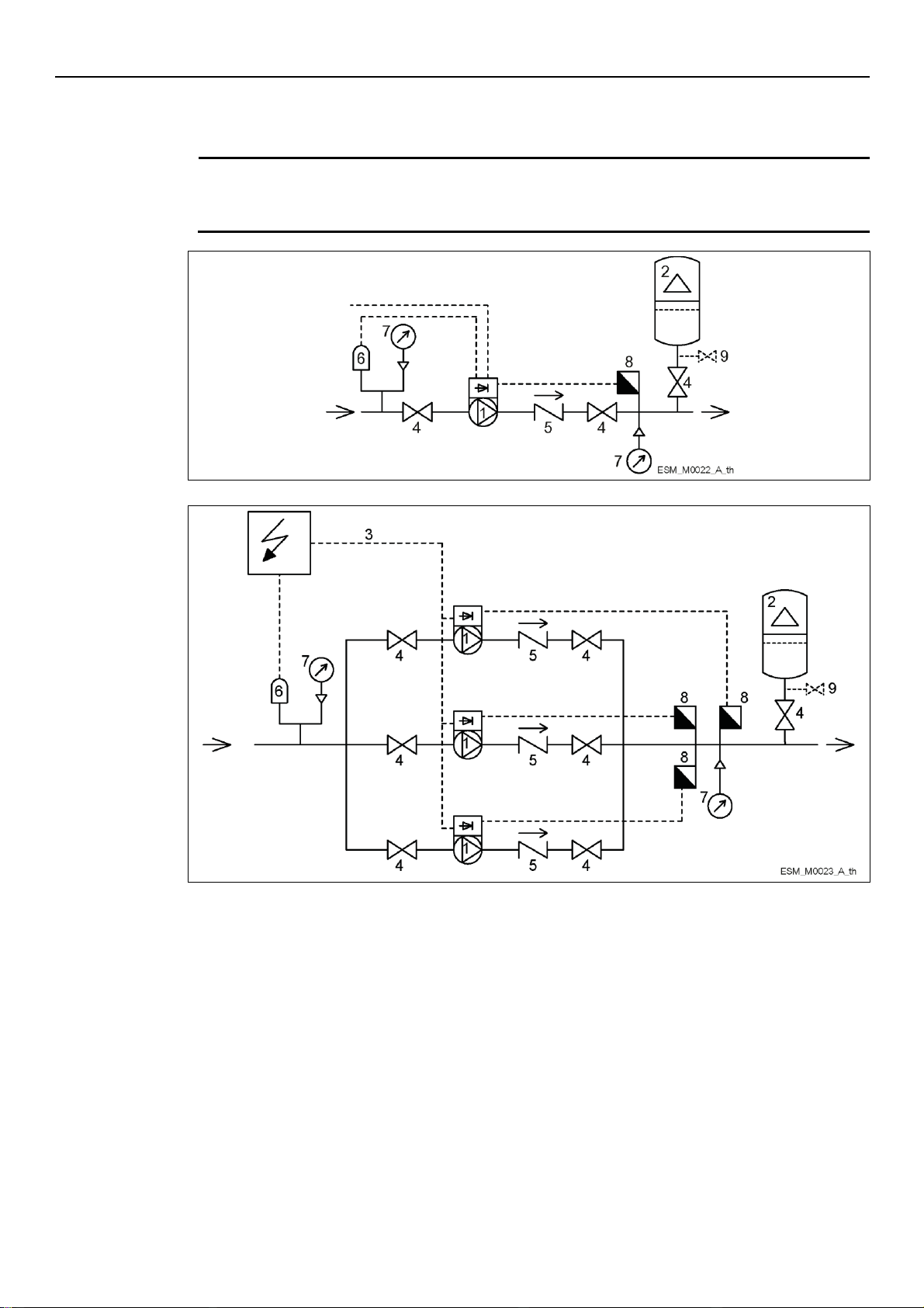
Figure 12: Single-pump system
Figure 13: Multi-pump system
1. Pump with e-SM Motor Drive
2. Diaphragm pressure tank
3. Distribution panel
4. On-off valve
5. Non-return valve
6. Low water control
7. Pressure gauge
8. Pressure sensor
9. Drain tap
Figure 12 and 13 show a single pump system and a multi-pump system respectively.
en – Original instructions
Pressure tank
On the pump delivery side there is a membrane expansion vessel, which gives the possibility of
maintaining the pressure inside the piping when the system is not being used. The unit stops the
pump from continuing to run at zero demand and reduce the size of the tank that is required for
supply purposes.
Select a vessel suitable for the system pressure, and pre-load it in accordance with the values
indicated in the Quick Startup Guide (code 001080128).
19
Page 20
en – Original instructions
DANGER: Electrical hazard
The connection to the electric power supply must be completed by an electrician possessing the
technical-professional requirements outlined in the current regulations.
NOTICE:
The control panel must match the ratings of the electric pump. Inappropriate combinations do not
guarantee the protection of the unit.
DANGER: Electrical hazard
Before starting work on the unit, make sure that the unit and the control panel are isolated from
the power supply and cannot be energized.
DANGER: Electrical hazard
Always connect the external protection conductor to the ground terminal before attempting to
make any other electrical connections
Connect all the electric accessories of the pump and the motor to the ground, making sure that
the connections are completed correctly
Check that the protection conductor (ground) is longer than the phase conductors; in case of
accidental disconnection of the power supply conductor, the protection conductor (ground)
must be the last one to detach itself from the terminal.
4.3 Electrical Installation
4.3.1 Electrical requirements
Local directives prevail on the specific requirements indicated below.
Electrical connection checklist
Check that the following requirements are met:
The electrical leads are protected from high temperature, vibrations, and collisions.
The current type and voltage of mains connection must correspond to the specifications on
the data plate on the pump.
The power supply line is provided with:
- A high-sensitivity differential switch (30 mA) [residual current device RCD] suitable for
earth fault currents with DC or pulsating DC content (a Type B RCD is suggested).
- A mains isolator switch with a contact gap of at least 3 mm.
The electrical control panel checklist
Check that the following requirements are met:
The control panel must protect the pump against short-circuit. A time lag fuse or a circuit
breaker (Type C model is suggested) can be used to protect the pump.
The pump has built in overload and thermal protection, no additional overload protection is
required.
Grounding (earthing)
Use a cable with several strands to reduce electric noise.
20
Page 21
4.3.2 Wire types and ratings
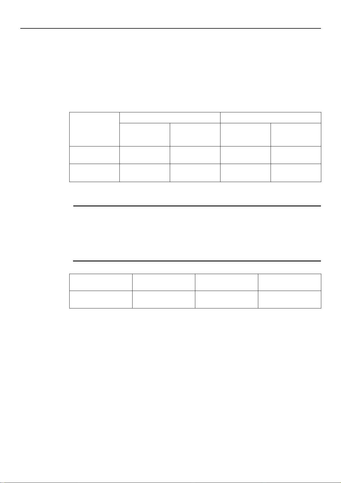
Table 4: Electric connection cables
e-SM Drive models
Power supply input cable + PE
Tightening torque
Wire numbers
x Max. copper
section
Wire numbers
x Max. AWG
Mains and motor
cable terminals
Earth Conductor
103, 105, 107, 111,
115
3 x 1.5 mm
2
3 x 0.0023 sq.in
3 x 15 AWG
Spring connectors
Spring connectors
303, 305, 307, 311,
315, 322
4 x 1.5 mm
2
4 x 0.0023 sq.in
4 x 15 AWG
0.8 Nm
7.1 lb-in
3 Nm
26.6 lb-in
NOTICE:
Install the control cables separate from the power supply cables and the fault signal relay
cable
If the control cables are installed in parallel with the power supply cable or the fault signal
relay, the distance between the cables must exceed 200 mm
Do not intersect the power supply cables; should this be necessary, a 90°intersection angle is
permitted.
Table 5: Recommended control cables
e-SM Drive control cables
Wires number
x Max. copper Section
AWG
Tightening torque
All I/O conductors
0.75-1.5 mm2
0.00012-0.0023 sq.in
18-16 AWG
0.6 Nm
5.4 lb-in
All cables must comply with local and national standards in terms of section and ambient
temperature
Use cables with minimum heat resistance +70°C (158°F); to ensure compliance with UL
(Underwriters Laboratories) regulations, all power supply connections must be completed
using the following types of copper cables with minimum resistance +75°C: THW, THWN
Cables must never enter into contact with the motor body, the pump and the piping.
The wires connected to the power supply terminals and the fault signal relay (NO, C) must be
separated from the others by means of reinforced insulation.
Control cables
en – Original instructions
External volt free contacts must be suitable for switching < 10 VDC.
21
Page 22
en – Original instructions
WARNING: Electrical hazard
Contact with electric components may cause death, even after the unit has been switched off.
Before any interventions on the unit, the network voltage and any other input voltages must be
disconnected for the minimum time indicated in Table 9.
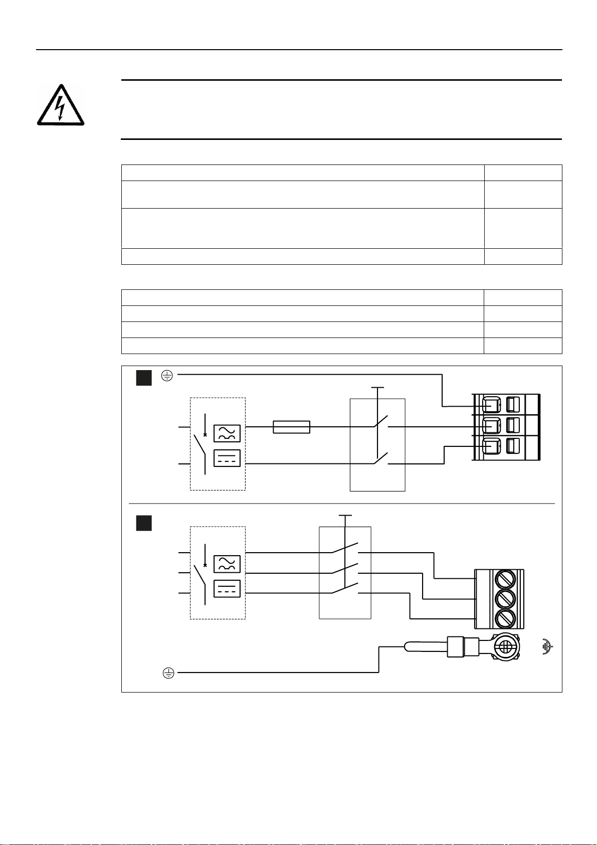
Table 6: Power supply wiring procedure
Reference
1. Open the terminal box cover (2) by removing the screws (1).
2. Insert the power cable in the M20 cable gland (5)
Fig. 9
3. Connect the cable according to the wiring diagram.
4. Connect the earth conductor (mass), making sure that it is longer than the phase conductors.
5. Connect the phase leads.
Fig. 14
6. Close the cover (2) and tighten the screws (1).
Fig. 9
Table 7: I/O wiring procedure
Reference
1. Open the terminal box cover (2) by removing the screws (1).
Fig. 9
2. Connect the cable according to the wiring diagram.
Fig. 15
3. Close the cover (2) and tighten the screws (1).
Fig. 9
Figure 14: Wiring diagram
ESM_M0007_B_sc
N
1
2
3
10 A
L
ESM_T0008_D_sc
1
L1
208÷240
380÷460
L2
L3
L1
L2
L3
4
3
2
1~
3~
4.3.3 Power supply connection
22
Page 23
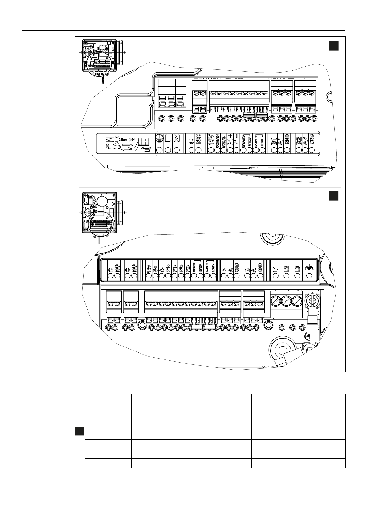
Figure 15: Connection label
Table 8: I/O terminals
Item
Terminals
Ref.
Description
Notes
Fault Signal
C
4
COM - error status relay
NO
5
NO - error status relay
Auxiliary Voltage
Supply
15V
6
Auxiliary voltage supply +15 VDC
15VDC, Ʃ max. 100 mA
Analog input
0-10V
P2IN/S+
7
Actuator mode 0-10 V input
0-10 VDC
P2C/S-
8
GND for 0-10 V input
GND, electronic ground (for S+)
External Pressure
P1+
9
Power supply external sensor +15
15VDC, Ʃ max. 100 mA
ESM_M0009_E_sc
ESM_T0023_A_sc
1 2 3 4 5 6 87 9 10 11 12 13 14 15 16 17 18 19 20
25 24 23 22 21 20 19 18 17 16 15 14 13 12 11 10 9 8 7 6 5 4 3 2 1
1~
3~
1~
en – Original instructions
23
Page 24
en – Original instructions
sensor [also
Differential]
VDC
P1-
10
External sensor 4-20 mA input
4-20 mA
External Start/Stop
START
11
External ON/OFF input reference
Default short circuited Pump is enabled
to RUN
STOP
12
External ON/OFF input
External Lack of
Water
LOW+
13
Low water input
Default short circuited
Lack of water detection: enabled
LOW-
14
Low water reference
Communication
bus
B1
15
RS485 port 1: RS485-1N B (-)
ACT, HCS control mode: RS 485 port1 for
external communication
MSE, MSY control mode: RS 485 port 1
for multi-pump systems
A1
16
RS485 port 1: RS485-1P A (+)
GND
17
Electronic GND
Communication
bus
B2
18
RS485 port 2: RS485 port 2: RS4852N B (-) active only with optional
module
RS 485 port2 for external
communication
A2
19
RS485 port 2: RS485 port 2: RS4852P A (+) active only with optional
module
GND
20
Electronic GND
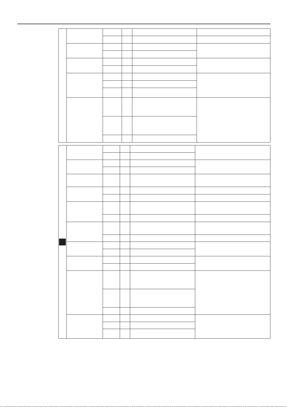
Fault signal
C
25
COM - error status relay
In case of power cables: use the M20
cable gland
NO
24
NO - error status relay
Motor running
signal
C
23
Common contact
In case of power cables: use the M20
cable gland
NO
22
Normally open contact
Auxiliary Voltage
Supply
15V
21
Auxiliary voltage supply +15 VDC
15VDC, Ʃ max. 100 mA
Analog input
0-10V
S+
20
Actuator mode 0-10 V input
0-10 VDC
S-
19
GND for 0-10 V input
GND, electronic ground (for S+)
External Pressure
sensor [also
Differential]
P1+
18
Power supply external sensor +15
VDC
15VDC, Ʃ max. 100 mA
P1-
17
External sensor 4-20 mA input
4-20 mA
External pressure
sensor
P2+
16
Power supply external sensor +15
VDC
15VDC, Ʃ max. 100 mA
P2-
15
Sensor 4-20 mA input
4-20 mA
External Start/Stop
Start
14
External ON/OFF input
Default short circuited Pump is enabled
to RUN
Stop
13
External ON/OFF input reference
External Lack of
Water
LoW+
12
Low water input
Default short circuited Lack of water
detection: enabled
LoW-
11
Low water reference
Communication
Bus
B2
10
RS485 port 2: RS485 port 2: RS4852N B (-) active only with optional
module
RS 485 port2 for external communication
A2
9
RS485 port 2: RS485 port 2: RS4852P A (+) active only with optional
module
GND
8
Electronic GND
Communication
Bus
B1
7
RS485 port 1: RS485-1N B (-)
ACT, HCS control mode: RS 485 port 1 for
external communication
Control mode MSE, MSY: RS 485 port 1
for multi-pump systems
A1 6 RS485 port 1: RS485-1P A (+)
GND 5 Electronic GND
3~
24
Page 25
en – Original instructions
WARNING: Electrical hazard
Contact with electric components may cause death, even after the unit has been switched off.
Before any interventions on the unit, the network voltage and any other input voltages must be
disconnected for the minimum time indicated in Table 9.
Table 9: Wait times
e-SM Drive model
Minimum waiting time (min)
103, 105, 107, 111, 115
4
303, 305, 307, 311, 315, 322
5
WARNING: Electrical hazard
Frequency converters contain DC-link capacitors that can remain charged even when the
frequency converter is not powered.
To avoid electrical hazards:
Disconnect the AC power supply
Disconnect all types of permanent magnet motors
Disconnect all DC-link remote power supplies, including the battery backups, the
Uninterrupted Power Supply units and the DC-link connections to other frequency converters
Wait for the capacitors to discharge completely before carrying out any maintenance or
repairs; see Table 9 for the waiting times
5 Operation
In case of co-existance of two or more of the following conditions:
high ambient temperature
high water temperature
duty points insisting on unit maximum power
persisting undervoltage of mains,
may jeopardise the life of the unit, and/or derating may occur: for further information contact
Xylem or the Authorised Distributor.
5.1 Wait times
25
Page 26
en – Original instructions
NOTICE:
Carefully read and follow the following instructions before starting the programming activities,
to avoid wrong settings that may cause malfunctioning
All modifications must be done by qualified technicians.
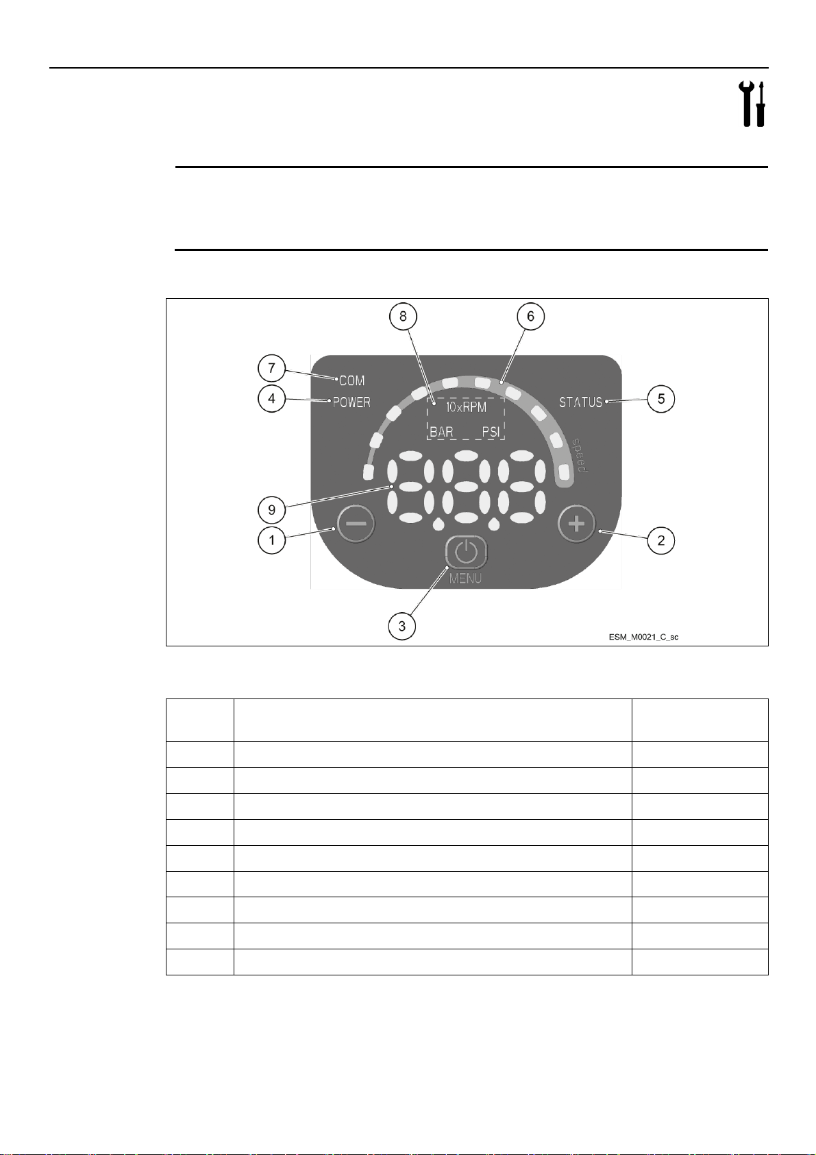
Figure 16: Control panel
Table 10: Description of the control panel
Position
number
Description
Para.
1
Decrease button
6.2
2
Increase button
6.2 3 START/STOP and menu access button
6.2
4
POWER LED
6.3.1
5
Status LED
6.3.2
6
Speed LED bar
6.3.3
7
Communication LED
6.3.4
8
Unit of measure LEDs
6.3.5
9
Display
6.4
6 Programming
Precautions
6.1 Control panel
26
Page 27
6.2 Description of the buttons
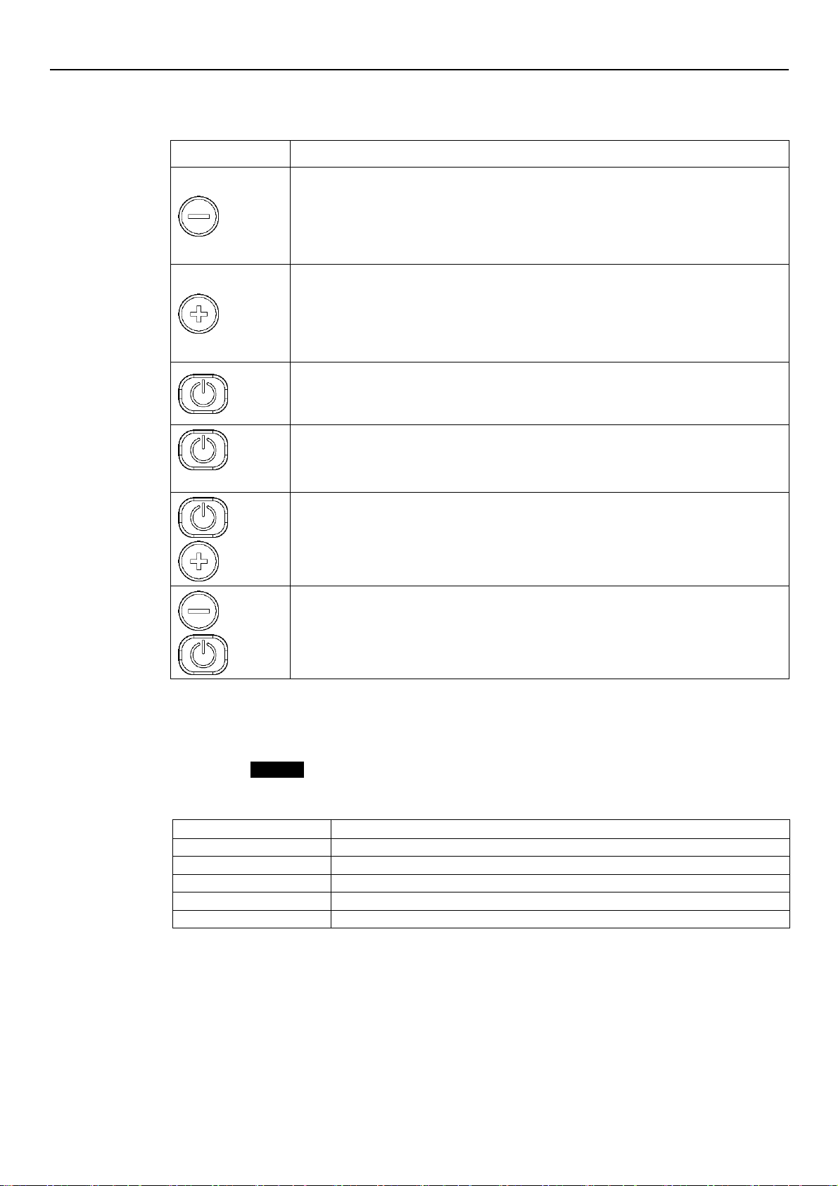
Table 11: Functions of push buttons
Push button
Function
Main view (see Par. 6.4.1): decreases the required value for the selected control mode
Parameter menu (see Par. 6.4.2): decreases the displayed parameter index
Parameter view / editing (see Par. 6.4.2): decreases the value of the displayed parameter
Zero pressure auto-calibration (see Par. 6.5, P44): automatic calibration of the pressure
sensor.
Main view (see Par. 6.4.1): increases the required value for the selected control mode
Parameter menu (see Par. 6.4.2): increases the displayed parameter index
Parameter view / editing (see Par. 6.4.2): increases the value of the displayed parameter
Zero pressure auto-calibration (see Par. 6.5, P44): automatic calibration of the pressure
sensor.
Main view (see Par. 6.4.1): START/STOP the pump
Parameter menu (see Par. 6.4.2): switches to parameter view / editing
Parameter view / editing (see Par. 6.4.2): saves the value o f the parameter.
long press
Main view (see Par. 6.4.2): switches to parameter selection
Parameters Menu: switches to Main Visualization
and
Main view: alternates between Speed and Head units of measure (see Par. 6.4.1).
and
Main view: alternates between Speed and Head units of measure (see Par. 6.4.1).
LED
Status
Off
Pump unit stopped
Green steady
Pump unit in operation
Flashing green and orange
Non-locking alarm with the pump unit in operation
Orange steady
Non-locking alarm with the pump unit stopped
Red steady
Locking error, the pump unit cannot be started
en – Original instructions
6.3 LEDs description
6.3.1 POWER (power supply)
When ON (POWER) the pump is powered and the electronic devices are operational.
6.3.2 STATUS
6.3.3 SPEED (speed bar)
It consists of 10 LEDs, each representing, in percentage steps between 10 and 100%, the speed
range between parameter P27 (minimum speed) and parameter P26 (maximum speed).
27
Page 28
en – Original instructions
LED bar
Status
On
Motor in operation; the speed corresponds to the percentage step represented by
the LEDs ON in the bar (e.g.: 3 LEDs ON = speed 30%)
First LED flashing
Motor in operation; the speed is lower than the absolute minimum, P27
Off
Motor stopped
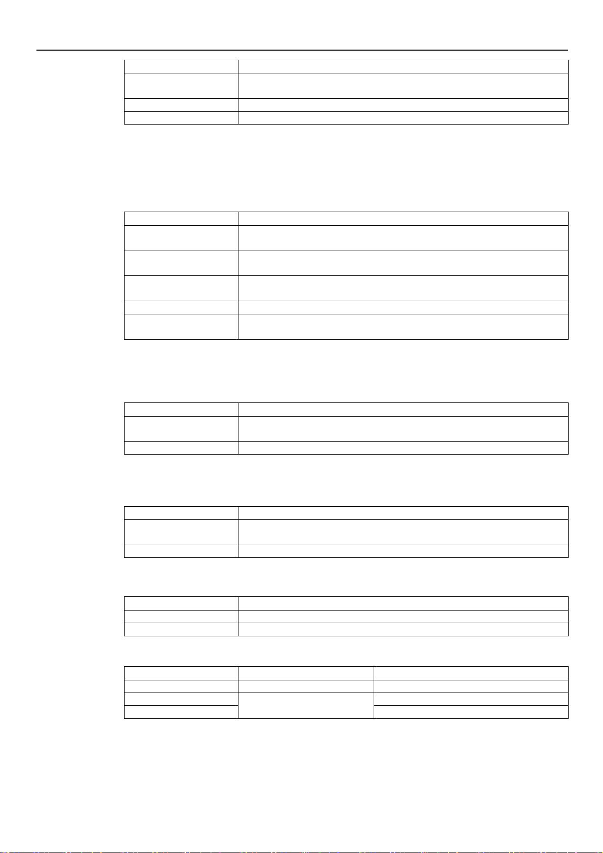
LED
Status
Off
The unit cannot detect any valid Modbus messages on the terminals provided for the
communication bus
Green steady
The unit has detected a communication bus on the provided terminals and has
recognised the correct addressing
Green flashing
The unit has detected a communication bus on the provided terminals and has not
been addressed correctly
From green steady to off
The unit has not detected a valid Modbus RTU message for at least 5 seconds
From green steady to
flashing
The unit has not been addressed correctly for at least 5 seconds
LED
Status
Off
The unit has received no valid requests from other BACnet MS/TP devices for at least
5 seconds
On steady
The unit is exchanging information with another BACnet MS/TP device
LED
Status
Off
The unit has received no valid requests from other pumps through the multi -pump
BUS for at least 5 seconds
On steady
The unit is exchanging information with another pump through the multi-pump BUS
LED
Status
Off
RS485 or wireless connection faulty or missing
Flashing
The unit is exchanging information with the communication module
LED on
Measurement active
Notes
10xRPM
Impeller rotation speed
The display shows the speed in 10xRPM
BAR
Hydraulic head
The display shows the value of the head in bar
PSI
The display shows the value of the head in psi
6.3.4 COM (communication)
Condition 1
The communication bus protocol is the Modbus RTU protocol; the P50 parameter is set to the
Modbus value
No optional communication module is used.
Condition 2
Condition 3
Condition 4
The communication bus protocol is the BACnet MS/TP protocol; the P50 parameter is set to
the BACnet value
No optional communication module is used.
A multi-pump control mode is selected (e.g. MSE or MSY)
No optional communication module is used.
The optional communication module is being used.
6.3.5 Unit of measurement
28
Page 29
6.4 Display
Display
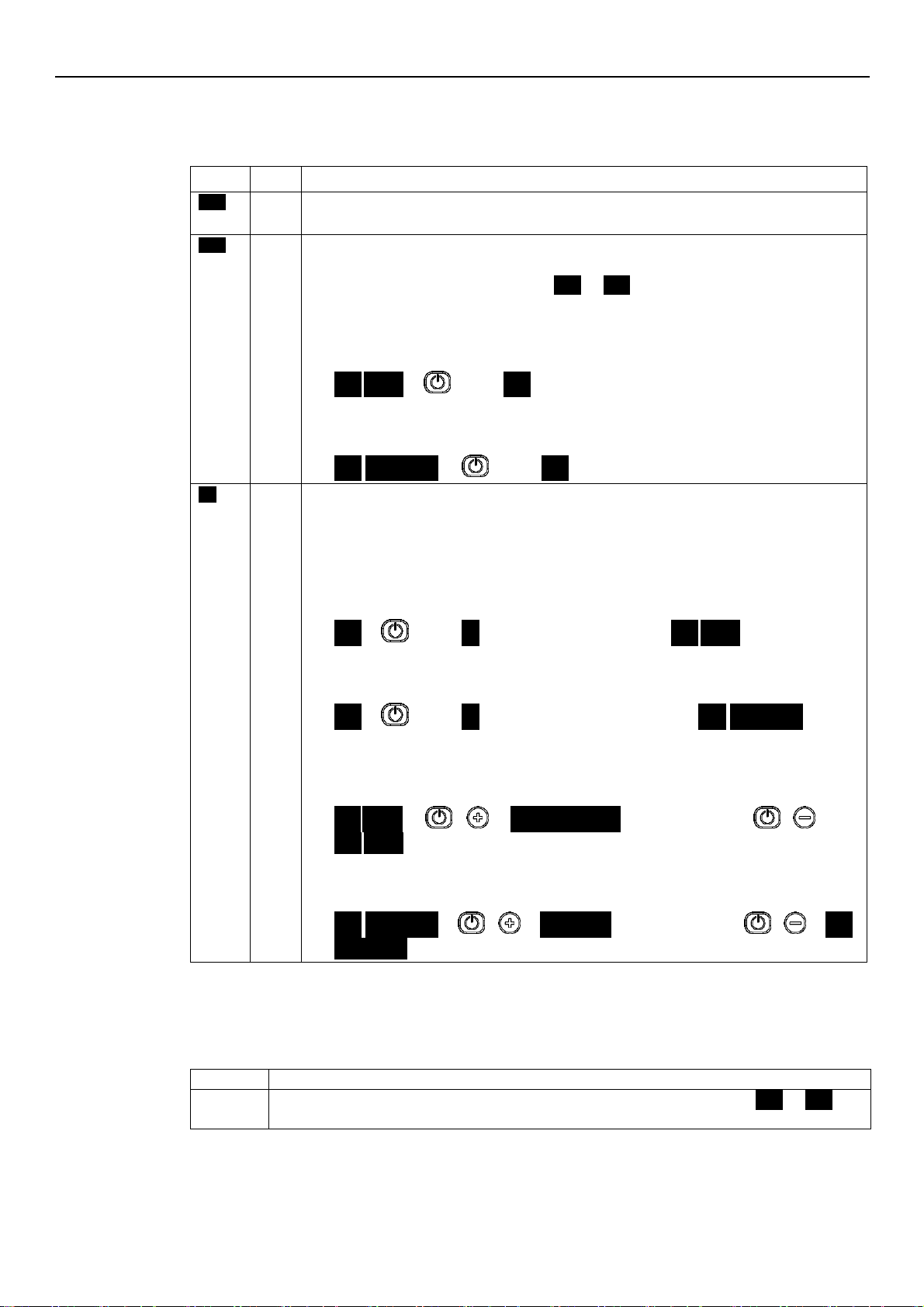
Mode
Description
OFF
OFF
Contacts 11 and 12 (see Par. 5.4) are not short-circuited.
Note: It has lower display priority than STOP mode.
STP
STOP
Pump stopped manually.
If the pump is switched on after setting P04 = OFF (see Par. 6.5.1), it is stopped so that the
motor is not in operation, and STP flashes (
STP ST
P
).
To manually stop the pump:
Example A.
HCS, MES, MSY control modes with initial required value (head) of 4.20 bar and minimum
value 0.5 bar:
4.20 BAR
press
STP
once.
Example B.
ACT control mode with initial required value (speed) of 200 10xRPM and minimum value 80
10xRPM:
200 10xRPM
press
STP
once.
ON
ON
Pump on; the motor starts following the selected control mode.
It appears for a few seconds when contacts 11 and 12 (see Par. 5.4) are short circuited and the
pump is not in STOP mode.
To manually set the pump to ON mode:
Example A.
HCS, MES, MSY control modes that reach a required value (head) of 4.20 bar, starting with a
minimum value of 0.5 bar after manual stop:
STP
press ON
once after a few seconds…
4.20 BAR
.
Example B.
ACT control mode that reaches a requested value (speed) of 200 10xRPM, starting with a
minimum value of 80 10xRPM after manual stop:
STP
press ON
once, and after a few seconds…
200 10xRPM
.
With the pump in operation, it is possible to display the Actual Head and the Actual Speed:
Example A
HCS, MES, MSY control modes with Actual Head 4.20 bar and corresponding Actual Speed of
352 10xRPM:
4
.20 BAR + 352 10XRPM
after 10 seconds or +
4.20 BAR
.
Example B
ACT control mode with Actual Speed 200 10xRPM and corresponding Actual Head of 2.37
bar:
200 10xRPM
+
2.37 BAR
after 10 seconds or +
200
10xRPM
.
Parameter
Description
Power on
If after switching ON, parameter Menu View is accessed with P23 = ON, P20 flashes:
P20 P20
.
Enter the password to display and change the pa rameters.
6.4.1 Main visualization
en – Original instructions
6.4.2 Parameters menu visualization
The parameter menu gives the possibility to:
select all the parameters (see Par. 6.5)
access Parameter View / Editing (see Par. 6.2).
29
Page 30
en – Original instructions
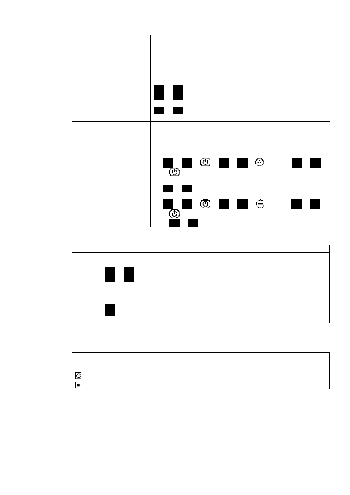
Password timeout
If with P23 = ON no button is pressed for over 10 minutes from the last
parameter Menu View, both the view and the editing of the parameters are
disabled.
Enter the password again to display and change the parameters.
Parameters Menu
With P23 = OFF, or after entering the password (P20), it is possible to both
display and edit the parameters. When accessing the Parameter Menu, the
display shows:
P01 P01
P02 P02
...
P69 P69
The flashing parameter, indicating the selection possibility.
Parameters Editing/Visualization
The value of a parameter may be changed using the buttons, or the Modbus
and BACnet communication protocols.
When returning to the Parameter Menu, the displayed parameter index is
increased automatically. For further information see Par. 6.5.
Example A (P20) from 000 to 066:
P20 P20 000 000
… until …
066 066
sets the desired value
P21 P21
Example 2 (P26) from 360 to 300:
P26 P26 360 360
… until…
300 300
sets the desired value
P26 P26
.
Parameter
Description
Alarm
In case of alarm, the corresponding code appears on the display in alternation to the Main View.
For example:
A01 3.56
(ex. BAR)
A02 285
(ex. 10xRPM)
…
Error
In case of error, the corresponding identification code appears on the display.
For example:
E01
E02
…
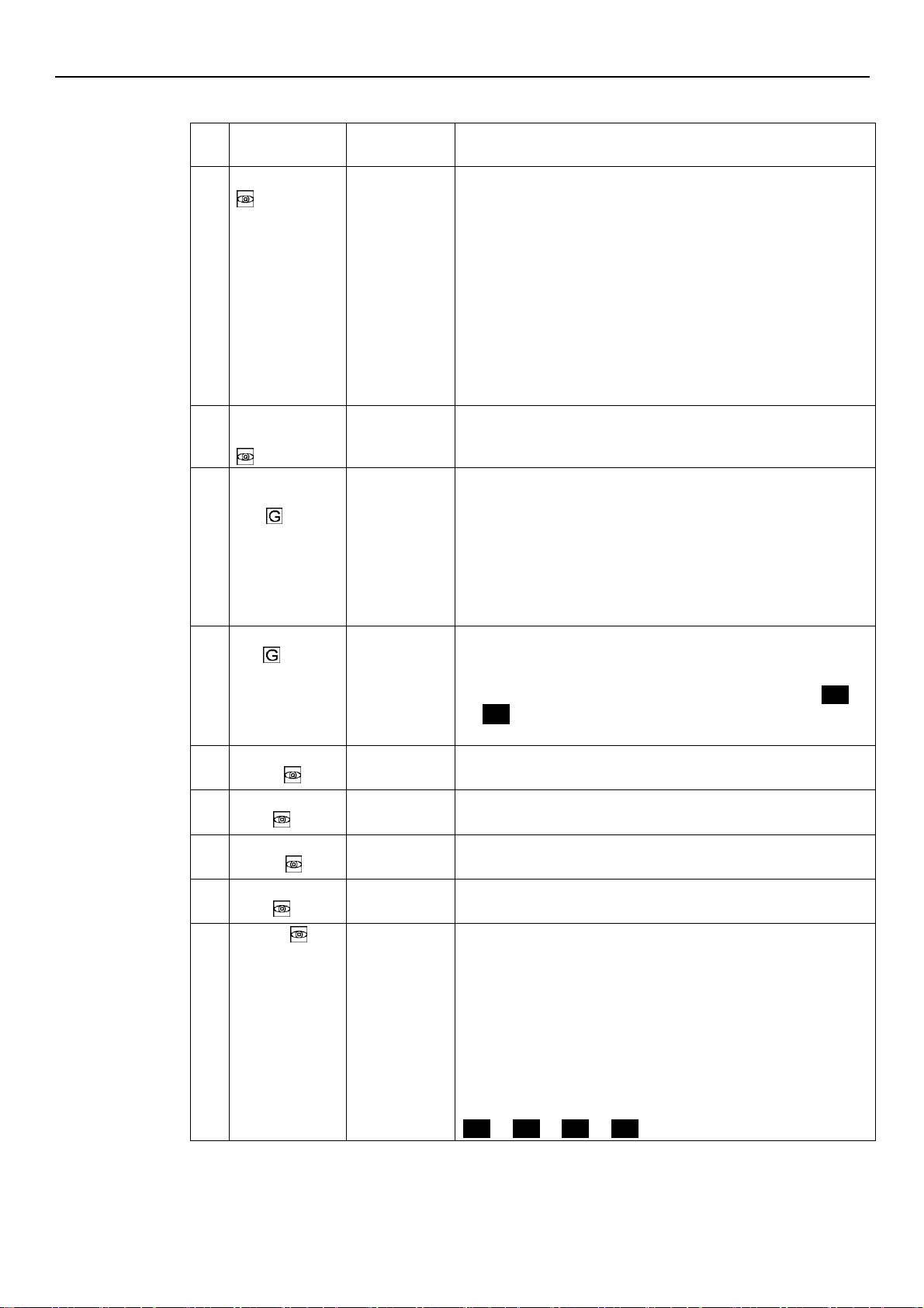
Mark
Parameter type
No mark
Applicable to all units
Global parameter, shared by all pumps in the same multi -pump system
Read only
6.4.3 Alarms and errors visualization
6.5 Software parameters
Parameters are marked differently in the manual depending on their type:
30
Page 31
6.5.1 Status Parameters
No.
Parameter
Unit of
measurement
Description
P01
Required value
bar/psi/
rpmx10
This parameter shows the SOURCE and the VALUE of the active
required value.
Visualization cycles between SOURCE and VALUE occur every 3
seconds.
SOURCES:
SP (SP): internal required value Setpoint related to the control
mode selected.
VL (UL): external required value speed Setpoint related to 0 -10V
input.
VALUE can represent a Speed or a Head, depending on the selected
control mode:
in case of Head, the unit of measure is defined by parameter P41.
P02
Effective
Required Value
bar/psi
Active required value calculated based on parameters P58 and P59.
This parameter is effective only in control modes MSE or MSY.
For further information on the calculation of P02, see Par. 6.6.3.
P03
Regulation
Restart Value [0100]
%
It defines the start value after the stop of the pump, as a percentage of
the P01 value. If the required value is met and there is no further
consumption, then the pump stops. The pump starts again when the
pressure drops below P03.
P03 is valid when:
Different from 100% (100%=off)
The control mode is HCS, MSE or MSY.
Default: 100%.
P04
Auto-start [OFFON]
If P04 = ON, then the pump starts automatically following a power
supply disconnection.
If the pump is switched on after setting P04 = OFF (see Par. 6.5.1), it is
stopped so that the motor is not in operation, and STP flashes (
STP
STP
).
Default: ON.
P05
Operating time
months
Total months of connection to the electric mains, to add to P06.
P06
Operating time
hours
h
Total hours of connection to the electric mains, to add to P05.
P07
Motor Time
Months
This parameter shows the total operating time months, to be added to
P08.
P08
Motor time
hours
h
This parameter shows the total operating time hours, to be added to
P07.
P09
1st error
This parameter stores the last error occurred in chronological order.
The information displayed switches through the values:
(Exx): xx indicates the error code
(Hyy): yy is the value of hours referred to P05-P06 when the error
Exx happened
(Dww): ww is the value of days referred to P05-P06 when the
error Exx happened
(Uzz): zz is the value of weeks referred to P05-P06 when the error
Exx happened
Example of visualisation:
E04 K10 d03 U15
en – Original instructions
31
Page 32
en – Original instructions
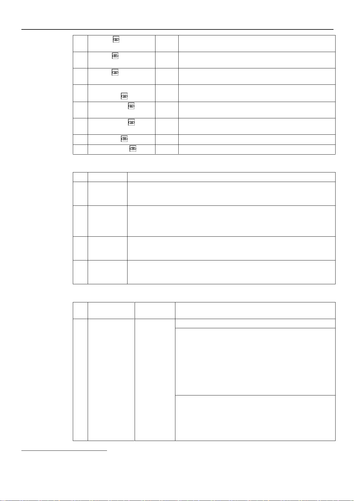
P10
2nd error
Saves the penultimate error in chronological occurred.
Other characteristics: like P09.
P11
3rd error
Saves the third from the last error in chronologica l occurred.
Other characteristics: like P09.
P12
4th error
Saves the fourth from the last error in chronological occurred.
Other characteristics: like P09.
P13
Power Module
Temperature
°C
Temperature of the power module.
P14
Inverter Current
A
This parameter shows the actual current supplied by the frequency
converter.
P15
Inverter Voltage
V
This parameter shows the actual estimated input voltage of the
frequency converter.
P16
Motor Speed
rpmx10
This parameter shows the actual motor rotational speed.
P17
Software version
This parameter shows the Control Board software version.
No.
Parameter
Description
P20
Password
entering [0999]
The user can enter here the system password, which gives access to all system paramet ers:
this value is compared with the one stored in P22.
When a correct password is entered, the system remains unlocked for 10 minutes.
P21
Jog mode
[MIN-MAX*]
It deactivates the internal controller of the unit and forces the actual Control Mode (ACT):
the motor starts and the value of P21 becomes the temporary ACT setpoint. It can be
changed by just entering a new value on P21 without confirming it; otherwise, it causes
immediate exit from temporary control.
P22
System
password [1999]
This is the system password, and must be the same as the password entered in P20.
Default: 66.
P23
Lock Function
[OFF, ON]
By using this function, the user can lock or unlock parameter setting in the main menu.
When ON, enter the P20 password to change the parameters.
Default: ON.
No.
Parameter
Unit of
measurement
Description
P25
Control mode
[ACT, HCS, MSE,
MSY]
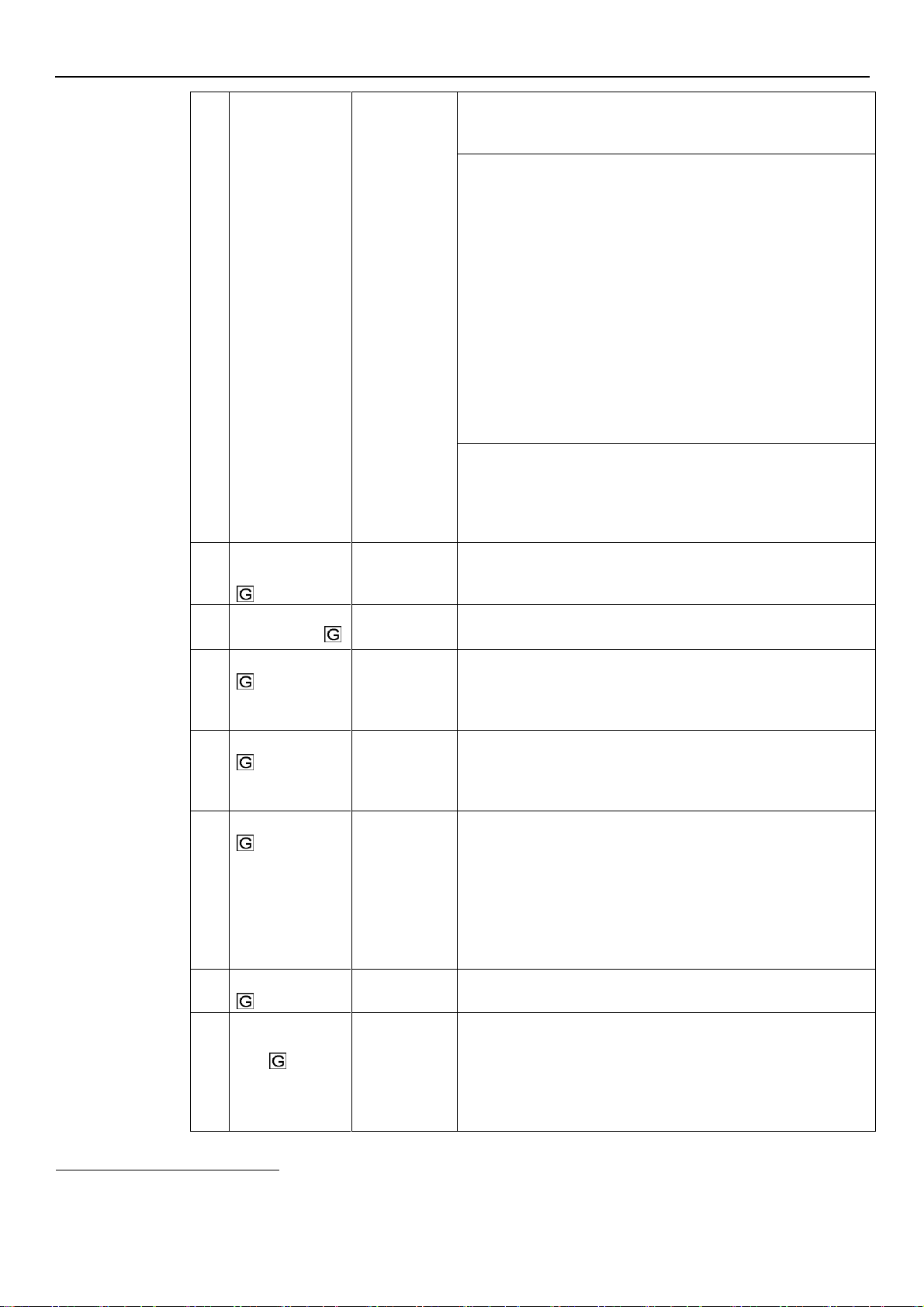
This parameter sets the Control Mode (default value: HCS)
ACT
: Actuator mode.
A single pump maintains a fixed speed at any flow rate. ACT will
always try to minimize the difference between the speed setpoint and
the actual rotational speed of the motor.
If a 0-10V signal is supplied to terminals 7 and 8, the pump
automatically switches to ACT mode, following the external signal, as
shown in figure 17.
If the external signal is missing, the pump remains in ACT mode, using
the value set as setpoint using the display.
HCS
: Hydrovar® Controller mode for Single pump.
The pump maintains a constant pressure at any flow rate: the
Hydrovar® algorithm, based on the set of parameters from P26 to P37
(see Par. 6.5.3), is implemented.
HCS mode must be set in conjunction with the use of an absolute
reading pressure sensor installed in the hydraulic circuit, which
6.5.2 Settings Parameters
6.5.3 Drive Configuration Parameters
*
Depending on the type of pump used
32
Page 33
en – Original instructions
supplies to the unit the pressure feedback signal: HCS will always try
to minimize the difference between the pressure setpoint and the
pressure feedback signal.
MSE
: Hydrovar® Controller mode for multiple pumps in Serial Cascade.
Pumps are managed in series: only the last activated pump modulates
the speed to maintain the set pressure, while all the others in
operation rotate at the maximum speed.
The set of pumps, connected to each other through the multi-pump
protocol, maintains a constant pressure at any flow rate: the
Hydrovar® algorithm, based on the set of parameters from P26 to P37
(see Par. 6.5.3), is implemented.
MSE mode must be set in conjunction with the use of absolute reading
pressure sensors, one for each pump, which supply to the set the
pressure feedback signal: MSE will always try to minimize the
difference between the pressure setpoint and the pressure feedback
signal.
Using the multi-pump protocol, it is possible to connect up to 3
pumps, all of the same type and with the same power.
MSY
: Hydrovar® Controller mode for Multiple pumps in Synchronous
Cascade.
The pumps are synchronised: they all keep the set pressure and
operate at the same speed.
Other characteristics: as for MSE mode.
P26
Max RPM set
[ACT set-Max*]
rpmx10
Maximum pump speed setup.
P27
Min RPM set
[Min*-ACT set]
rpmx10
Minimum pump speed setup.
P28
Ramp 1 [1-250]
s
This parameter adjusts the fast acceleration time.
It affects the control of the pump for HCS, MSE and MSY control
modes (also see Par. 6.6.2).
Default: 3 s.
P29
Ramp 2 [1-250]
s
This parameter adjusts the fast deceleration time
It affects the control of the pump for HCS, MSE and MSY control
modes (also see Par. 6.6.2).
Default: 3 s.
P30
Ramp 3 [1-999]
s
This parameter adjusts the slow acceleration.
It determines:
The Hydrovar®adjustment speed, in case of small flow rate
variations
The constant outgoing pressure.
The ramp depends on the system being controlled, and affects the
control of the pump in HCS, MSE and MSY modes (also see Par. 6.6.2).
Default: 35 s.
P31
Ramp 4 [1-999]
s
Adjustment of the slow deceleration time (also see Par. 6.6.2).
Other characteristics: as for Ramp 3.
P32
Ramp Speed Min
Acceleration [2.0-
25.0]
s
This parameter sets the fast acceleration time.
It represents the acceleration ramp used by the Hydrovar® controller
until the minimum speed of the pump is reached (P27).
It affects the control of the pump for HCS, MSE and MSY control
modes (also see Par. 6.6.2).
Default: 2.0 s.
*
Depending on the type of pump used
33
Page 34
en – Original instructions
P33
Ramp Speed Min
Deceleration [2.0-
25.0]
s
This parameter sets the fast deceleration time.
It represents the deceleration ramp used by the Hydrovar® controller for
stopping the pump once the minimum speed of the pump is reached (P27).
It affects the control of the pump for HCS, MSE and MSY control modes
(also see Par. 6.6.2).
Default: 2.0 s.
P34
Speed Min
Configuration [STP,
SMI]
This parameter defines the operation of the Hydrovar® controller once the
minimum speed of the pump is reached (P27):
STP
(STP): once the required pressure is reached and no further
request is made, the pump speed decreases to the selected P27 value:
Hydrovar® then keeps running for the selected time interval (P35), and
then stops automatically.
SNI
(SMI): once the required pressure is reached and no further
request is made, the pump speed decreases to the selected P27 value:
Hydrovar® continues running at the same speed. This parameter affects
the control of the pump for HCS, MSE and MSY control modes.
Default: STP
P35
Smin time [0-100]
s
This parameter sets the time delay before a shut-off below P27 occurs.
It is only used by the Hydrovar® controller if P34 = STP.
It affects the control of the pump for HCS, MSE and MSY control modes.
Default: 0 s.
P36
Window [0-100]
%
This parameter sets the ramp control interval, as a percentage of the
pressure setpoint.
It is used to define the range of pressures, around the setpoint, in which the
Hydrovar® controller uses slow acceleration and deceleration ramps instead
of fast ones.
It affects the control of the pump for HCS, MSE and MSY control modes
(also see Par. 6.6.2).
Default: 10%.
P37
Hysteresis [0-100]
%
This parameter sets the slow ramp hysteresis, as a percentage of P36.
It helps define the pressure range, around the setpoint, in which Hydrovar®
goes from slow acceleration ramp (P28) to slow deceleration ramp (P29).
The parameter affects the control of the pump for HCS, MSE and MSY
control modes (also see Par. 6.6.2).
Default: 80%.
P38
Speed Lift [0-MAX*]
rpmx10
This parameter sets the speed limit after which the linear increase of the
actual require value starts (P02), until the total increase (P39) at maximum
speed (P26).
Default: P27.
P39
Lift Amount [0-200]
%
This parameter sets the increase value of the actual required value (P02) at
the maximum speed (P26), measured as a percentage of the required value
(P01).
It determines the increase of the required pressure set, useful to
compensate for flow resistances at high flow rates.
Default: 0.
*
Depending on the type of pump used
34
Page 35
6.5.4 Sensor Configuration Parameters
No.
Parameter
Unit of
measurement
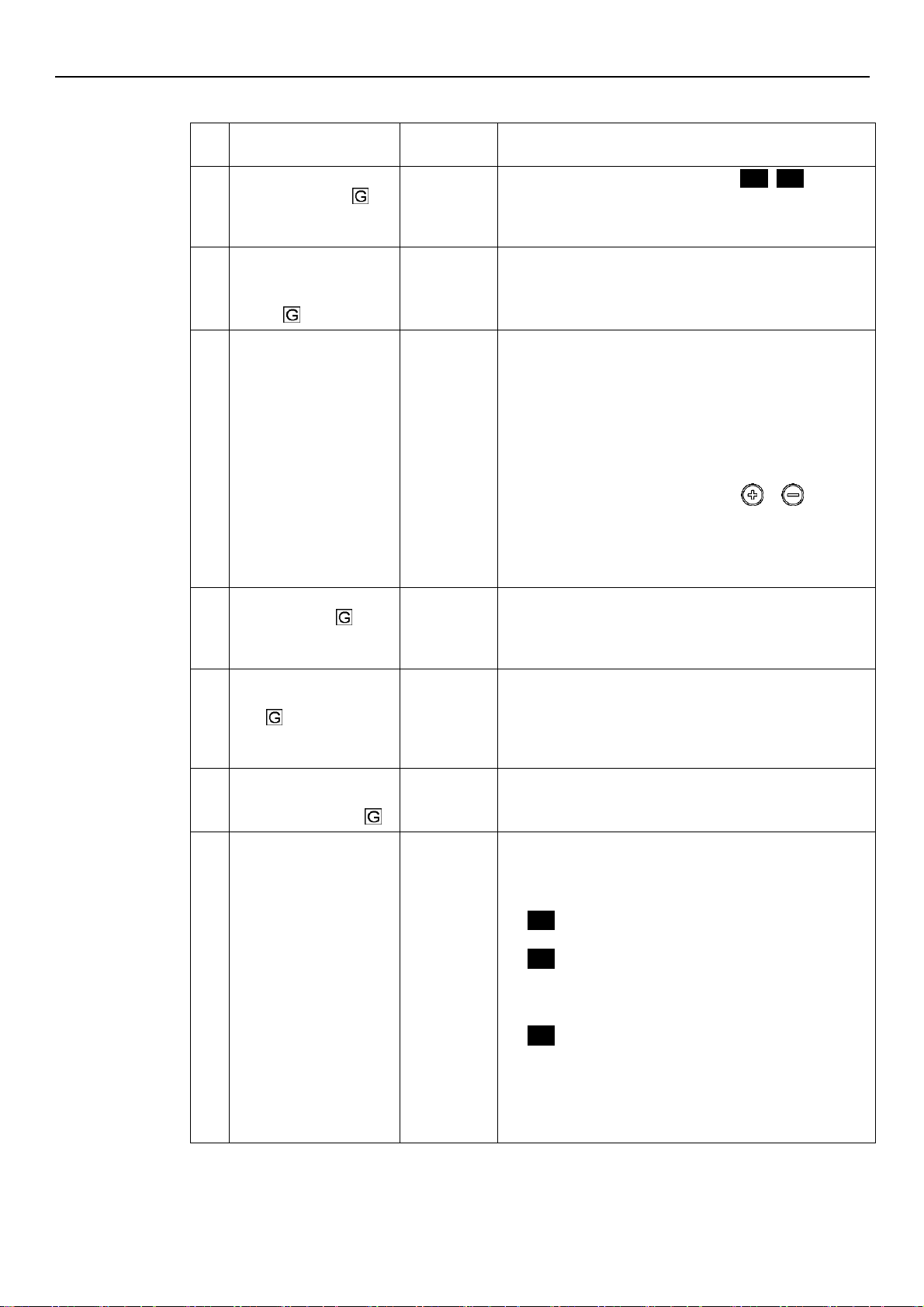
Description
P41
Pressure Sensor Unit Of
Measure [BAR, PSI]
This parameter sets the unit of measure
(
BAr, PSI
)
for the
pressure sensor.
It affect the head view LED parameter (see Par. 6.3.4).
Default: bar.
P42
Full scale value for
pressure Sensor 1 4-20mA
[0.0-25.0BAR] / [0.0363PSI]
bar/psi
This parameter sets the Full Scale value of the 4-20mA pressure
sensor connected to analog input 17 and 18.
Default: depending on the type of pump.
P44
Zero Pressure AutoCalibration
bar/psi
This parameter lets the user perform the initial auto-calibration
of the pressure sensor.
It is used to compensate for the offset signal of the sensor at
zero pressure caused by the tolerance of the sensor itself.
Procedure:
1. Access P44 when the hydraulic system is at 0 pressure (no
water inside), or with the pressure sensor disconnected
from the piping: the actual value of 0 pressure is displayed.
2. Start the auto-calibration by pressing or (see Par.
6.2).
3. At the end of the auto-calibration, the 0 (zero) pressure is
displayed, or the “---“ (---) message, if the sensor signal is
out of the permitted tolerance.
P45
Pressure Minimum
Threshold [0-42]
bar/psi
Setting the minimum pressure threshold.
If the system pressure falls below this threshold for the time
set in P46, a low pressure error E14 is generated.
Default: 0 bar.
P46
Pressure Minimum
Threshold - Delay Time [1100]
s
Time delay setup.
This parameter sets the time delay during which the unit
remains idle with a system pressure below P45, before
generating the low pressure error E14.
Default: 2 s.
P47
Pressure Minimum
Threshold – Automatic
Error Reset [OFF, ON]
Enabling/disabling of automatic unit attempts in case of low
pressure error.
Default: ON.
P48
Lack Of Water Switch
Input [DIS, ALR, ERR]
This parameter enables/disables the management of the lack
of input water (see Par. 4.3.3, terminals 13 and 14).
It defines the behaviour of the unit when the lack of water
input is enabled and the switch is open:
DIS
(DIS): the unit doesn’t manage the information
coming from the "lack of water" input
ALr
(ALr): the unit reads the "lack of water" Input
(enabled) and reacts, at the opening of the switch, by
displaying the corresponding alarm A06 on the display, and
keeping the motor running
Err
(Err): Err, the unit reads the Lack Of Water Input
(enabled) and reacts, at the opening of the switch, by
stopping the motor and generating the corresponding error
E11. The error condition is removed when the switch closes
again and the motor is started.
Default: ERR.
en – Original instructions
35
Page 36
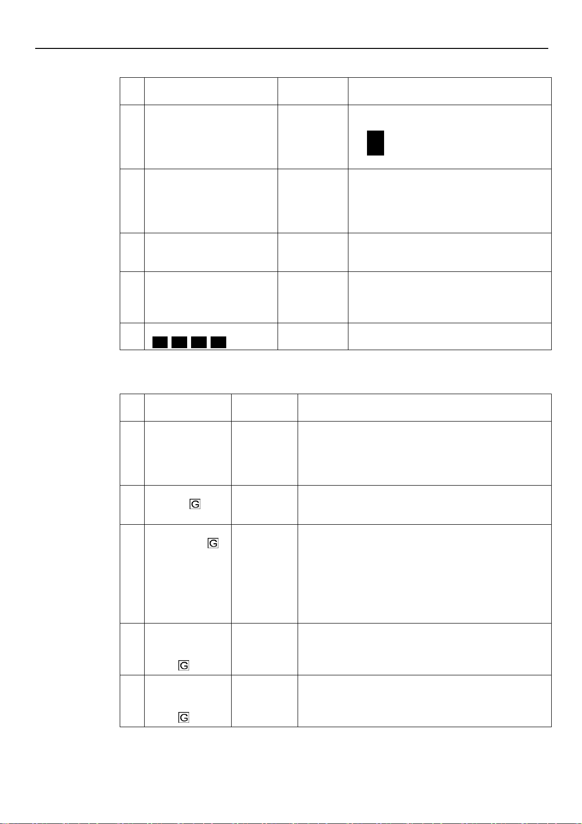
en – Original instructions
No.
Parameter
Unit of
measurement
Description
P50
Communication protocol [MOD,
BAC]
This parameter selects the specific protocol on the
communication port:
NOD
(MOD): Modbus RTU
BAC
(BAC): BACnet MS/TP.
Default: MOD.
P51
Communication protocol Address [1-247]/[0-127]
This parameter sets the desired address for the unit,
when connected to an external device, depending on
the protocol selected in P50:
MOD: any value in the 1-247 range
BAC: any value in the 0-127 range.
P52
Comm Protocol – BAUDRATE
[4.8, 9.6, 14.4, 19.2, 38.4, 56.0,
57.6 KBPS]
kbps
This parameter sets the desired baud rate for the
communication port.
Default: 9.6 kbps.
P53
BACnet Device ID Offset [0-999]
This parameter sets the hundreds, tens and units of
the BACnet Device ID.
Default: 002.
Device ID default: 84002.
P54
Comm Protocol – Configuration
[
8N1, 8N2, 8E1, 8o1
]
This parameter sets the length of the data bits, the
parity and the length of the STOP bits.
No.
Parameter
Unit of
measurement
Description
P55
Multipump –
Address [1-3]
This parameter sets the address of each pump based on the
following criteria:
Each pump needs an individual pump address (1 -3)
Each address may only be used once.
Default: 1.
P56
Multipump – Max
Units [1-3]
This parameter sets the maximum number of pumps operating at
the same time.
Default: 3.
P57
Multipump – Switch
Interval [0-250]
h
Setpoint of the main pump forced switch interval.
If the pump with priority 1 works in continuous mode until this time
is reached, the switch between this pump and the next is forced. If
on the other hand, the system stops completely due to the setpoint
being reached, with the next start priority 1 will be assigned in a
way to ensure an even distribution of the operating hours of all
pumps.
Default: 24 h.
P58
Multipump – Actual
Value Increase [0.0-
25.0BAR] / [0.0363PSI]
bar/psi
This parameter affects the calculation of P02, to improve the
Multipump control as described in paragraph 6.6.3.
Default: 0.35 bar.
P59
Multipump – Actual
Value Decrease [0.0-
25.0BAR] / [0.0363PSI]
bar/psi
This parameter affects the calculation of P02, to improve the multi pump control as described in paragraph 6.6.3.
Default: 0.15 bar.
6.5.5 RS485 Interface Parameters
6.5.6 Multi-pump configuration parameters
All these parameters affect MSE and MSY control modes.
36
Page 37
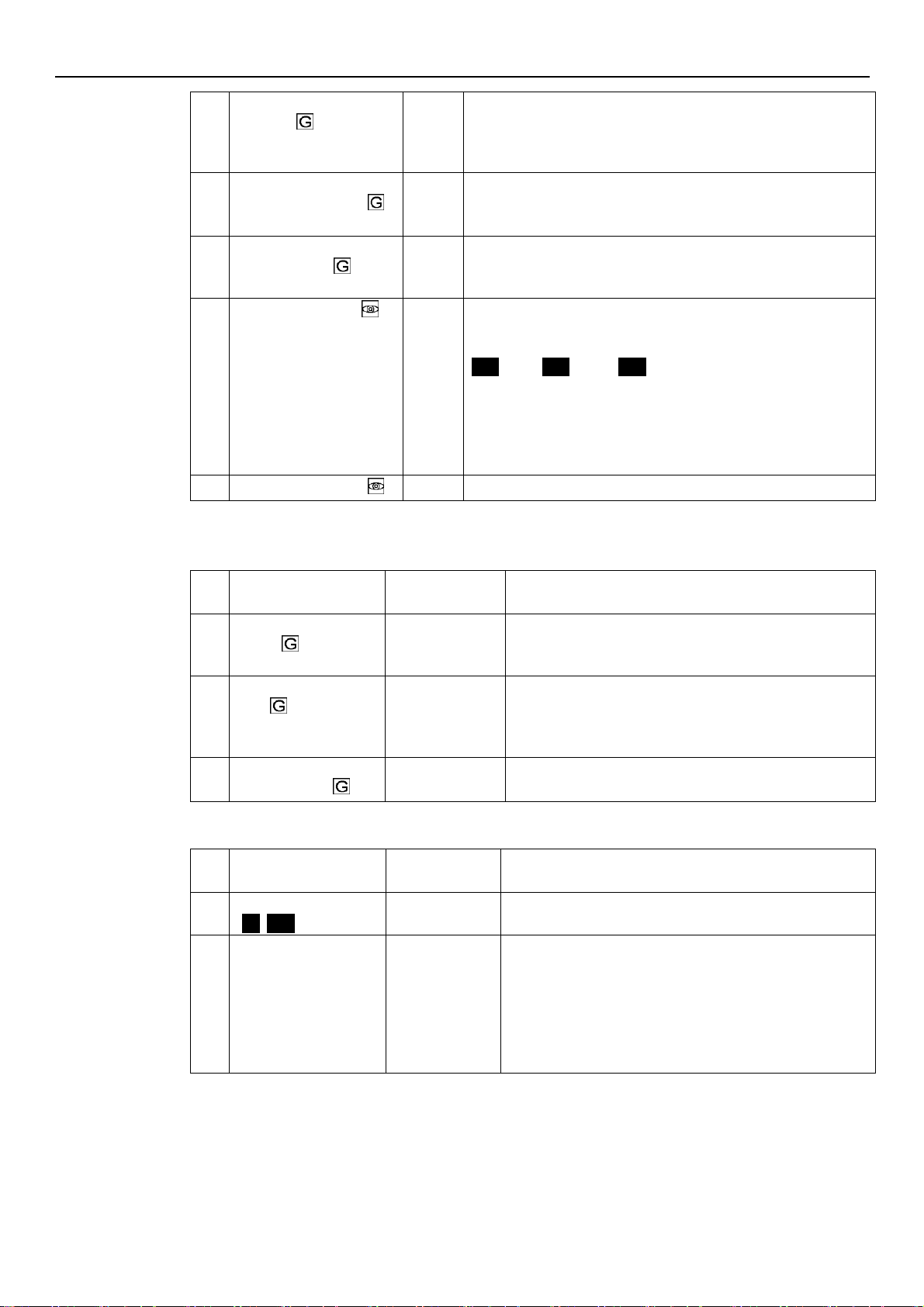
en – Original instructions
P60
Multipump – Enable Speed
[P27-P26]
rpmx10
This parameter sets the speed that a pump must reach before
starting the next assist pump, after a system pressure drop below the
difference between P02 and P59.
Default: depending on the type of pump.
P61
Multipump Synchronous –
Speed Limit [P27-P26]
rpmx10
This parameter sets the speed limit below which the first assist pump
stops.
Default: depending on the type of pump.
P62
Multipump Synchronous –
Window [0-100]
rpmx10
This parameter sets the speed limit for the stop of the next assist
pump.
Default: 150 rpmx10.
P63
Multipump – Priority
This parameter shows the pump priority value within the multi-pump
set.
This parameter displays the following information:
Pr1
(Pr1) ..
Pr3
(Pr3) or
Pr0
(Pr0)
where:
Pr1 .. PR3, indicate that the pump is communicating with others
pumps and its priority order, is equal to the visualized number.
Pr0 indicates that the pump does not detect the communication
with other pumps and is considered alone in the multi-pump bus
P64
Multipump – Revision
This parameter shows the multi-pump protocol revision value used.
No.
Parameter
Unit of
measurement
Description
P65
Test Run – Time Start
[0-100]
h
This parameter sets the time after which, once the pump has
stopped for the last time, the Test Run will start.
Default: 100 h.
P66
Test Run – Speed [MinMax]
rpmx10
This parameter sets the pump rotational speed for the Test
Run.
The Min and Max speeds depend on the pump type.
Default: 200 rpmx10.
P67
Test Run – Time
Duration[0-180]
s
This parameter sets the duration of the Test Run.
Default: 10 s.
No.
Parameter
Unit of
measurement
Description
P68
Default Values Reload
[
NO, rES
]
If set to RES, after confirmation this parameter performs a
factory reset that reloads the default parameter values.
P69
Avoid Frequent
Parameters Saving [NO,
YES]
This parameter limits the frequency with which the unit stores
the required value P02 in the EEPROM memory, in order to
extend its life.
This could be particularly useful in applications with BMS
control devices that require continuous variation of the value
for fine tuning purposes.
Default: NO.
6.5.7 Test Run Configuration Parameters
Test Run is a function that starts the pump after the last stop, in order to prevent it from blocking.
6.5.8 Special Parameters
37
Page 38
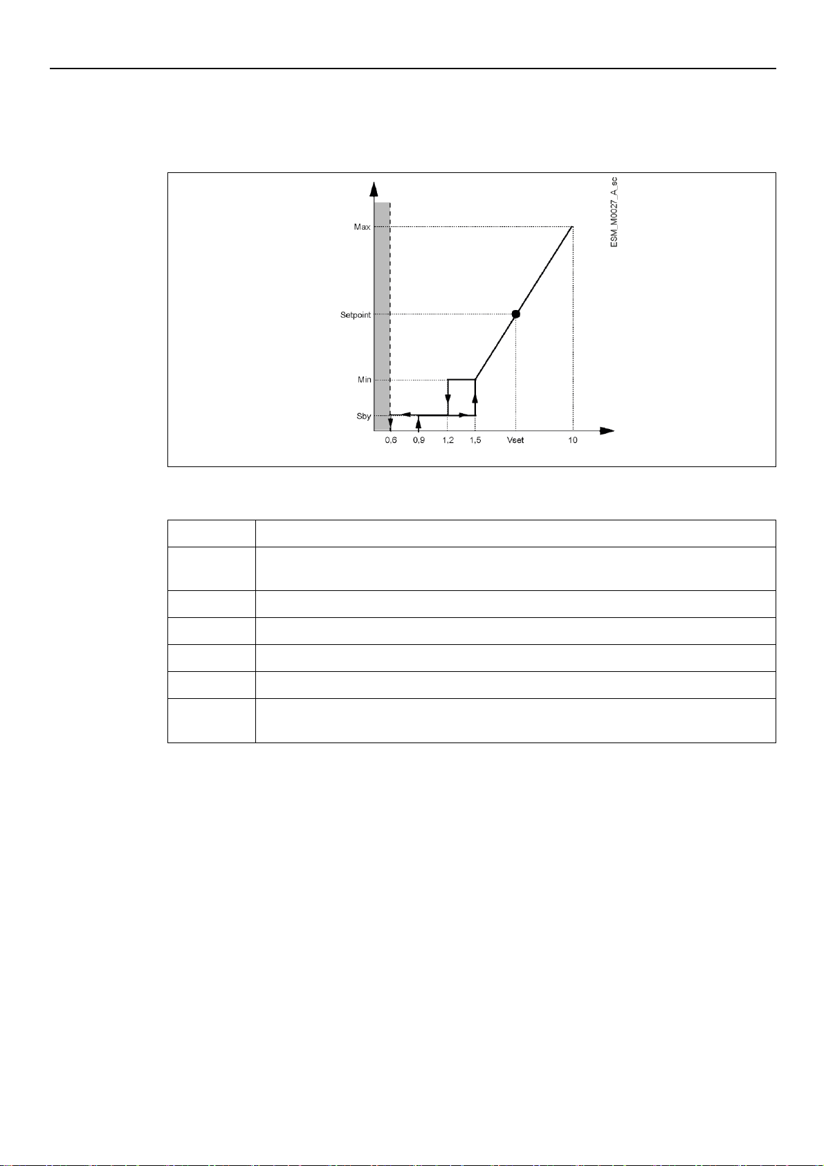
en – Original instructions
Figure 17: ACT control mode diagram
Table 12: Description
Grey area
Missing input Voltage detection threshold
Speed [rpm]
Actual speed relative to the 0-10V analogue input voltage value (see Par. 4.3.3, table 8 contacts
7 and 8)
Max
P26 (Max RPM set)
Min
P27 (Min RPM set)
Setpoint
Example of Actual Speed related to a specific Vset Voltage value
Sby
Input Voltage at which the motor goes in Stand By
Vin [V]
Input Voltage value to control the pump in ACT mode
Different thresholds are managed by the pump, from Non -detection to Max speed)
Vin [V]
Speed
[rpm]
6.6 Technical references
6.6.1
Graph
Example: ACT control mode with analog 0-10V input
For further information on the control mode and the ACT regulation parameters, see Par. 6.5.3.
38
Page 39
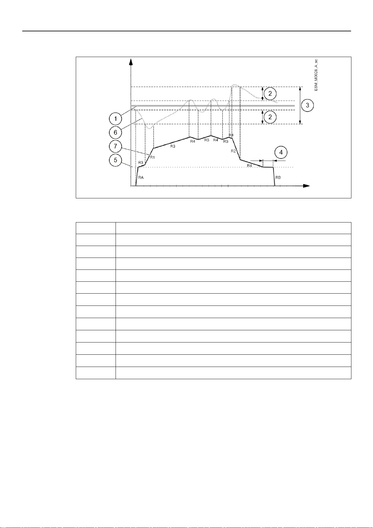
6.6.2 Example: Ramp Settings
Figure 18: Ramp settings
Table 13: Description
1
P01 (Required Value)
2
P37 (Adjustment hysteresis) as a % of P36 (Adjustment window)
3
P36 (Adjustment window) as a % of P01 (Required Value)
4
P35 (Minimum speed - Duration)
5
P27 (Minimum speed)
6
Actual Head
7
Actual Speed
RA
P32 (Acceleration ramp at startup)
RB
P32 (Deceleration ramp at shutdown)
R1
P28 (Ramp 1) - Fast ramp speed increase
R2
P29 (Ramp 2) - Fast ramp speed decrease
R3
P30 (Ramp 3) - Slow ramp speed increase
R4
P31 (Ramp 4) - Slow ramp speed decrease
H [bar]
t [s]
Graph
en – Original instructions
For further information on the adjustment of the ramps, see Par. 6.5.3.
6.6.3 Example: Effective Required Value
Pumps activation in cascade modes:
1. Lead pump reaches its P60 (Enable Speed).
2. Actual value falls to the cut in-value of the 1st assist pump.
The 1st assist pump switches on automatically. (Cut-in value = P01 (Required Value) - P59
(Actual Value Decrease))
3. A new required value, P02 (Effective Required Value) is calculated after the start up.
39
Page 40

en – Original instructions
Calculation of Effective Required Value in Cascade Serial (MSE):
K = number of active pumps
Pr = pump priority
P02 (Actual Required Value) = P01 (Required Value) + (K – 1) * P58 (Actual Value Increase) –
(Pr – 1) * P59 (Actual Value Decrease)
Calculation of Effective Required Value in Cascade Synchronous (MSY):
K = number of active pumps (K ≥ Pr)
P02 (Actual Required Value) = P01 (Required Value) + (K – 1) * (P58 – P59)
Behaviour of P58 (Actual Value Increase) and P59 (Actual Value Decrease):
if P58 (Actual Value Increase) = P59 (Actual Value Decrease) → Pressure constant,
independent of how many pumps are in operation.
if P58 (Actual Value Increase) > P59 (Actual Value Decrease) → Pressure rises when assist
pump switches on.
if P58 (Actual Value Increase) < P59 (Actual Value Decrease) → Pressure decreases when
assist pump switches on.
40
Page 41
en – Original instructions
DANGER: Electrical hazard
Before attempting to use the unit, check that it is unplugged and that the pump and the control
panel cannot restart, even unintentionally. This also applies to the auxiliary control circuit of
the pump.
Before any interventions on the unit, the network power supply and any other input voltages
must be disconnected for the minimum time indicated in Table 9 (the capacitors of the
intermediate circuit must be discharged by the built-in discharge resistors).
7 Maintenance
Precautions
1. Make sure that the cooling fan and the vents are free from dust.
2. Make sure that the ambient temperature is correct according to the limits of the unit.
3. Make sure that qualified personal perform all modifications of the unit.
4. Make sure that the unit is disconnected from the power supply before any work is carried out.
Always consider the pump and motor Instruction.
Function and parameter control
In case of changes to the hydraulic system:
1. Make sure that all functions and parameters are correct
2. Adjust the functions and parameters if necessary.
41
Page 42
en – Original instructions
Table 14: Alarm codes
code
Description
Cause
Remedy
A03
Derating
Temperature too high
Lower the room temperature
Lower the water temperature
Lower the load
A05
Data memory alarm
Data memory
corrupted
1. Reset the default parameters using parameter P68
2. Wait 10 s
3. Restart the pump
If the problem continues, contact Xylem or the Authorised
Distributor
A06
LOW alarm
Lack of water
detection (if P48= ALR)
Check the water level inside the tank
A15
EEPROM write
failure
Data memory
damaged
Stop the pump for 5 minutes and then restart it again; if the
problem continues, contact Xylem or the Authorised
Distributor
A20
Internal alarm
Stop the pump for 5 minutes and then r estart it again; if the
problem continues, contact Xylem or the Authorised
Distributor
A30
Multi-pump
connection alarm
Corrupted multi-pump
connection
Check the condition of the connection cables
Check that there are no address discrepancies
A31
Loss of multi-pump
connection
Loss of multi-pump
connection
Check the condition of the connection cables
Table 15: Error codes
code
Description
Cause
Remedy
E01
Internal
communication error
Internal communication
lost
Stop the pump for 5 minutes and then restart it again; if
the problem continues, contact Xylem or the Authorised
Distributor
E02
Motor overload
error
High motor current
Current absorbed by
the motor too high
Stop the pump for 5 minutes and then restart it again; if
the problem continues, contact Xylem or the Authorised
Distributor
8 Troubleshooting
In case of alarm or error, the display shows and ID code and the STATUS LED turns on (also see
Par. 6.3.2).
In case of several alarms and/or errors, the display shows the main one.
Alarms and errors:
are saved with date and time
can be reset by switching the unit off for at least 1 minute.
Errors cause the triggering of the status relay on the following terminal box pins:
single-phase version: pins 4 and 5
three-phase version: pins 24 and 25
8.1 Alarm codes
8.2 Error codes
42
Page 43
en – Original instructions
code
Description
Cause
Remedy
E03
DC-bus overvoltage
error
DC-bus overvoltage
External conditions cause the
operation of the pump from
generator
Check:
the system configuration
the position and integrity of the non-return
valves
E04
Rotor blocked
Motor stall
Loss of rotor synchronism or
rotor blocked by external
materials
Check that there are no foreign bodies
preventing the pump from turning
Stop the pump for 5 minutes and then start it
again
If the problem continues, contact Xylem or the
Authorised Distributor
E05
EEPROM Data
memory error
EEPROM Data memory corrupted
Stop the pump for 5 minutes and then restart it
again; if the problem continues, contact Xylem or
the Authorised Distributor
E06
Grid voltage error
Voltage supply out of operating
range
Check:
the voltage
the connection of the electric system
E07
Motor winding
temperature error
Motor thermal protection trip
Check for impurities near the impeller and
rotor. Remove them if necessary
Check the conditions of installation and the
water and air temperature
Wait for the motor to cool down
If the error persists, stop the pump for 5
minutes and then start it again
If the problem continues, contact Xylem or the
Authorised Distributor
E08
Power module
temperature error
Frequency converter thermal
protection trip
Check the conditions of installation,and the air
temperature
E09
Generic hardware
error
Hardware error
Stop the pump for 5 minutes and then restart it
again; if the problem continues, contact Xylem or
the Authorised Distributor
E11
LOW error
Lack of water detection (if P48=
ERR)
Check the water level inside the tank
E12
Pressure sensor
error
Missing pressure sensor (not
present in ACT mode)
Check the condition of the sensor connection
cables
E14
Low pressure error
Pressure below minimum
threshold (not present in ACT
mode)
Check the settings of parameters P45 and P46
E15
Loss of phase error
One of the three power supply
phases is missing (three-phase
versions only)
Check the connection to the power supply
network
E30
Multi-pump
protocol error
Incompatible multi-pump
protocol
Bring all the units to the same firmware version
See also Par. 6.3.2 and Par. 6.4.3.
43
Page 44
en – Original instructions
Table 16: Electrical, Environmetal and Installation specifications
e-SM Drive model
103
105
107
111
115
303
305
307
311
315
322
Input
Input frequency [Hz]
50/60 ± 2
Main supply
LN
L1 L2 L3
Nominal input voltage [V]
208-240 ±10%
208-240 / 380-460 ±10%
380-460
±10%
Maximum current
absorbed (AC) in
continuous service (S1) [A]
See data plate
PDS Efficiency Class
IES2
Output
Min.-Max. Speed [rpm]
800-3600
Leakage Current [mA]
< 3,5
I/O auxiliar + 15VDC
power supply [mA]
Imax < 40
Fault signal relay
1 x NO Vmax < 250 [VAC] , Imax < 2 [A]
1 x NO Vmax < 250 [VAC] , Imax < 2 [A]
Motor status relay
-
1 x NO Vmax < 250 [VAC] , Imax < 2 [A]
EMC (Electro Magnetic
Compatibility)
See Par. Declarations.
Installations must be performed in accordance with the EMC good practice guidelines
(e.g. avoid "eyebolts" on the transmission side)
Sound pressure LpA
[dB(A)] @ [rpm]
< 62 @3000
< 66 @3600
Insulation class
155 F
Protection class
IP 55, Enclosure Type 1
Protect the product from direct sunlight and rainfall
Relative humidity (storage
& operating)
5%-95% UR
Storage temperature [°C]
/[°F]
-25-65 / -13-149
Operating temperature
[°C] /[°F]
-20-50 / -4-122
Air Pollution
Pollution Degree 2
Installation altitude a.s.l.
[m] / [ft]
< 1000 / 3280
Derating may occur at higher altitudes
9 Technical Data
44
Page 45
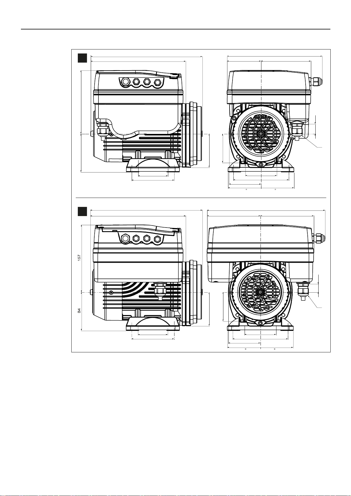
9.1 Dimensions and weights
Figure 19: Dimensions
B1
224
70
E1
80 117
224
74
155
E2
B5
149
B4
B5
68
23
ESM_M0003_D_sc
B1
224
277
125 125
19
B5
68
70
E1
74
155
E2
B5
ESM_T0025_A_sc
1~
3~
D3
D3
en – Original instructions
45
Page 46
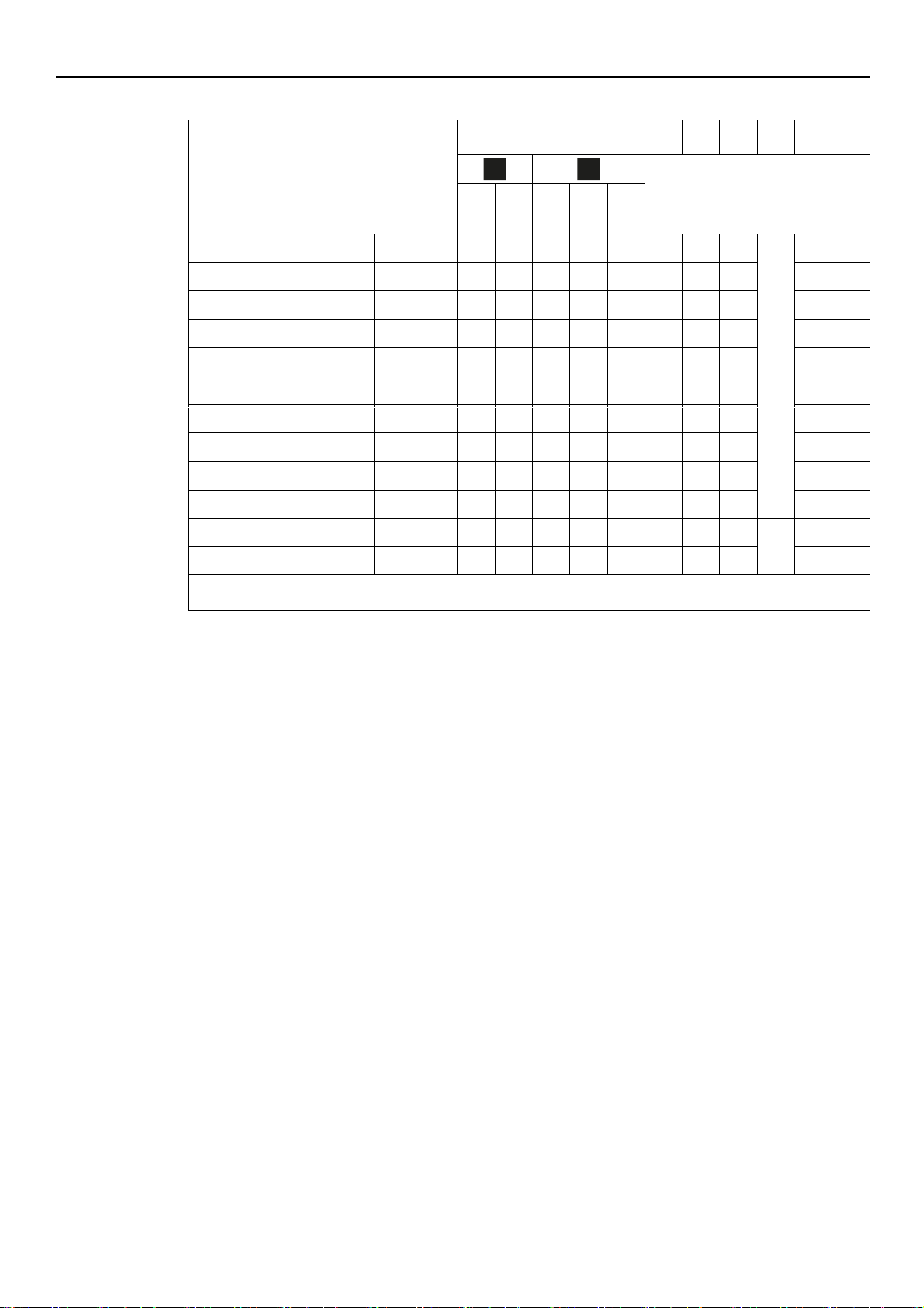
en – Original instructions
Table 17: Dimensions and weights
Model
Net weight (motor + drive)
[kg]
B1
B4
B5
D3
E1
E2
[mm]
103
105
107
111
115
303
305
307
311
315
322
ESM90R...LNEE
7.4
8.9
13
14.4
16
376 - 79
M20
- - ESM90RS8...LNEE
7.3
8.8
12.8
14.2
15.8
343 - 79 - -
ESM90R...B14-SVE
7.5 9 13.1
14.5
16
292 - 79 - -
ESM90R...B5
7.5 9 13.1
14.5
16
292 - 100 - -
ESM80...HMHA
80...HMHA US
80...HMHA EU
7.5 9 13
14.5
16
263
90
79
100
125
ESM80...HMHB
80...HMHB US
80...HMHB EU
7.6
9.2
13.2
14.6
16.1
268
90
80
100
125
ESM80...HMVB
80...HMVB US
80...HMVB EU
7.4
8.9
13
14.4
16
268 - 80 - -
ESM80...HMHC
80...HMHC US
80...HMHC EU
7.9
9.4
13.4
14.8
16.4
272
90
91
100
125
ESM80...HMVC
80...HMVC US
80...HMVC EU
7.6
9.1
13.2
14.6
16.2
272 - 91 - -
ESM80...BG
7.3
8.8
12.9
14.3
15.9
282 - 108 - -
ESM90R...56J
7.5
9.1
13
14.5
16.1
307
89
83
NPT
1/2"
76
124
ESM90R...56C
7.2
8.8
12.6
14.3
15.8
294 - 83 - -
... = 103, 105, 107, 111, 115, 303, 305, 307, 311, 315, 322
- = motor foot not found
1~
3~
46
Page 47

10 Declarations
Montecchio Maggiore, 22/02/2017
Amedeo Valente
(Director of Engineering and
Research & Development)
rev.02
Signed for and on behalf of: Xylem Service Italia S.r.l.
Montecchio Maggiore, 22/02/2017
Amedeo Valente
(Director of Engineering and R&D)
rev.01
10.1 EC Declaration of Conformity (Original)
Xylem Service Italia S.r.l., with headquarters in Via Vittorio Lombardi 14 - 36075 Montecchio
Maggiore VI - Italy, hereby declares that the product:
Electric pump with integrated variable speed drive, pressure transmitter and 2 metre cable for the
transmitter (see adhesive on the first page)
fulfils the relevant provisions of the following European Directives:
Machinery 2006/42/EC (ANNEX II - natural or legal person authorised to compile the technical
file: Xylem Service Italia S.r.l.)
Eco-design 2009/125/EC, Regulation (EU) no. 547/2012 (water pump) if MEI marked,
and the following technical standards
EN 809:1998+A1:2009, EN 60335-1:2012+A11: 2014, EN 60335-2-
41:2003+A1:2004+A2:2010, EN 62233:2008
EN 50598-1:2014, EN 50598-2:2014+A1:2016
en – Original instructions
10.2 EU Declaration of Conformity (No EMCD19)
1. Apparatus model/Product:
see adhesive on the first page
2. Name and address of the manufacturer:
Xylem Service Italia S.r.l.
Via Vittorio Lombardi 14
36075 Montecchio Maggiore VI
Italy
3. This declaration of conformity is issued under the sole responsibility of the manufacturer.
4. Object of the declaration:
Electric pump with integrated variable speed drive, pressure transmitter and 2 metre cable for
the transmitter (see adhesive on the first page)
5. The object of the declaration described above is in conformity with the relevant Union
harmonisation legislation:
Directive 2014/30/EU of 26 February 2014 (electromagnetic compatibility)
6. References to the relevant harmonised standards used or references to the other technical
specifications, in relation to which conformity is declared:
EN 60730-1:2011, EN 61800-3:2004+A1:2012 (Category C2),
EN 55014-1:2006+A1:2009+A2:2011, EN 55014-2:1997+A1:2001+
A2:2008, EN 61000-6-2:2005, EN 61000-6-3:2007+A1:2011
7. Notified body: -
8. Additional information: -
Lowara is a trademark of Xylem Inc. or one of its subsidiaries.
47
Page 48

Xylem Service Italia S.r.l.
Via Vittorio Lombardi 14
36075 – Montecchio Maggiore (VI) - Italy
www.xyleminc.com/brands/lowara
Lowara is a trademark of Xylem Inc. or one of its subsidiaries.
© 2018 Xylem, Inc.
 Loading...