

Page 1
Installation, Operation
and Maintenance manual
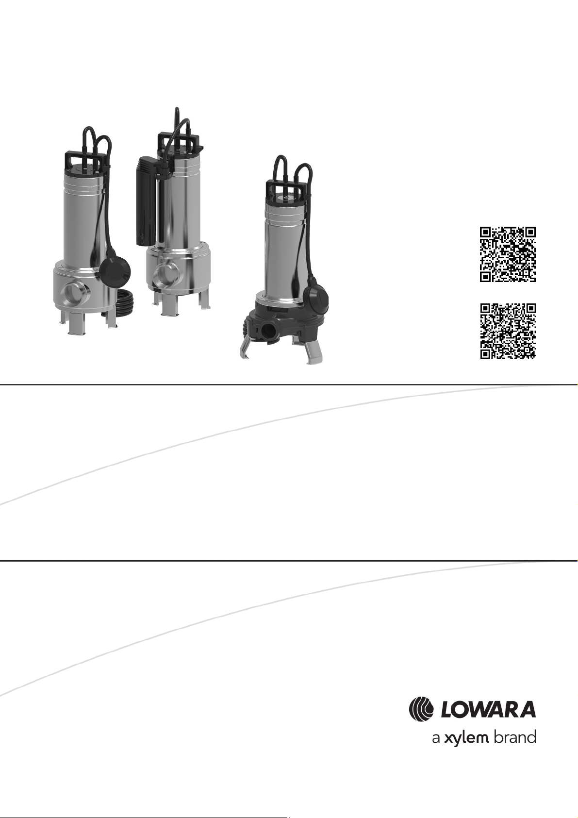
DOMO
DOMO GRI
DOMO, DOMO GRI
Submersible pump u
nits
Page 2

en – Original instructions
Table of Contents
1 Introduction and Safety ............................................................................................................................................ 4
1.1 Introduction ...................................................................................................................................................... 4
1.2 Safety ................................................................................................................................................................ 4
1.2.1 Danger levels and safety symbols ............................................................................................................... 4
1.2.2 User safety .................................................................................................................................................... 5
1.2.3 Protection of the environment ..................................................................................................................... 6
1.2.4 Sites exposed to ionizing radiations............................................................................................................ 6
2 Handling and Storage ............................................................................................................................................... 7
2.1 Handling of the packed unit ............................................................................................................................ 7
2.2 Unit inspection upon delivery .......................................................................................................................... 7
2.3 Unit handling .................................................................................................................................................... 8
2.4 Storage ............................................................................................................................................................. 8
3 Technical Description ............................................................................................................................................... 9
3.1 Designation ...................................................................................................................................................... 9
3.2 Denomination of the models ........................................................................................................................... 9
3.3 Data plate ......................................................................................................................................................... 9
3.4 Identification code ......................................................................................................................................... 10
3.5 Names of the main components ................................................................................................................... 11
3.6 Intended use ................................................................................................................................................... 11
3.7 Improper use .................................................................................................................................................. 11
4 Installation ............................................................................................................................................................... 13
4.1 Precautions ..................................................................................................................................................... 13
4.2 Mechanical installation ................................................................................................................................... 13
4.2.1 Installation area .......................................................................................................................................... 13
4.2.2 Permitted positions .................................................................................................................................... 14
4.2.3 Permanent installation on support base ................................................................................................... 14
4.2.4 Permanent installation with quick coupling .............................................................................................. 14
4.3 Start and stop levels ....................................................................................................................................... 16
4.4 Hydraulic connection ..................................................................................................................................... 17
4.4.1 Guidelines for the hydraulic system .......................................................................................................... 17
4.5 Electrical connection ...................................................................................................................................... 18
4.5.1 Ground ........................................................................................................................................................ 19
4.5.2 Guidelines for electrical connection .......................................................................................................... 19
4.5.3 Guidelines for the control electric panel ................................................................................................... 19
5 Use and operation .................................................................................................................................................. 20
5.1 Precautions ..................................................................................................................................................... 20
5.2 Rotation direction check (three-phase motors) ............................................................................................ 21
2 DOMO, DOMO GRI - Installation, Operation and Maintenance Manual
Page 3

en – Original instructions
5.3 Starting and stopping .................................................................................................................................... 21
6 Maintenance ............................................................................................................................................................ 22
6.1 Precautions ..................................................................................................................................................... 22
6.2 Maintenance every 6 months of operation ................................................................................................... 22
6.3 Long periods of inactivity ............................................................................................................................... 22
6.4 Spare parts ordering ...................................................................................................................................... 22
7 Troubleshooting...................................................................................................................................................... 23
7.1 Precautions ..................................................................................................................................................... 23
7.2 The unit does not start ................................................................................................................................... 23
7.3 The thermal overload protection triggers ..................................................................................................... 23
7.4 The unit runs but there is little or no flow rate .............................................................................................. 24
7.5 The unit never stops ....................................................................................................................................... 24
8 Technical Information ............................................................................................................................................. 25
8.1 Applications .................................................................................................................................................... 25
8.2 Operating environment ................................................................................................................................. 25
8.3 Maximum head ............................................................................................................................................... 26
8.4 Maximum number of starts per hour ............................................................................................................. 26
8.5 Mechanical characteristics ............................................................................................................................. 26
8.6 Electrical specifications .................................................................................................................................. 27
8.7 Sound pressure .............................................................................................................................................. 27
8.8 Dimensions and weights ................................................................................................................................ 27
9 Disposal ................................................................................................................................................................... 30
9.1 Precautions ..................................................................................................................................................... 30
10 Declarations ........................................................................................................................................................ 31
10.1 EC Declaration of Conformity (Original) ....................................................................................................... 31
10.2 EU Declaration of Conformity (n. EMCD30).................................................................................................. 31
11 Warranty ............................................................................................................................................................. 32
11.1 Information ..................................................................................................................................................... 32
DOMO, DOMO GRI - Installation, Operation and Maintenance Manual 3
Page 4
en – Original instructions
CAUTION:
This manual is an integral part of the unit. Make sure to have read and understood the manual
before installing the unit and putting it to use. The manual must always be
the user, stored in the proximity of the unit, and well kept.
Hazard level
Indication
DANGER:
It identifies a dangerous situation which, if not avoided,
WARNING:
It identifies a dangerous situation which, if not avoided, may
CAUTION:
It identifies a dangerous situation which, if not avoided, may
NOTICE:
It identifies a situation which, if not avoided, may cause
1 Introduction and Safety
1.1 Introduction
Purpose of this manual
This manual provides information on how to do the following in the correct manner:
• Installation
• Operation
• Maintenance.
Supplementary instructions
The instructions and warnings of this manual apply to the standard unit as described in the sale
documentation. Special version pumps may be supplied with supplementary instruction
manuals. For situations not considered in the manual or in the sales document, contact Xylem
or the Authorised Distributor.
1.2 Safety
1.2.1 Danger levels and safety symbols
Before using the unit, the user must read, understand and comply with the indications of the
danger warnings in order to avoid the following risks:
• Injuries and health hazards
• Damage to the product
• Unit malfunction.
Danger levels
causes serious injury, or even death.
made available to
cause serious injury, or even death.
cause small or medium level injuries.
damage to property but not to people.
4 DOMO, DOMO GRI - Installation, Operation and Maintenance Manual
Page 5
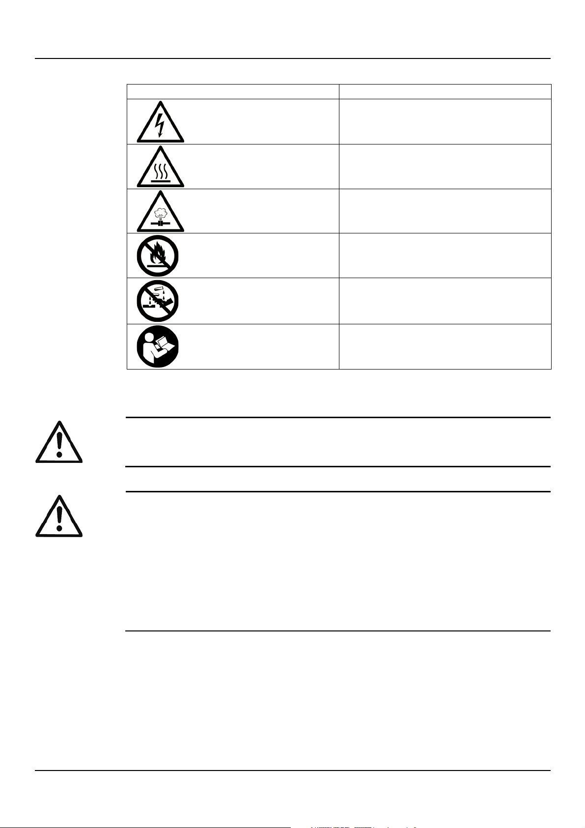
Complementary symbols
Symbol
Description
Electrical hazard
Hot surface hazard
Danger, system pressurized
Do not use flammable liquids
Do not use corrosive liquids
Read the instruction manual
WARNING:
This unit must be used only
the risks and avoid hazards during installation, use and maintenance of the unit.
WARNING:
•
•
not play with the product.
en – Original instructions
1.2.2 User safety
Strictly comply with current health and safety regulations.
Inexperienced users
For EU countries: this product may be used by children aged 8 years and above and
persons with reduced physical, sensory or mental capabilities, or who lack experience and
knowledge, provided that they are being supervised and have been instructed on how to
use it safely, and understand the hazards involved. Children must not play with the product.
Cleaning and maintenance must not be carried out by children without supervision.
For countries outside the EU: this product is not intended for use by persons (including
children) with reduced physical, sensory or mental capabilities, or who lack experience and
knowledge, unless they are being supervised and have been instructed on how to use it by
a person responsible for their safety. Children should be supervised to ensure that they do
by qualified users. Qualified users are people able to recognise
DOMO, DOMO GRI - Installation, Operation and Maintenance Manual 5
Page 6

en – Original instructions
WARNING:
It is prohibited to dispose of lubricating fluids and other hazardous substances in the
environment.
WARNING: Ionizing radiation hazard
If the
for the protection of people. If the unit needs to be despatched, inform the carrier and the
recipient accordingly, so that appropriate safety measures can be put in place.
1.2.3 Protection of the environment
Disposal of packaging and product
Comply with the current regulations on sorted waste disposal.
Leaking of fluid
The unit contains a small quantity of lubricant oil: always put in place the necessary measures
to ensure that any spilled lubricant does not disperse in the environment.
1.2.4 Sites exposed to ionizing radiations
unit has been exposed to ionizing radiations, implement the necessary safety measures
6 DOMO, DOMO GRI - Installation, Operation and Maintenance Manual
Page 7
2 Handling and Storage
WARNING: Crushing hazard (limbs)
The unit and its components may be heavy: risk of crushing.
WARNING:
Always wear personal protective equipment.
WARNING:
Check the gross weight marked on
WARNING:
Handle the unit in compliance with the current regulations on "manual load handling", to avoid
undesirable ergonomic conditions causing risks of back
WARNING:
Take appropriate measures during transport, installation and storage to prevent contamination
from external substances.
CAUTION: Cut and abrasion hazard
Always wear
2.1 Handling of the packed unit
the packaging.
en – Original instructions
The Manufacturer delivers the unit and its components in a cardboard box.
2.2 Unit inspection upon delivery
Inspect the package
1. Check that quantity, descriptions and product codes match the order.
2. Check the packaging for any damage or missing components.
3. In case of immediately detectable damage or missing parts:
- accept the goods with reserve, indicating any findings on the transport document, or
- reject the goods, indicating the reason on the transport document.
In both cases, promptly contact Xylem or the Authorised Distributor from whom the product
was purchased.
Unpacking and inspection of the unit
personal protective equipment.
-spine injury.
1. Remove packing materials from the product.
2. Check the unit for integrity and to make sure that there are no missing components.
3. In case of damage or missing components, promptly contact Xylem or the Authorised
Distributor.
DOMO, DOMO GRI - Installation, Operation and Maintenance Manual 7
Page 8
en – Original instructions
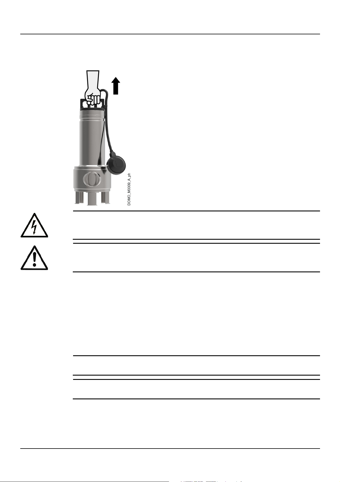
DANGER: Electrical hazard
Holding the unit by the
WARNING:
During handling, make sure to avoid injury to people and animals, and/or damage to
NOTICE:
Do not place heavy loads on top of the unit.
NOTICE:
Protect the unit from collisions.
2.3 Unit handling
Lift the unit using the handle.
2.4 Storage
Storage of the packed unit
The unit must be stored:
• In a covered and dry place
• Away from heat sources
• Protected from dirt
• Protected from vibrations
• At an ambient temperature down to -30°C (-22°F), and relative humidity between 5% and
95%.
supply cord or the float switch is strictly forbidden.
property.
Long-term storage of the unit
1. Completely empty the unit manually by tilting it towards the discharge port.
2. Follow the same instructions for the storage of the packed unit.
For further information about preparation for long-term storage, please contact Xylem or the
Authorised Distributor.
8 DOMO, DOMO GRI - Installation, Operation and Maintenance Manual
Page 9
3 Technical Description
Series
Description
DOMO
Submersible pump units for draining wastewater with two-channel or vortex (DOMO VX)
impeller
DOMO GRI
Submersible pump units for draining wastewater with grinding system
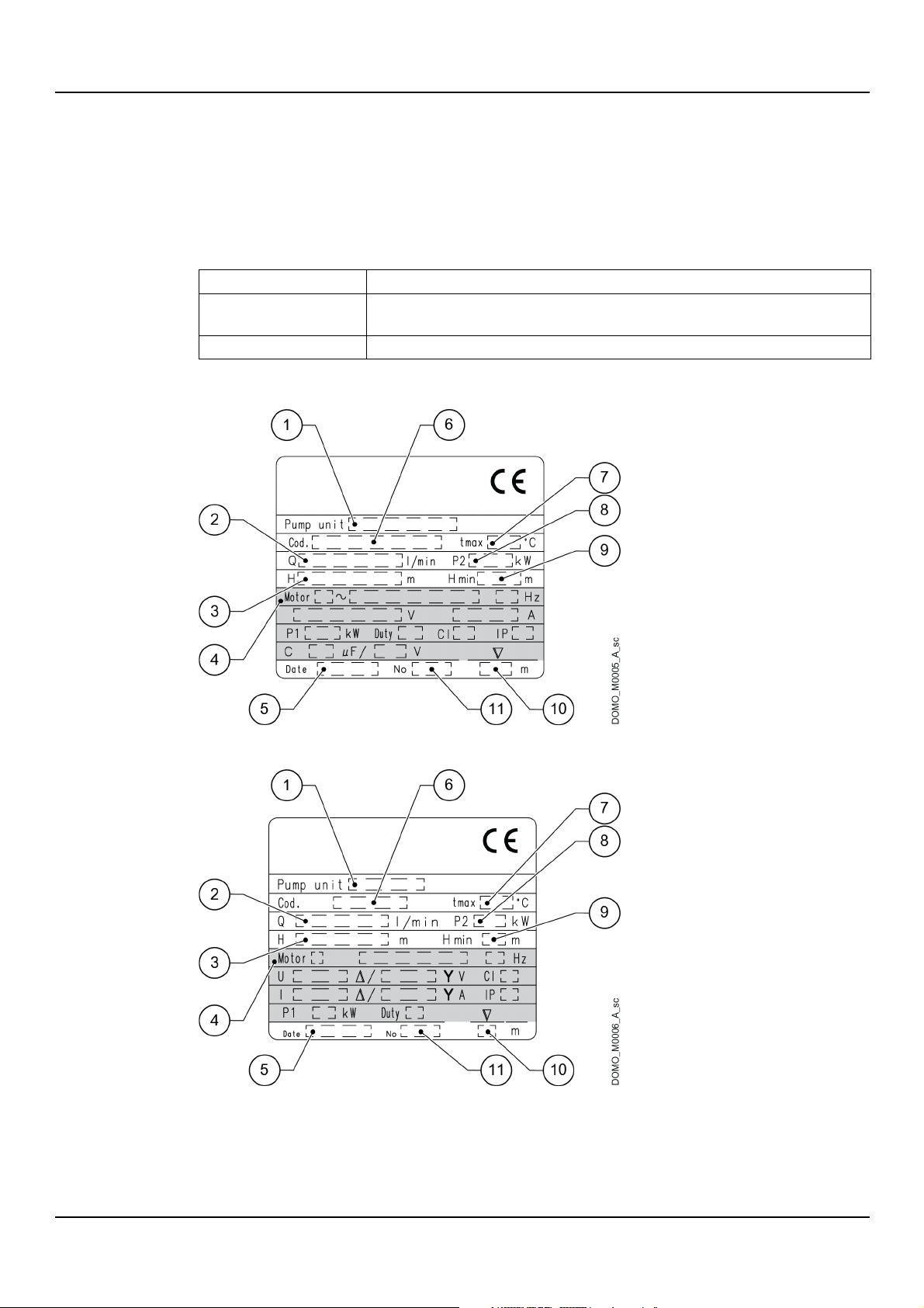
Figure 1: Single-phase
Figure 2: Three-phase
3.1 Designation
Submersible pump units for draining wastewater.
3.2 Denomination of the models
3.3 Data plate
en – Original instructions
DOMO, DOMO GRI - Installation, Operation and Maintenance Manual 9
Page 10
en – Original instructions
Position
number
Description
Position
number
Description
1 Model
7
Maximum liquid temperature
2 Flow rate range
8 Rated output
3 Head range
9 Minimum head
4 Motor data
10 Maximum immersion depth
5 Manufacturing date
11 Serial number
6 Pump unit code
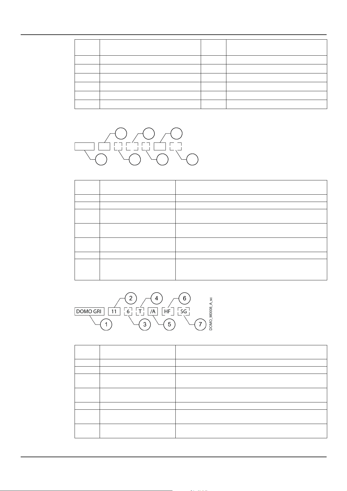
Figure 3: DOMO
Position
number
Description
Notes
1 Series name
2
Rated output
HP x 10
3 Frequency
Empty = 50 Hz
6 = 60 Hz
4 Impeller type
Empty = two-channel
VX = vortex
5 Phase
Empty = single phase
T = three-phase
6 Version
7 Float switch
Empty = with float
SG = without float
Figure 4: DOMO GRI
Position
number
Description
Notes
1 Series name
2
Rated output
HP x 10
3 Frequency
Empty = 50 Hz
6 = 60 Hz
4 Phase
Empty = single phase
T = three-phase
5 Version
HF = high flow rate
7 Float Empty = with float
SG = without float
DOMO_M0007_A_sc
3.4 Identification code
2 6
DOMO
10 TVX
6 /B GT
1
4
3 5 7
GT = with tube float
10 DOMO, DOMO GRI - Installation, Operation and Maintenance Manual
6
Flow
Empty = standard
Page 11
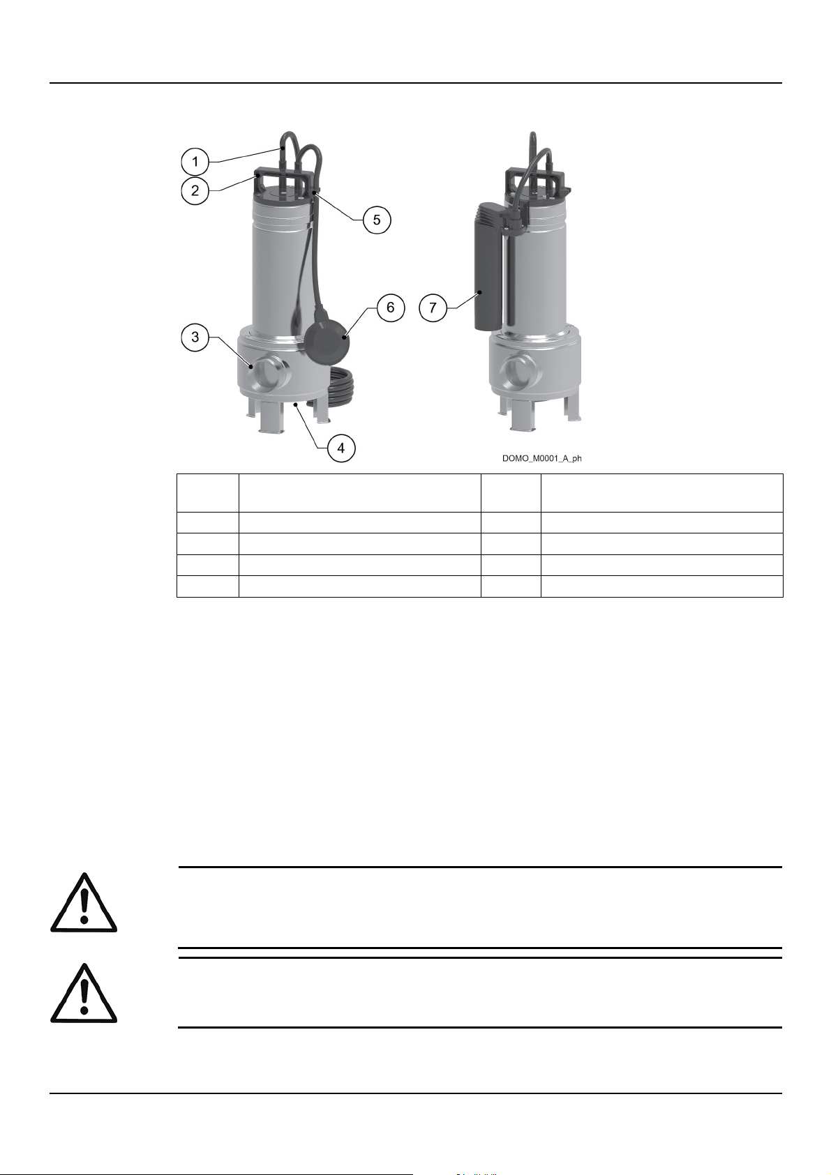
3.5 Names of the main components
Position
number
Description
Position
number
Description
1 Supply cord
5 Cable stop
2 Handle
6 Float 3 Discharge port
7 Tube float (DOMO GT)
4 Suction port
WARNING:
The unit was designed and built for the use described in the Intended Use section. Any other
uses are prohibited, as they could compromise the safety of the user and the efficiency of the
unit itself.
DANGER:
It is prohibited to use this
en – Original instructions
3.6 Intended use
Pumping of wastewater, including with a limited quantity of suspended filaments or solids.
Observe the operating limits in Technical Information on page 25.
Pumped liquids
• Clean water
• Wastewater and sewage water
• With suspended solids
• With suspended filaments
• Chemically and mechanically non aggressive
• Non flammable and/or explosive.
3.7 Improper use
unit to pump flammable and/or explosive liquids.
DOMO, DOMO GRI - Installation, Operation and Maintenance Manual 11
Page 12

en – Original instructions
DANGER: Potentially explosive atmosphere hazard
It is prohibited to start the unit in environments with potentially explosive atmospheres or with
combustible dusts
DANGER: Electrical hazard
Do
not use the unit in swimming pools or similar places when people are inside.
Examples of improper use
• Pumping liquids not compatible with the construction materials of the unit
• Pumping liquids with temperatures higher than what shown in Technical Information on
page 25
• Pumping hazardous, toxic, explosive, flammable or corrosive liquids
• Pumping sea water.
.
12 DOMO, DOMO GRI - Installation, Operation and Maintenance Manual
Page 13
4 Installation
DANGER:
All the hydraulic and electrical connections must be completed by a technician possessing the
technical
DANGER: Potentially explosive atmosphere hazard
It is prohibited to start the unit in environments with potentially explosive atmospheres or with
combustible dusts
WARNING:
Always wear personal protective equipment.
WARNING:
Always use
WARNING:
When selecting the place of installation and connecting the unit to the hydraulic and electric
power supplies, strictly comply with current regulations.
4.1 Precautions
Before starting, make sure that the safety instructions shown in Introduction and Safety on
page 4 have been fully read and understood.
-professional requirements outlined in the current regulations.
en – Original instructions
.
suitable working tools.
4.2 Mechanical installation
The unit may be used:
• with manual or automatic operation, for example connected to a level switch
• as mobile unit or in permanent installations, for example inside an existing tank or in a
prefabricated lifting station.
Dedicated installation kits and lifting stations are available: Contact Xylem or the Authorised
Distributor for further information.
4.2.1 Installation area
1. Follow the provisions in Operating environment on page 25.
2. Remove any solid sediments found.
3. If the unit is installed in a tank or a lifting station, check that their sizes are appropriate for
the unit and that the perimeter is even and without obstacles.
4. If the unit is fitted with a float, check that the tank or lifting station sizes do not impair the
free movement of the float.
DOMO, DOMO GRI - Installation, Operation and Maintenance Manual 13
Page 14
en – Original instructions
DANGER: Electrical hazard
Holding the unit by the
NOTICE:
In the operating position, the unit, the piping, the electric
must never be in contact with the walls of the tank.
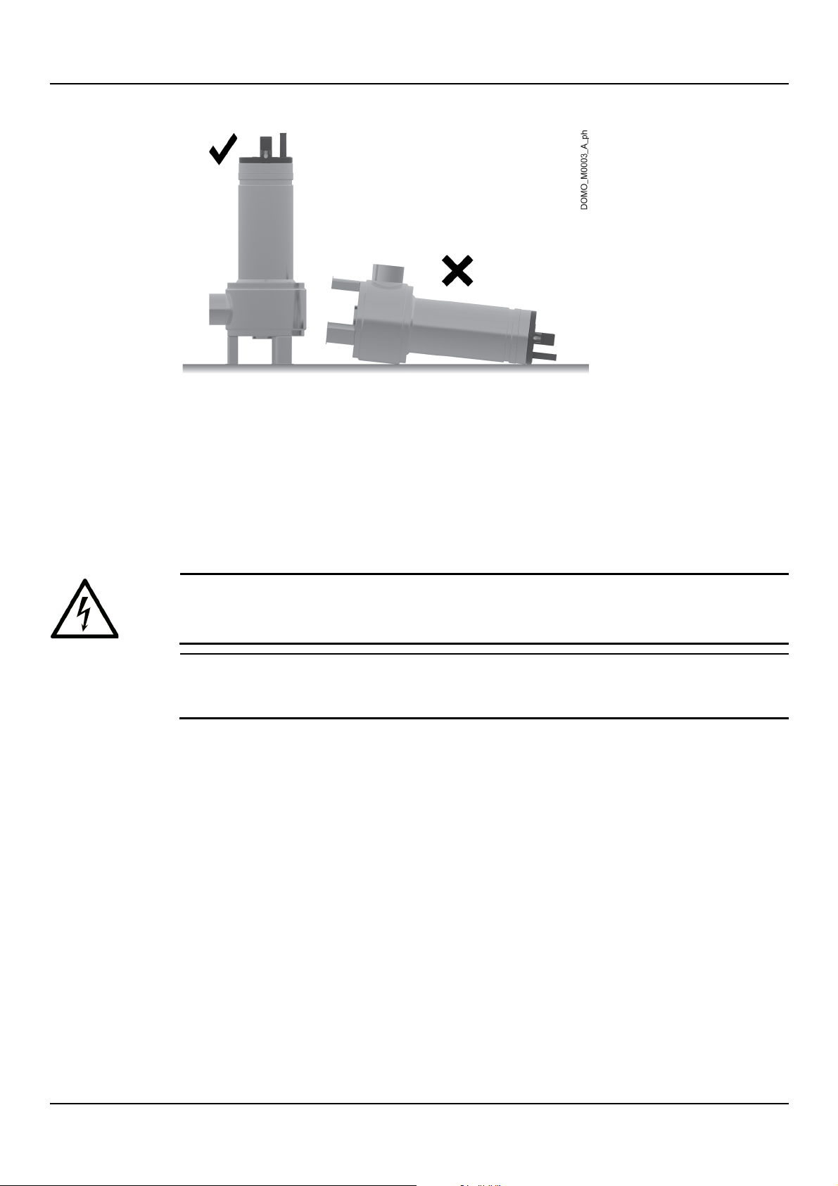
4.2.2 Permitted positions
4.2.3 Permanent installation on support base
1. Check that the bottom is solid, and if possible even.
2. Connect a 90° rigid or flexible elbow pipe to the discharge port (see Hydraulic connection
on page 17).
3. Submerge the unit in the liquid.
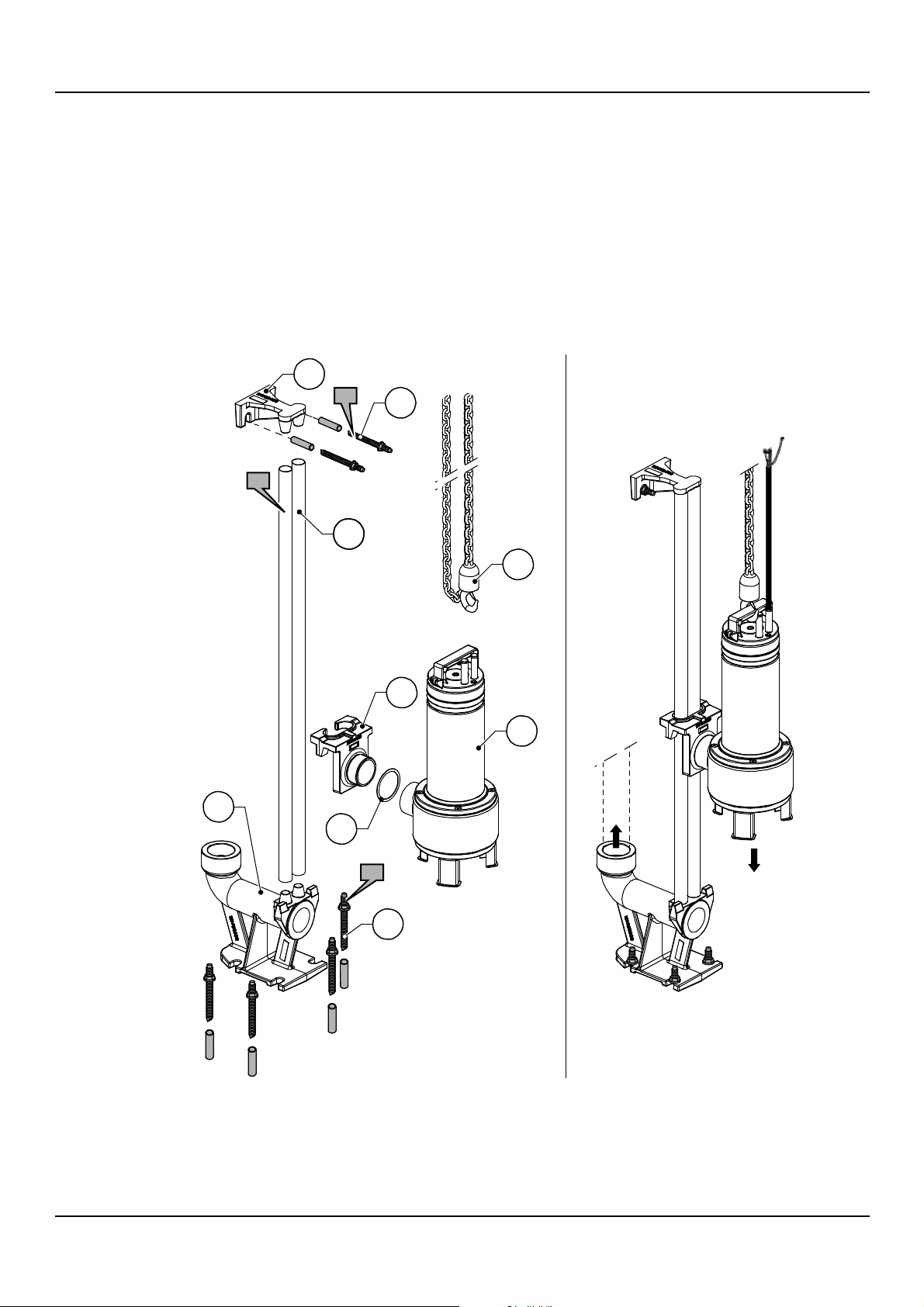
4.2.4 Permanent installation with quick coupling
The unit can be installed inside a tank or lifting station using the quick coupling descent kit
(optional).
supply cord or the float switch is strictly forbidden.
See the figure below.
1. Secure the guide pipe supports and the foot:
a) In case of tanks with loose or irregular bottom, install a solid foot base, as horizontal
and flat as possible.
b) Temporarily secure the pipe support to the edge of the tank using 2 dowels.
c) Place the foot at on the bottom, ascertaining the correct position with a plumb line,
using the tube support as reference.
d) Secure the foot to the bottom with 4 dowels.
e) Attach the discharge pipe to the foot (see Hydraulic connection on page 17).
2. Complete the installation of the kit:
a) Insert the guide tubes in the foot.
b) Cut the top ends of the pipes so that they coincide with the support.
c) Unscrew the pipe support.
d) Insert the sliding bracket in the pipes.
e) Insert the support at the top end of the pipes.
f) Permanently secure the support to the tank wall.
supply cord and the support chain
14 DOMO, DOMO GRI - Installation, Operation and Maintenance Manual
Page 15
en – Original instructions
DOMO_M0002_ A _de
3. DOMO GRI series only:
a) Remove one of the three support feet by unscrewing the M8x25 screw.
b) Re-tighten the screw.
Tightening torque: 13 Nm (115 lbf·in).
c) Repeat a) and b) for the other two feet.
4. Install the unit:
a) Screw the discharge port to the sliding bracket, placing the seal included in the kit
between the two.
b) Attach the chain to the handle.
c) Slide the sliding bracket through the guide pipes and lower the unit in the tank,
supporting it with the chain until the end.
d) Attach the end of the chain to the edge of the tank.
e) Secure the supply cord to the edge of the tank with a stop.
2
2x
7
2x
6
9
4
1
3
5
4x
8
DOMO, DOMO GRI - Installation, Operation and Maintenance Manual 15
Page 16
en – Original instructions
Position
number
Description
Position
number
Description
1 Unit 6 Corrosion resistant metal guide pipes, diameter
¾”, length exceeding the tank depth
2 Guide pipe support
7 Dowels
3 Foot 8 Dowels
4 Sliding bracket
9 Corrosion resistant metal chain, capacity 500 kg
(1100 lb), length exceeding the tank depth
5 O-ring
NOTICE:
The unit may only operate for a few minutes while only partially submerged in the liquid, for
example during emptying operations.
Series
Model
H1, mm (in)
H2, mm (in)
DOMO
7, 7VX
155 (6.1)
375 (14.8)
10, 10VX, 15, 15VX
155 (6.1)
420 (16.5)
DOMO GRI
11/A 129 (5)
394 (15.5)
11HF 131 (5.2)
396 (15.6)
15 149 (5.9)
414 (16.3)
4.3 Start and stop levels
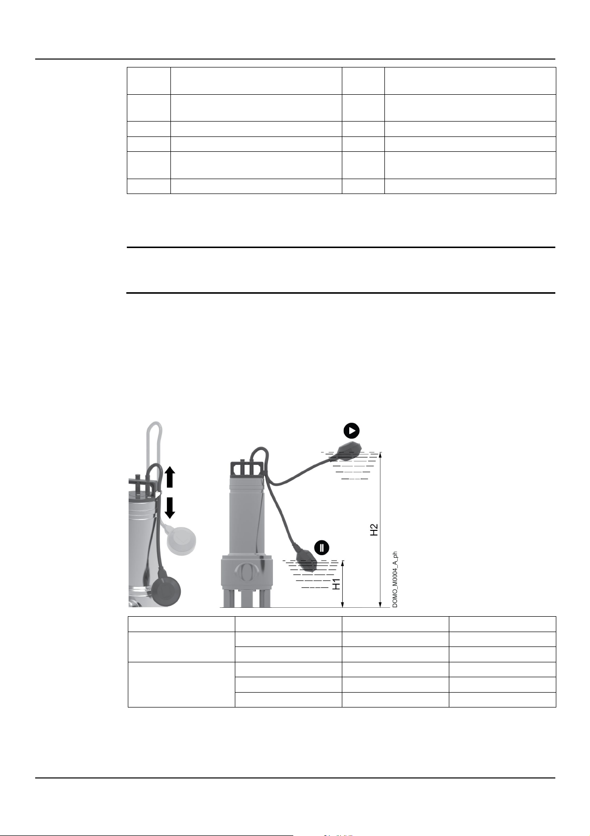
The float switch controls the start and stop of the unit (intermittent operation).
DOMO, DOMO VX, DOMO GRI
To adjust the level difference between start and stop, change the length of the float cable
using the cable stop found on the handle:
• Short cable: decrease the distance between minimum and maximum level, more frequent
starts and stops.
• Long cable: increase the distance between minimum and maximum level, less frequent
starts and stops.
The figure shows the minimum (H1) and the maximum (H2) permitted levels for operation
depending on the model.
16 DOMO, DOMO GRI - Installation, Operation and Maintenance Manual
Page 17
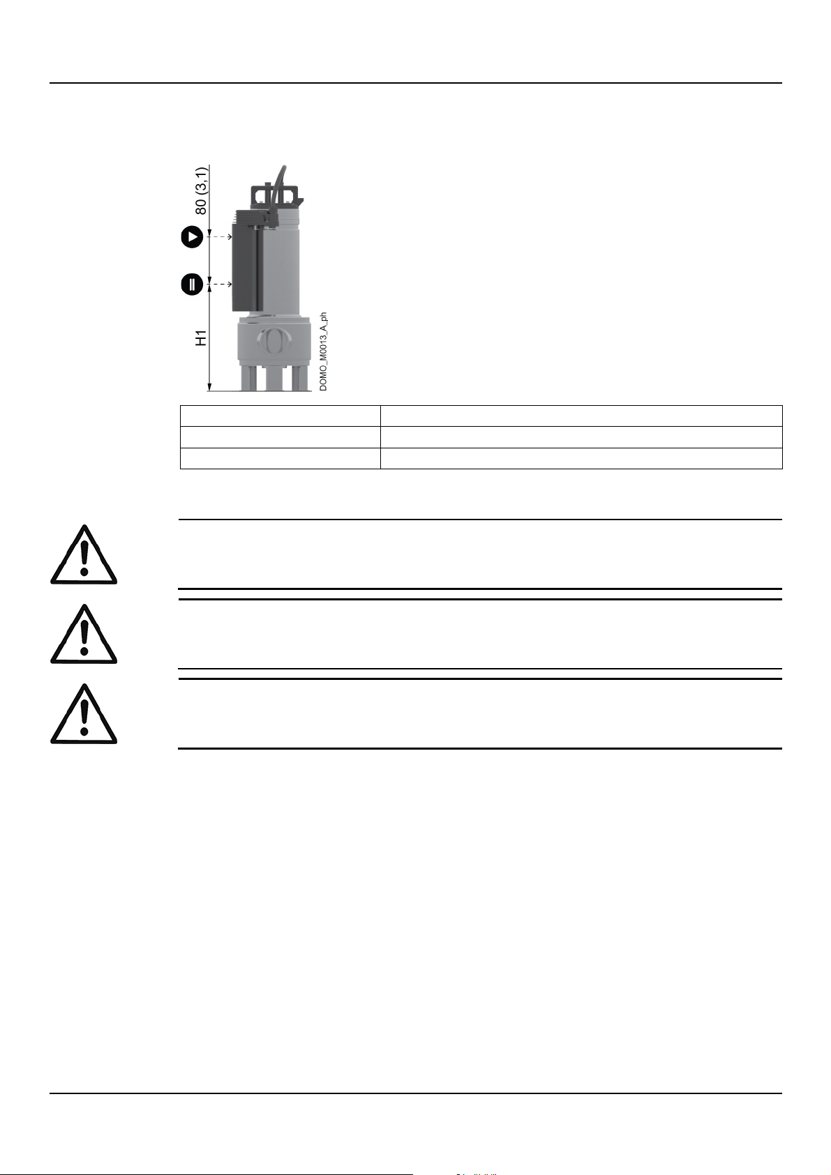
DOMO GT
Model
H1, mm (in)
7 GT, 7VX GT
225 (8.9)
10 GT, 10VX GT, 15 GT, 15VX GT
255 (10)
DANGER:
All the
technical
WARNING:
Piping must be sized to ensure safety at the maximum operating pressure.
WARNING:
Install appropriate seals between the unit couplings and the pipings.
en – Original instructions
The level difference between start and stop cannot be adjusted.
The figure shows the minimum permitted level for operation (H1) depending on the model.
4.4 Hydraulic connection
hydraulic and electrical connections must be completed by a technician possessing the
-professional requirements outlined in the current regulations.
4.4.1 Guidelines for the hydraulic system
1. Attach the piping, rigid or flexible, to the discharge port.
2. Support the piping independently to prevent it from weighing on the unit.
3. Install a check valve on the piping, at least 1 m (3.3 ft) from the discharge port.
4. Install a gate valve downstream the check valve.
5. For units without float to be used for automatic operation, install a device stopping the unit
when the liquid level reaches the minimum permitted limit, see Start and stop levels on
page 16.
The figure shows a typical installation.
DOMO, DOMO GRI - Installation, Operation and Maintenance Manual 17
Page 18
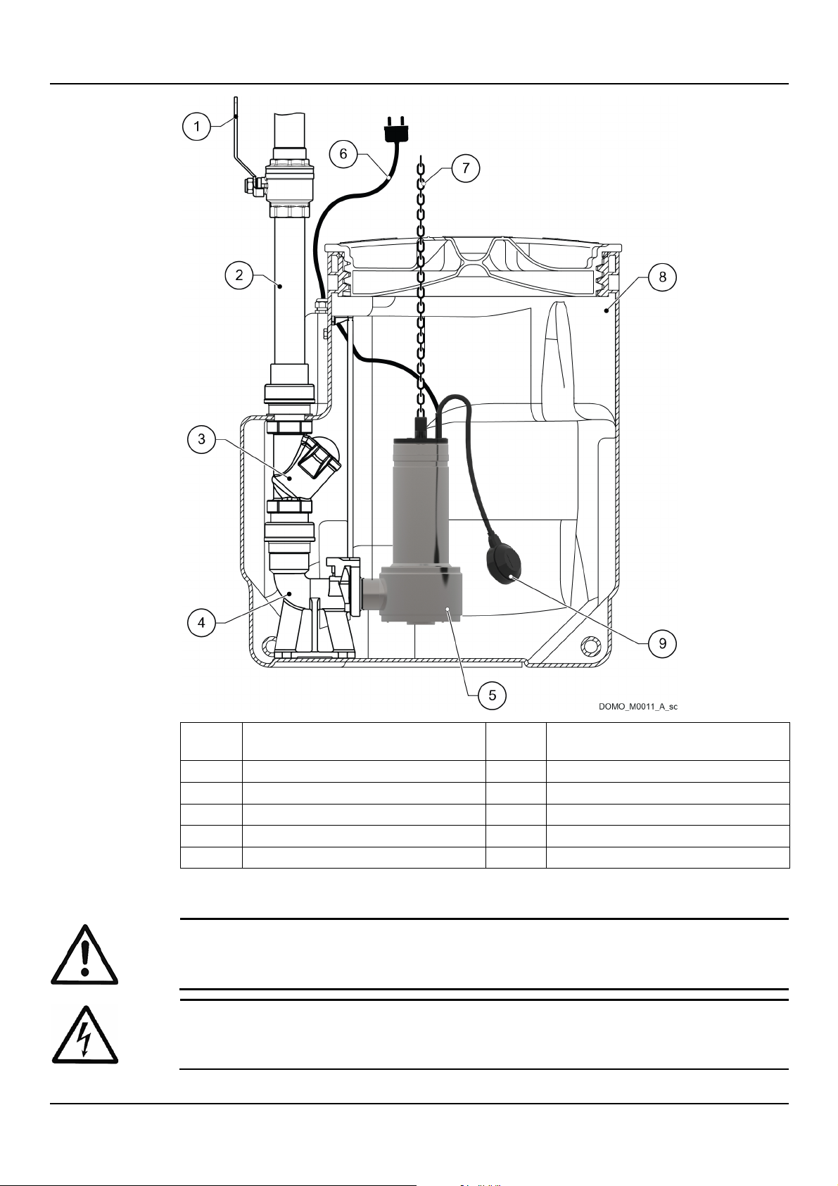
en – Original instructions
Position
number
Description
Position
number
Description
1 Gate valve
6 Electric supply cord
2 Discharge pipe
7 Chain
3
Check valve
8 Tank 4 Descent kit
9 Float 5 Unit
DANGER:
All the hydraulic and electrical connections must be completed by a technician possessing the
technical
DANGER: Electrical hazard
Before starting work, check that the unit is unplugged and that the pump unit, the control
panel and the auxiliary control circuit cannot restart, even unintentionally.
4.5 Electrical connection
-professional requirements outlined in the current regulations.
18 DOMO, DOMO GRI - Installation, Operation and Maintenance Manual
Page 19
4.5.1 Ground
DANGER: Electrical hazard
Always connect the
attempting to make any other electrical connections.
DANGER: Electrical hazard
Connect the pump
(ground).
DANGER: Electrical hazard
Check that the external protection conductor (ground) is longer than the phase conductors; In
case of accidental disconnection of the unit from
conductor must be the last one to detach itself from the terminal.
DANGER: Electrical hazard
Install suitable systems for protection against indirect contact, in order to prevent lethal electric
shocks.
NOTICE:
The electric panel must match the ratings on the unit data plate. Improper combinations could
damage the motor.
Motor
Safety features
Single-phase
• Automatic reset thermal-ampere protection, in-built (motor protector)
with C curve and Icn ≥ 4.5 kA, or other similar device.
Three-phase
•
with C curve and Icn ≥ 4.5 kA, or other similar device.
en – Original instructions
external protection conductor (ground) to the ground terminal before
unit and any electric accessories to a socket with protection conductor
4.5.2 Guidelines for electrical connection
1. Check that:
• The mains voltage and frequency match the specifications on the data plate
• The supply cord is protected from high temperatures, vibrations, collisions and
abrasions.
2. Check that the power supply line is provided with:
• a short circuit protection device of appropriate size
• a mains disconnection device with contact opening distance ensuring complete
disconnection for overvoltage III category conditions
• an RCCB earth leakage switch with tripping current < 30 mA.
4.5.3 Guidelines for the control electric panel
the phase conductors, the protection
• Install appropriate devices for protecting the motor from overloads and short circuits:
• From short circuit, by the installer: aM fuses (motor start-up), or thermal magnetic switch
Thermal, by the installer: trip class 10 A overload thermal relay + aM fuses (motor startup), or start class 10 A motor protection thermal magnetic switch
• From short circuit, by the installer: aM fuses (motor start-up), or thermal magnetic switch
• If required, install phase failure sensitive thermal relays.
Motor protection from overtemperature
• Single-phase: the unit is equipped with built-in capacitor and thermal overload protection,
and stops automatically in case of overtemperature. After 2-4 minutes the thermal overload
protection gives the restart consent.
• Three-phase: Install an appropriate motor protector with D curve in the control panel, in
accordance with the current shown in the data plate.
DOMO, DOMO GRI - Installation, Operation and Maintenance Manual 19
Page 20
en – Original instructions
DANGER: Electrical hazard
Do not use the unit in swimming pools or similar places when people are inside.
WARNING: Electrical hazard
Check that the unit is properly connected to the mains power supply.
DANGER: Injuries hazard
Do not insert your hands at the
caused by moving components.
WARNING: Injuries hazard
The unit, equipped with a single
protection, could restart inadvertently after it
WARNING:
It is prohibited to put combustible materials near the unit.
WARNING:
Do not hold the unit by the handle during operation.
WARNING:
Make sure that the drained liquid cannot cause damage or
NOTICE:
In case of outdoor use, the length of the supply cord must exceed 10 m (33 ft).
NOTICE:
Dry run of the unit is forbidden.
NOTICE:
Make sure that the suction port is completely submerged in the liquid before start-up.
NOTICE:
The unit may only operate for a few minutes while only partially submerged in the liquid, for
example during emptying operations.
5 Use and operation
5.1 Precautions
bottom of the unit when in operation: risk of personal injury
-phase motor with automatic reset thermal overload
has cooled down: risk of physical injury.
injuries.
See Mechanical characteristics on page 26.
20 DOMO, DOMO GRI - Installation, Operation and Maintenance Manual
Page 21
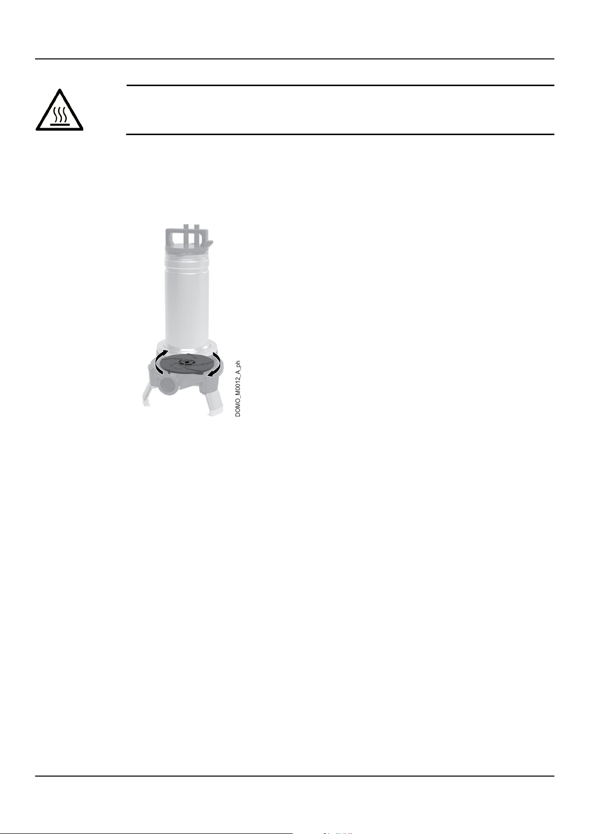
If during the operation the unit is partially uncovered:
WARNING:
Be aware of the
extreme heat generated by the unit.
5.2 Rotation direction check (three-phase motors)
1. Place the unit in the vertical position on a level and flat surface.
2. Looking at the unit from the top, start and then stop it immediately: the rotation direction is
correct if the unit impulse movement at start-up tends to turn it clockwise. This means that
the motor is turning clockwise as it should.
en – Original instructions
5.3 Starting and stopping
Float switch version
1. Connect the plug to the mains and/or turn on the switch: depending on the position of the
float, the unit stays idle or starts to operate.
2. With the unit in operation, check that:
• No liquid is leaking from the pipes
• There is no unwanted noise or vibrations
• There are no vortexes nearby the suction port
• Liquid is actually being pumped.
3. When the float reaches the low position (minimum liquid level), the pump automatically
stops.
Version without float switch
1. Connect the plug to the mains and/or turn on the switch: the unit starts.
2. With the unit in operation, complete the same checks as for the float version.
3. Once the unit has taken up liquid to the minimum level, disconnect the plug from the mains
and/or turn off the switch to switch it off.
DOMO, DOMO GRI - Installation, Operation and Maintenance Manual 21
Page 22
en – Original instructions
WARNING:
Maintenance must be done by a technician possessing the technical-professional requirements
outlined in the current regulations.
WARNING:
Always wear personal protective
WARNING:
Always use suitable working tools.
DANGER: Electrical hazard
Before starting work, check that the unit is unplugged and that the pump unit, the control
panel and the auxiliary control circuit cannot restart, even unintentionally
6 Maintenance
6.1 Precautions
Before starting, make sure that the instructions shown in Introduction and Safety on page 4
have been fully read and understood.
equipment.
6.2 Maintenance every 6 months of operation
1. Check the integrity of the supply cord; if the cable is damaged contact Xylem or the
Authorised Distributor for its replacement.
2. Carefully clean the unit, particularly near the suction port.
6.3 Long periods of inactivity
1. Rinse the unit with soft water.
2. Empty the unit and the piping.
3. Put the unit out of service.
4. Protect the unit against freezing.
6.4 Spare parts ordering
Identify the spare parts with the product codes directly on the site www.lowara.com/spark.
Contact Xylem or the Authorised Distributor for technical information.
.
22 DOMO, DOMO GRI - Installation, Operation and Maintenance Manual
Page 23
7 Troubleshooting
WARNING:
Maintenance must be done by a technician possessing the technical-professional requirements
outlined in the current
WARNING:
Observe the safety requirements in the chapters on Use and Operation and Maintenance.
WARNING:
If a fault cannot be corrected or is not mentioned, contact Xylem or the Authorised Distributor.
Cause
Remedy
Power supply cut off
Restore the power supply
Float low
Adjust the float
Fuses blown
Replace fuses
The thermal overload protection of the motor has been
•
Disconnect the electric power supply and wait 2 minutes
before reconnecting it.
Supply cord is damaged
Contact Xylem or the Authorised Distributor for the
replacement
Control panel faulty
Check and repair or replace the control panel
Cause
Remedy
High liquid temperature
Contact Xylem or the Authorised Distributor
overload)
It is calibrated at a value too low in relation to the rated
current of the motor
Recalibrate
Input voltage outside the rated limits
Make sure the voltage values are correct
Unbalanced input voltage
Make sure the voltage of the three phases is balanced
Wrong working curve (flow rate below or above the
permitted limits)
Bring the flow rate back within the permitted limits
Impeller seized
Contact Xylem or the Authorised Distributor
Motor turns in the wrong direction
Check the direction of rotation and change it if necessary
Motor or cable short circuit
Contact Xylem or the Authorised Distributor
7.1 Precautions
regulations.
7.2 The unit does not start
en – Original instructions
triggered
• Check the liquid level, and/or
•
7.3 The thermal overload protection triggers
Presence of solid or fibrous substances in the liquid (unit
Remove the substances
Reset the thermal overload protection on the control
panel, and/or
DOMO, DOMO GRI - Installation, Operation and Maintenance Manual 23
Page 24

en – Original instructions
Cause
Remedy
Tank liquid level too low
•
• Adjust the float
Foreign bodies in the unit
Remove the foreign bodies
Discharge pipe throttled
Remove the throttling
Piping and/or unit clogged
Remove the clogging
Undersized unit
Contact Xylem or the Authorised Distributor
Cause
Remedy
Motor turns in the wrong direction
Check the direction of rotation and change it if necessary
Float not adjusted correctly
Adjust the float
The float cannot move freely
Release the float
Float faulty
Contact Xylem or the Authorised Distributor
Undersized unit
Contact Xylem or the Authorised Distributor
Impeller worn
Contact Xylem or the Authorised Distributor
7.4 The unit runs but there is little or no flow rate
7.5 The unit never stops
Increase the installation depth, and/or
24 DOMO, DOMO GRI - Installation, Operation and Maintenance Manual
Page 25

8 Technical Information
Applications
DOMO
DOMO VX
DOMO GRI
Drainage of flooded areas
• • •
Lowering of the underground water level
• • •
Draining wells
• • •
Emptying of rain water wells storing rain water from rooftops
and gutters
• • •
Emptying of tanks and other containers
• • •
treatment systems
• • •
Pumping of grey wastewater not from toilets
• • •
Pumping of grey wastewater from toilets
• • •
Pumping of wastewater or sewage water with suspended
filaments
•
•
Movement of wastewater or sewage water in pressurized
systems
•
Pumping wastewater or sewage water with suspended solids
•
NOTICE:
If the temperature exceeds the stated limits, contact Xylem or the Authorised Distributor.
Series
Model
Maximum diameter, mm (in)
DOMO
7, S7, 7VX, S7VX
≤ 35 (1.4)
10, 15, 20, 10VX, 15VX, 20VX
≤ 50 (2)
DOMO GRI
All -
8.1 Applications
Pumping of domestic waste from sewage well or slurry
en – Original instructions
8.2 Operating environment
Non-aggressive, non-explosive atmosphere, and not subjected to frost.
Temperature of pumped liquid
0 to 35°C (32 to 95°F).
Liquid pH
4 to 10.
Liquid density
≤ 1100 kg/m³ (9.2 lb/gal).
Liquid viscosity
≤ 10 mm²/s (10 cSt).
Suspended impurities
DOMO, DOMO GRI - Installation, Operation and Maintenance Manual 25
Page 26
en – Original instructions
Series
Model
Head, m (ft)
DOMO
7CG, S7CG, 7T, S7T
10.7 (35)
10CG, 10T
10.1 (33)
15CG, 15T
12.7 (42)
20T 14.8 (49)
7VXCG, S7VXCG, 15VXCG, 7VXT, S7VXT, 15VXT
9.1 (30)
10VXCG, 10VXT
7.7 (25)
20VXT
11 (36)
DOMO GRI
11/A, 11T/A
25 (82)
11HF, 11T HF
16.7 (55)
15, 15T
29.0 (95)
Series
Model
Head, m (ft)
DOMO
S76CG, S76T
10.5 (34)
106CG, 106T
8.8 (29)
156CG, 156T
12.4 (41)
206T 14.5 (48)
S76VXCG, S76VXT
8 (26)
106VXCG, 106VXT
7.4 (24)
156VXCG, 156VXT
10 (33)
206VXT
11.8 (39)
DOMO GRI
116T 28.9 (95)
NOTICE:
Make sure that the suction port is completely submerged in the liquid before start-up.
Series
Model
Version
Minimum level of the unit
support base, mm (in)
CG SG GT T
DOMO
7, S7
• • • •
55 (2.2)
10, 15, 20
• • • •
70 (2.8)
7VX, S7VX
•
• •
90 (3.5)
10VX, 15VX, 20VX
•
• •
115 (4.5)
DOMO GRI
11, 15
•
• •
110 (4.3)
8.3 Maximum head
50 Hz
60 Hz
8.4 Maximum number of starts per hour
25.
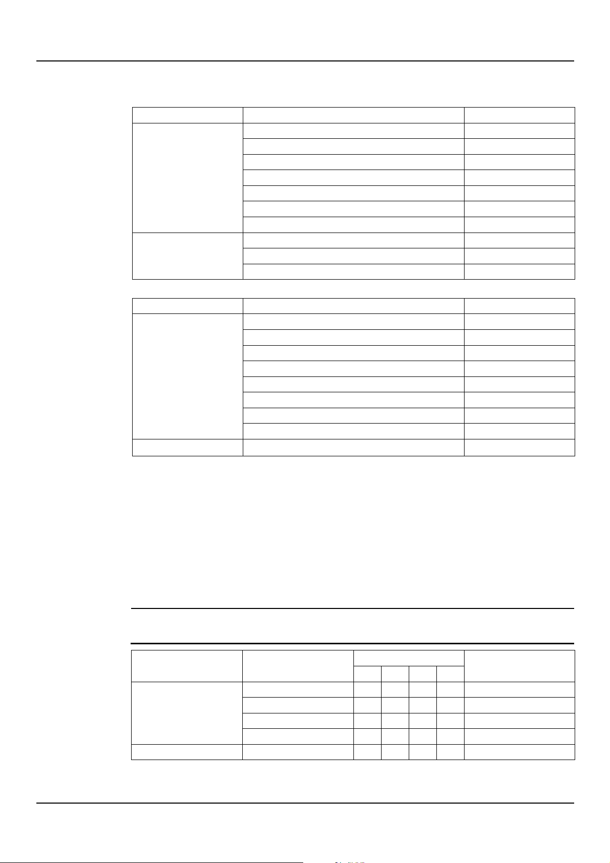
8.5 Mechanical characteristics
Electric supply cord length
10 m (33 ft)
DOMO S7: 5 m (16 ft), 10 m (33 ft) on request.
Minimum pumped liquid level
26 DOMO, DOMO GRI - Installation, Operation and Maintenance Manual
Page 27
Maximum immersion depth
NOTICE:
The supply cord must be at least 3 m (10 ft) out of the liquid.
Frequency Hz
Phase ~
No. of conductors + earth
UN, V ± %
50
1 2 + 1 220-240 ± 6
3 3 + 1 230/400 ± 10
60
1 2 + 1 220-230 ± 6
3 3 + 1 220/380 ± 5
Unit position
LpA sound pressure level measured in free field at a distance of one metre, dB ± 2
Submerged
Non-applicable
Partially submerged
< 70
Figure 5: DOMO
5 m (16 ft)
Protection class
IPX8.
8.6 Electrical specifications
Permitted tolerances for the supply voltage
8.7 Sound pressure
en – Original instructions
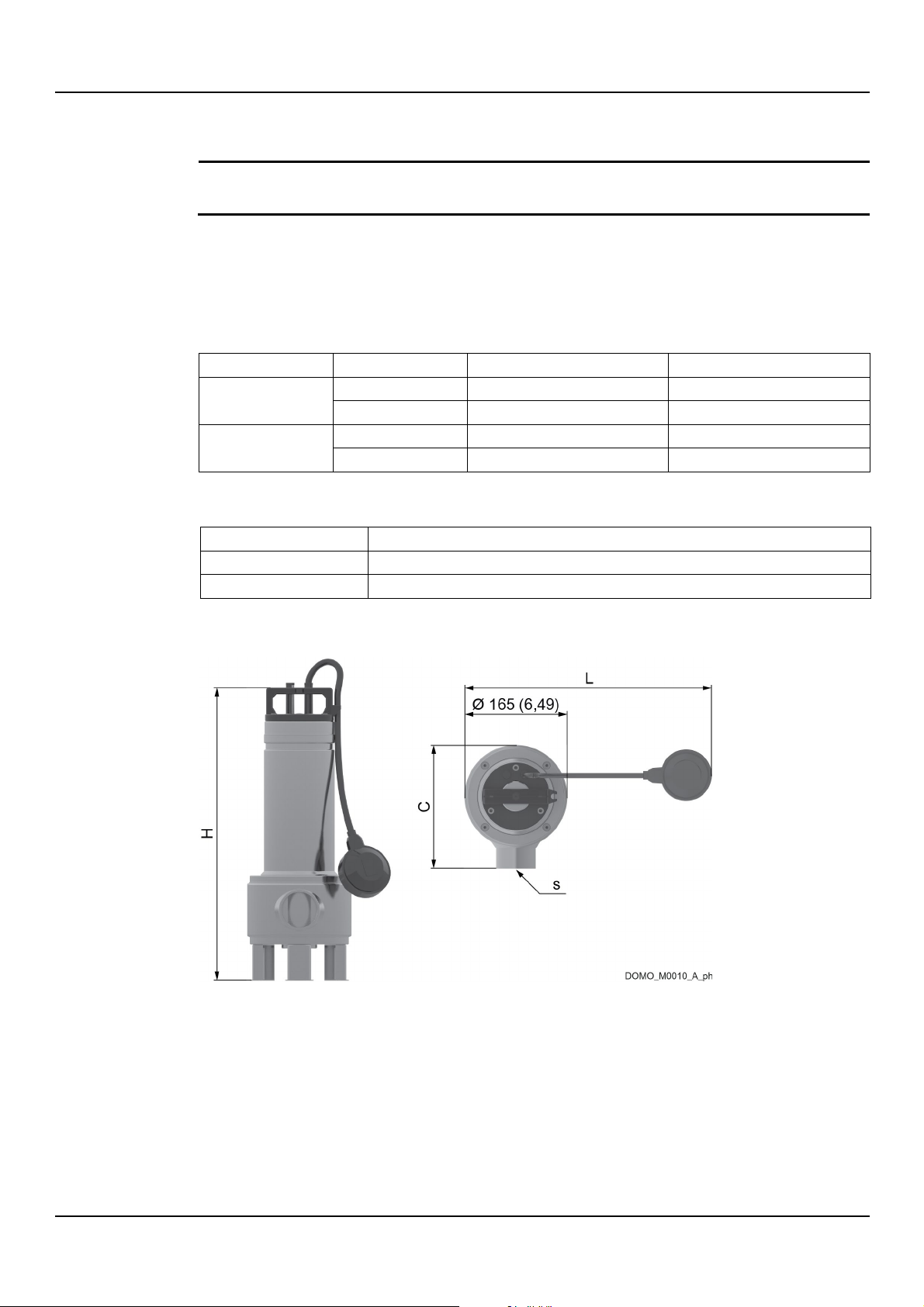
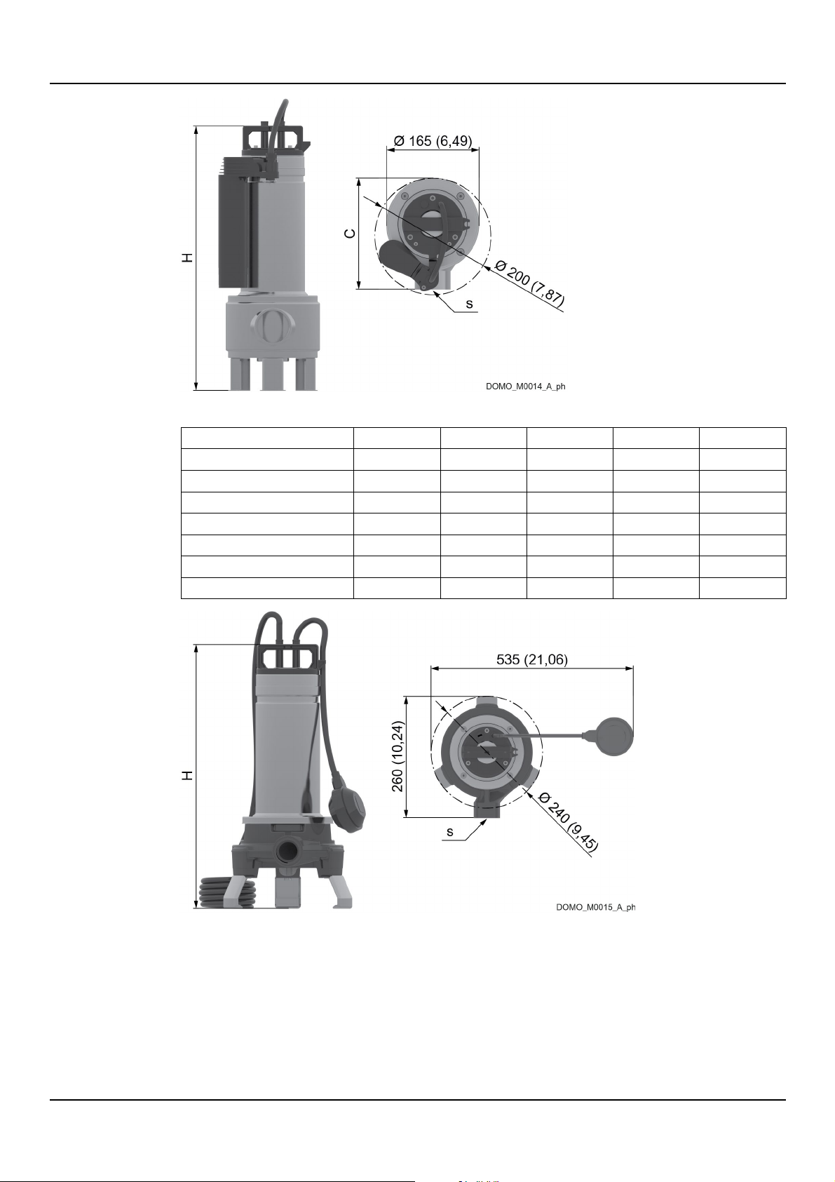
8.8 Dimensions and weights
DOMO, DOMO GRI - Installation, Operation and Maintenance Manual 27
Page 28
en – Original instructions
Figure 6: DOMO GT
Model
H, mm (in)
C, mm (in)
L, mm (in)
s, in Weight, kg (lb)
7, 7VX, 7 GT, 7VX GT
391 (15.39)
193 (7.59)
420 (16.53)
Rp 1 ½
10.2 (22.5)
7T, 7VXT
391 (15.39)
193 (7.59)
- Rp 1 ½
8.9 (19.6)
10, 10VX, 10 GT, 10VX GT
468 (18.43)
198 (7.79)
495 (19.49)
Rp 2 13.6 (30)
10T, 10VXT
438 (17.24)
198 (7.79)
- Rp 2 11.6 (25.6)
15, 15VX, 15 GT, 15VX GT
468 (18.43)
198 (7.79)
495 (19.49)
Rp 2 15.3 (33.7)
15T, 15VXT
468 (18.43)
198 (7.79)
- Rp 2 13.6 (30)
20T, 20VXT
468 (18.43)
198 (7.79)
- Rp 2 14.6 (32.2)
Figure 7: DOMO GRI
28 DOMO, DOMO GRI - Installation, Operation and Maintenance Manual
Page 29

Model
H, mm (in)
s, in Weight, kg (lb)
GRI 11/A
442 (17.40)
Rp 1 20.8 (46)
GRI 11/A SG
442 (17.40)
Rp 1 20.6 (45)
GRI 11T/A
442 (17.40)
Rp 1 20.1 (44)
GRI 11HF
444 (17.48)
Rp 1 ¼
20.8 (46)
GRI 11HF SG
444 (17.48)
Rp 1 ¼
20.6 (45)
GRI 11T HF
444 (17.48)
Rp 1 ¼
20.1 (44)
GRI 15
462 (18.19)
Rp 1 ¼
23 (51)
GRI 15 SG
462 (18.19)
Rp 1 ¼
22.8 (50)
GRI 15T
442 (17.40)
Rp 1 ¼
22.3 (49)
en – Original instructions
DOMO, DOMO GRI - Installation, Operation and Maintenance Manual 29
Page 30

en – Original instructions
WARNING:
The unit must be
different types of materials (steel, copper, plastic, etc.).
WARNING:
It is prohibited to dispose of lubricating fluids and other hazardous substances in the
environment.
9 Disposal
9.1 Precautions
disposed of through approved companies specialised in the identification of
30 DOMO, DOMO GRI - Installation, Operation and Maintenance Manual
Page 31

10 Declarations
Montecchio Maggiore, 12/06/2018
rev.01
Signed for and on behalf of: Xylem Service Italia S.r.l.
Montecchio Maggiore, 12/06/2018
10.1 EC Declaration of Conformity (Original)
Xylem Service Italia S.r.l., with headquarters at Via Vittorio Lombardi 14 - 36075 Montecchio
Maggiore VI - Italy, hereby declares that the product:
Pump unit (see the label on the Safety and Other Information manual)
fulfils the relevant provisions of the following European Directive:
• Machinery 2006/42/EC (ANNEX II - natural or legal person authorised to compile the
technical file: Xylem Service Italia S.r.l. - Via Vittorio Lombardi 14 36075 Montecchio
Maggiore VI - Italy)
and the following technical standards:
EN 809:1998+A1:2009, EN 60335-1:2012+A11:2014,
EN 60335-2-41:2003+A1:2004+A2:2010
Amedeo Valente
(Director of Engineering and R&D)
1
, EN 62233:2008
en – Original instructions
10.2 EU Declaration of Conformity (n. EMCD30)
1. Apparatus model/Product:
see the label on the Safety and Other Information manual
2. Name and address of the manufacturer:
Xylem Service Italia S.r.l.
Via Vittorio Lombardi 14
36075 Montecchio Maggiore VI
Italy
3. This declaration of conformity is issued under the sole responsibility of the manufacturer.
4. Object of the declaration:
Pump unit
5. The object of the declaration described above is in conformity with the relevant Union
harmonization legislation:
2014/30/EU Directive of 26 February 2014 (electromagnetic compatibility)
6. References to the relevant harmonized standards used or references to the other technical
specifications, in relation to which conformity is declared:
EN 61000-6-1:2007, EN 61000-6-3:2007+A1:2011
7. Notified body: -
8. Additional information: -
Amedeo Valente
(Director of Engineering and R&D)
rev.01
Lowara is a trademark of Xylem Inc. or one of its subsidiaries.
1
Except section 25.8 for models with supply cords of less than 10 m (33 ft)
DOMO, DOMO GRI - Installation, Operation and Maintenance Manual 31
Page 32

en – Original instructions
11 Warranty
11.1 Information
For information on the warranty refer to the documentation of the sale contract.
32 DOMO, DOMO GRI - Installation, Operation and Maintenance Manual
Page 33

en – Original instructions
DOMO, DOMO GRI - Installation, Operation and Maintenance Manual 33
Page 34

Xylem |’zīləm|
1) The tissue in plants that brings water upward from the roots;
2) A leading global water technology company.
We’re a global team unified in a common purpose: creating innovative solutions to
meet our world’s water needs. Developing new technologies that will improve the
way water is used, conserved, and re
move, treat
water efficiently, in their homes, buildings, factories and farms. In more than 150
countries, we have strong, long
for our powerful combination of leading product brands and applications expertise,
backed by a legacy of innovation.
For more information on how Xylem can help you, go to www.xylem.com
-used in the future is central to our work. We
, analyze, and return water to the environment, and we help people use
-standing relationships with customers who know us
Xylem Service Italia S.r.l.
Via Vittorio Lombardi 14
36075 – Montecchio Maggiore (VI) - Italy
www.xylem.com/brands/lowara
Lowara is a trademark of Xylem Inc. or one of its subsidiaries.
© 2019 Xylem, Inc. Cod.001082034EN rev.A ed.01/2019
 Loading...