

Page 1

I154GB06
04
DMK40 DATA-LOGGER
SOFTWARE MANUAL
INDEX
Introduction ............................................................................................................................................ 2
Minimum resources of the PC........................................................................................................................ 2
Installation ............................................................................................................................................ 2
Activation of the PC - DMK connection ..................................................................................................... 3
Connection diagram (direct) ....................................................................................................................... 3
Basic principles ............................................................................................................................................ 5
Main window ............................................................................................................................................ 5
System configuration...................................................................................................................................... 6
Important note: ......................................................................................................................................... 9
Display menu .......................................................................................................................................... 10
Data collection............................................................................................................................................ 10
Graphs .......................................................................................................................................... 11
Front panel .......................................................................................................................................... 14
Password .......................................................................................................................................... 14
Communication menu................................................................................................................................... 15
Online .......................................................................................................................................................... 15
Offline.......................................................................................................................................................... 15
Modem Call ................................................................................................................................................. 15
Hang up....................................................................................................................................................... 16
Parameters menu .......................................................................................................................................... 17
Basic setup ................................................................................................................................................ 17
Capacitor overload setup.......................................................................................................................... 18
Save-Load-Print.......................................................................................................................................... 18
APPENDIX A – Connection modes .............................................................................................................. 19
Connection via standard modem ......................................................................................................... 19
Code: MSGB202$0500.doc 18/06/2004 P. 1 / 20
Page 2

Introduction
Using the DMK40 series multimeter data setting and acquisition software, you can:
• Set the measurements to be sampled according to sampling time.
• Display the data unloaded by the DMK40 in MS-Access format.
• Display the measurements in graphic format.
• Convert the MS-Access tables acquired by the DMK40 multimeter in ASCII or MS-Excel text format.
• Plot graphs of the measurements sampled.
• Display a ‘virtual’ representation of the front panel of the multimeter with the possibility of accessing all
the measurements and of activating the buttons.
• Display and modify the set-up parameters of the multimeter with the possibility of saving the settings on
disk, of recalling and printing these.
• Change the language of the program menus and commands selecting either Italian or English.
Minimum resources of the PC
• Windows
• Graphic card with a minimum resolution of 800x600; 1024x768 or higher is recommended
• A free standard RS232 serial interface (COM:)
• 64Mb of RAM
• Pentium
• CD-ROM drive for installation
®
95/98/2000 operating system
®
class or higher processor
Installation
For installation, you need a PC with the operating system already installed and running and the program
setup CD. You should also have at least a basic knowledge of the PC and be familiar with Windows
operating system commands.
The software is delivered on a CD with two different installation procedures. The standard installation
procedure used with the first releases of the Win 95 and 98 operating systems is held in the Setup1
directory. The Setup2 directory contains a new installation procedure for the latest releases of the Win 98
operating system and for Win 2000.
Setup1:
1. Close all applications running
2. Insert the CD in the drive
3. From the Setup1 directory, start the Setup.exe program
4. Press the button with the PC icon to start the installation procedure.
5. A window is displayed asking you to specify the directory in which you want to install the program. To
change directory, enter the new name in the specific box.
6. Follow the instructions provided. If a message is displayed indicating that there are more recent files
present on the PC than those being installed, maintain the files already present (answer YES or ‘keep’ to
the prompt)
Setup2:
1. Close all applications running
2. Insert the CD in the drive
3. From Setup2 directory, start the Dmk.msi program
4. If your PC does not recognize the .msi (microsoft installer) files, start the InstMsiA.exe program and
then go back to point 3.
5. A window is displayed asking you to specify the directory in which you want to install the program. To
change the directory, enter the new name in the specific box.
1. If rebooting of the system is requested following installation, carry out the procedure
®
Code: MSGB202$0500.doc 18/06/2004 P. 2 / 20
Page 3
Activation of the PC - DMK connection
To run the program, the PC and the DMK multimeters must be able to exchange data on the serial link. To
activate the connection, carry out the following operations:
1. Make sure that the PC you intend to use has an available and free RS-232 serial interface port. The
serial ports are usually identified with the COM: code and usually range from COM1: to COM4: even
though most of the PCs available on the market have only two serial ports (COM1: and COM2:) which
can be identified by their 9-pin male receptacle connector. To use the program, you must first of all
identify which port of your PC you intend to use; remember that, in some cases, one of the serial ports
may already be occupied by the mouse
2. Configure the software for use of the port selected; you can do this during the initial installation phase or
subsequently using the Configuration-Options-General menu (see the specific paragraph). The default
serial port is COM1: set to 9600 baud, no parity.
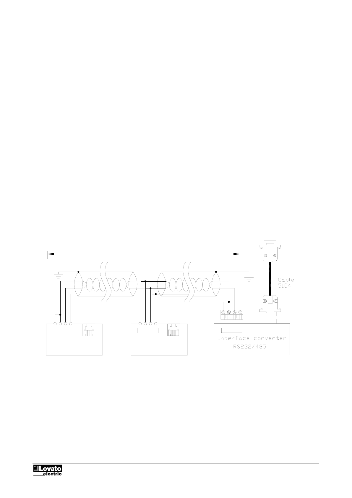
3. Set up the RS-485 network, i.e. connect the Rs232/Rs485 converter to the PC and then all the
multimeters to each other and to the converter as indicated in the Connection diagrams paragraph
below. Comply scrupulously with the polarity of the Rs485 cables.
4. We recommend use of a Rs232/Rs485 converter furnished by Lovato. If you intend to use another type
of converter, Lovato will be unable to provide assistance in the case of wiring problems and to assure
correct functioning of the 485 network. In any case, the converter must be insulated and must have an
enable line automatic control circuit.
5. From the keypad of each multimeter, access the parameters of the serial interface (see the Addendum to
the manual furnished with the appliances) and set a different serial address for each DMK starting from
01 onwards. Check that the speed and parity settings all the multimeters match those of the PC.
6. At this point, you can run the program. If the wiring and the settings are correct, the connection with the
DMK 01 will be activated automatically.
Connection diagram (direct)
Max 1200m
TR BA
RS485
SG
RS232
SGABTR
RS232RS485
ATR B SG
DMK40 n°31
DMK40 n°1
In the case of problems…
If the connection does not work (when you try to switch to Online, the program issues a beep and switches
automatically to Offline), check the following points carefully:
• The number of the COM: port of the PC used must match that programmed in the Configuration-Options-
General-Serial port settings window.
PC
PX1
Code: MSGB202$0500.doc 18/06/2004 P. 3 / 20
Page 4

• If several DMK are connected, they must be programmed with different serial communication addresses
(01, 02, 03 etc.). To set the serial communication address of the DMK, program parameter P.41.
• The communication speeds set on the PC and on the DMK must match. For the PC, the speed is
selected in the Configuration-Options-General-Serial port settings window while, for the DMK, it is
selected with parameter P.42 (see Addendum).
• The connection polarity of the DMKs and of the converter to the RS-485 bus must be correct (all the A
terminals on one conductor and all the B terminals on the other).
• The maximum distance between the two most distant devices on the RS-485 bus must not exceed
1000m.
• All the converters must be correctly powered and configured (see the instructions sheets attached to the
appliances). In particular, the PC side converter must be programmed in automatic switching mode
(data).
Code: MSGB202$0500.doc 18/06/2004 P. 4 / 20
Page 5
Basic principles
To function correctly, the data logging system must be set correctly and this setting must be transferred to
the multimeter (on the RS232 link) or to the network of multimeters connected in the RS485 network. The
data saved in the flash memory of each multimeter can be recalled and saved in an MS-Access format
project file and converted into other formats (ASCII or Excel).
The graphs of each individual measurement can be displayed and printed.
Main window
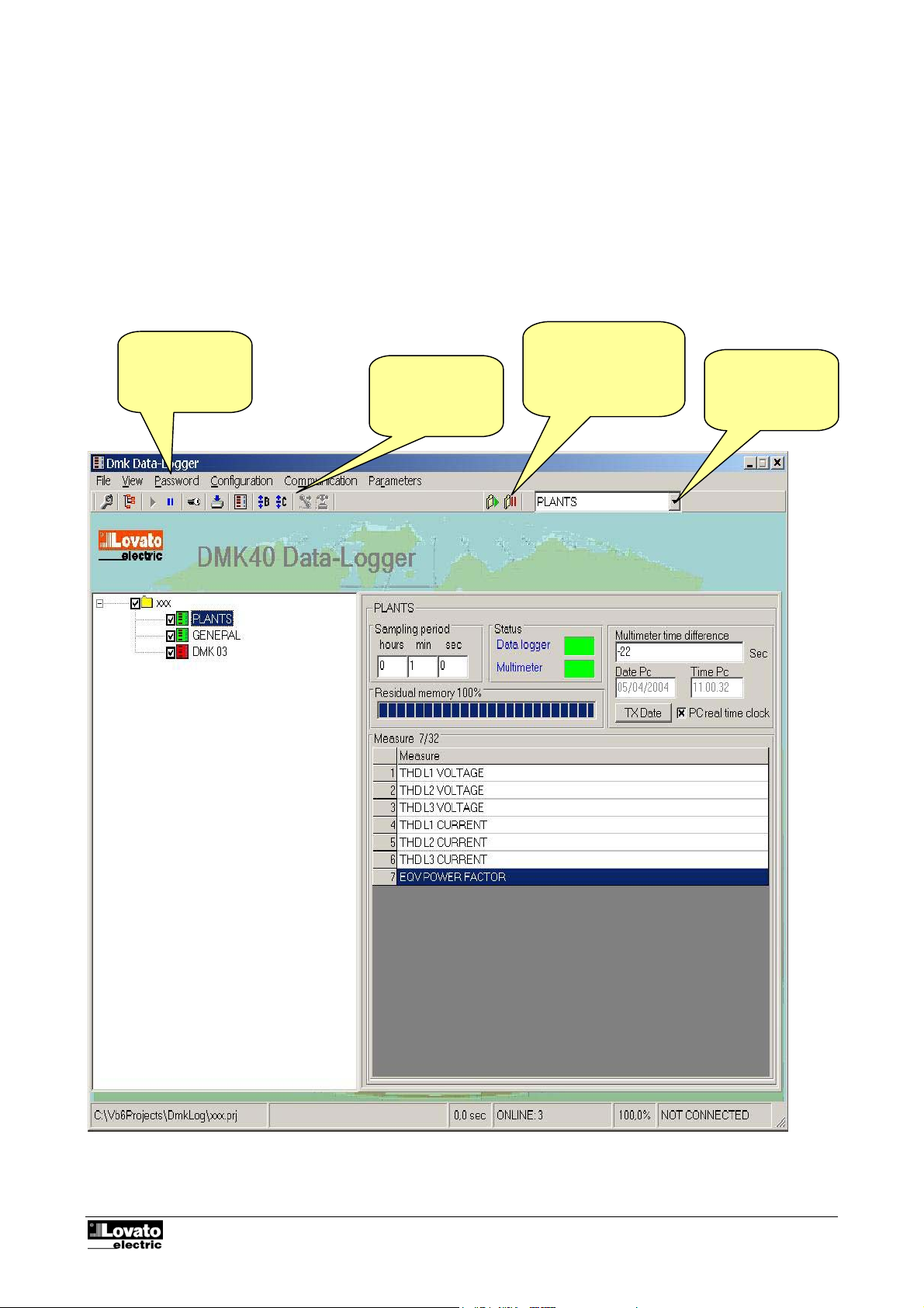
The main window of the program contains all the menus and the toolbars for access to the various functions.
As they may modify the configuration of the software, some of these functions are protected by a password
and are therefore disabled when the program is started. The main window is illustrated in the figure below
showing the most frequently used controls.
Fig 1.1 – Main window
Window type
menu for data
settings and
display
Toolbar for fast
access to settings
and displays
Start and stop of the
acquisition system of
the multimeter
selected
Selection of the
multimeter in
RS485 network
Code: MSGB202$0500.doc 18/06/2004 P. 5 / 20
Page 6
System configuration
To configure a data logging system, a project must be opened or a new project must be created.
To do this, open the ‘File” window and select New or Open. Create or open the file required. The file opened
is in Ms-Access format and contains all the information regarding the data logging system.
To access configuration, enter the password which, after installation of the program is, by default, LOVATO.
Click on the password menu, enter Lovato and then confirm with OK.
System configuration is a very important phase as regards definition of software functioning. In particular, if
several multimeters are connected, attention must be paid to programming the parameters of each DMK
connected to the network.
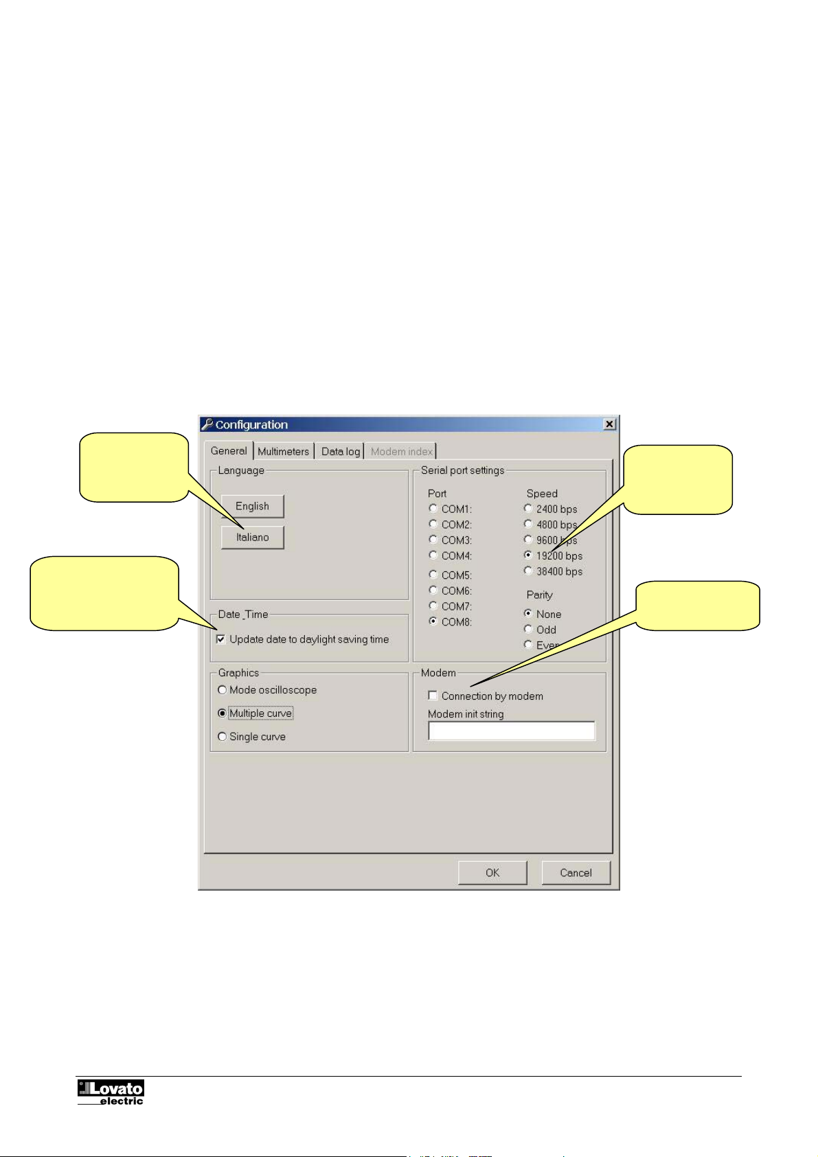
Before explaining the various functions of the program, the configuration window is illustrated below listing
the function of all the settings. A more detailed explanation of the purpose of each setting will be provided in
the following chapters.
Fig. 2.1 - Configuration-Options-General
Selection of the
language of the
program.
Correct multimeter date
and time based on
daylight saving or
standard time settino.
Settings of the
serial port of the
PC
Fix the multimeter
connection to be
modem.
Code: MSGB202$0500.doc 18/06/2004 P. 6 / 20
Page 7
A
A
r
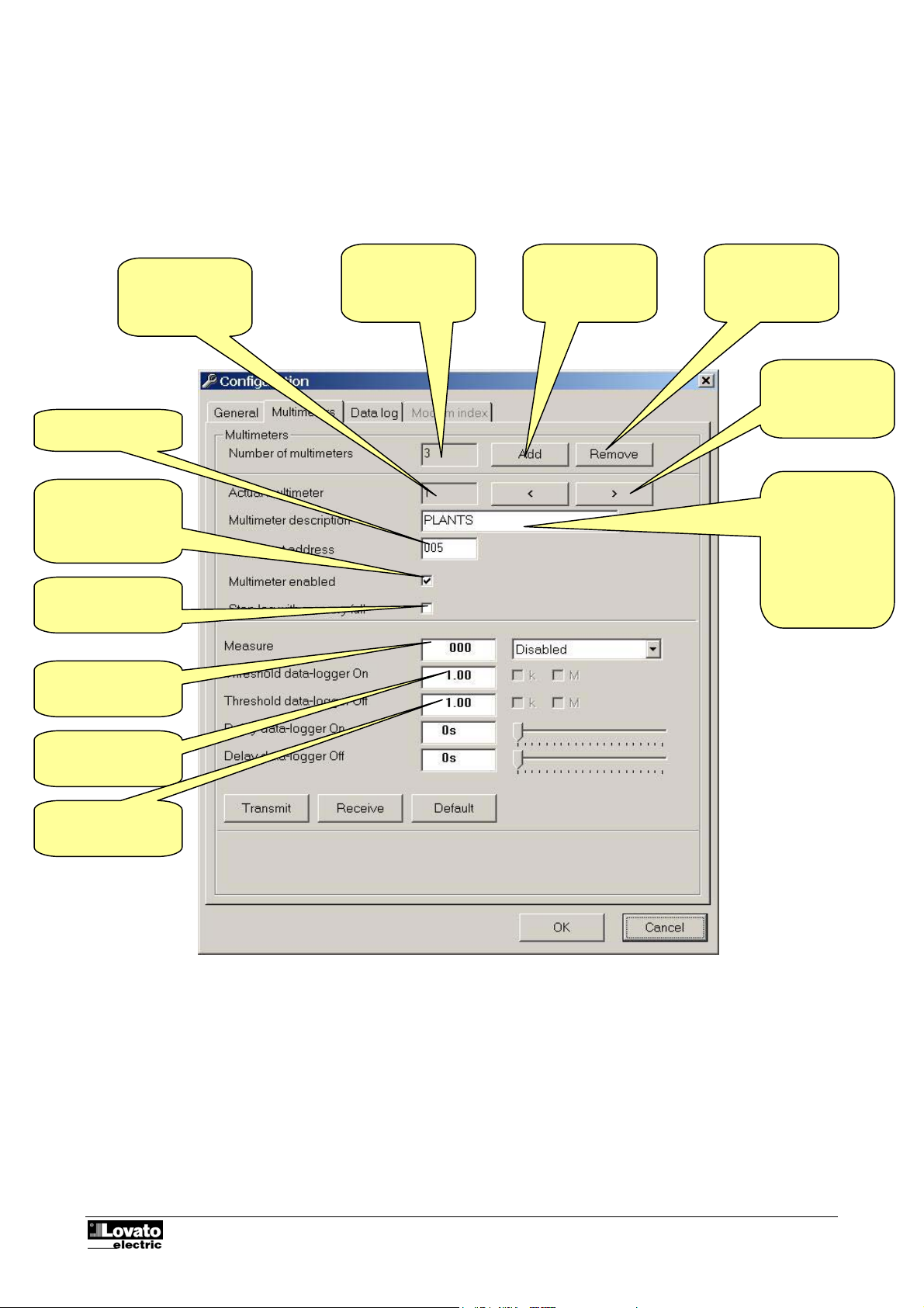
Fig. 2.2 - Configuration-Options-Multimeters
DMK currently
selected
ddress multimete
Total number of
DMKs configured
dds a new DMK
in the
configuration of
the network
Removes a DMK
from the
configuration of
the network
Selects the
previous/next
DMK
Enables/disables
serial
communication with
the DMK selected
Stop data-logger
when memory full.
Measure associated
to threshold.
Note 1
Note 1
Description of the
DMK. This
identifies the
multimeter and
will be displayed
in the selection
boxes, in the
alarms, in the data
collection etc.
Note 1: For example if threshold 1 is greater than threshold 2, the datalogger begins recording when threshold 1 is exceeded. When the value of the selected
measure is less than threshold 2, the datalogger is stopped. The two thresholds can be inverted. In that case, the datalogger will trigger when the value of
If the selected measure indicates all three phases, it is sufficient the measure value of one of the three phases is greater than threshold 1 to trigger the
the selected measure is less than threshold 1 but when it increases to greater than threshold 2, the datalogger will stop.
datalogger. The same procedure is done to stop the datalogger.
Code: MSGB202$0500.doc 18/06/2004 P. 7 / 20
Page 8
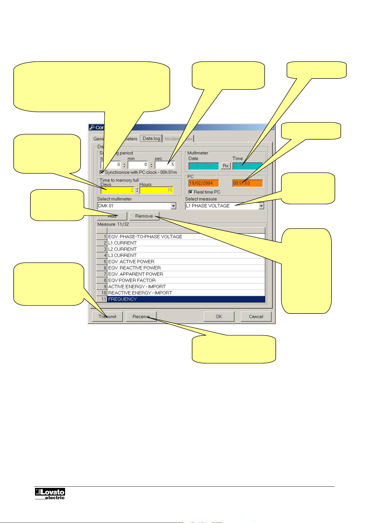
Fig. 2.3 - Configuration-Options-Data collection
If this checkbox is selected, the energy samples will be
carried out in synchronization with the real-time clock of the
PC.
For instance, if the sampling time is 1 hour, the sampling will
be done at 0:00, 1:00, 2:00 etc.
If this checkbox is not enabled, the sampling could be done at
0:33, 1:33, 2:33 etc.
Time used by the
memory to be filled
according to the set
measures and the
sampling time.
Selects the
multimeter from
which to sample
Transmits the settings
made.
Note: on transmitting the
settings, all the data
saved in the DMK40 will
be lost
Interval of time between
saving of one record and
the next
View the DMK real
time clock.
Setup Real time
clock of DMK
Selects the data
item to be
sampled
Eliminates the
item selected
from the list.
Note:
if a field is
eliminated from
the strucutre of
the Data
collection
database, the
currently saved
record is lost
Receives the settings saved in
the DMK40.
Code: MSGB202$0500.doc 18/06/2004 P. 8 / 20
Page 9
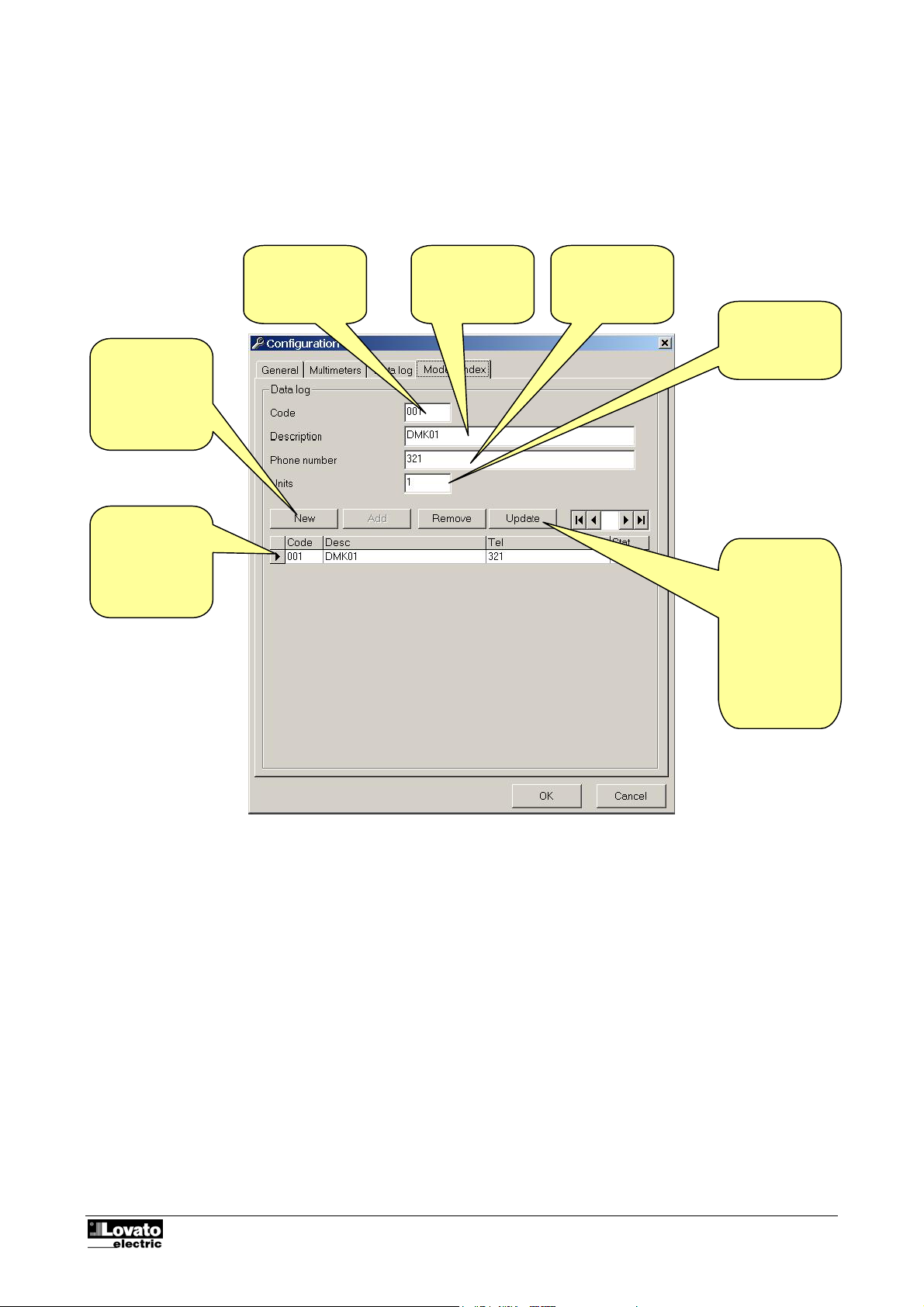
Figure 2.4 - Configuration-Options-Modem Index
If the software is configured for connecting via modem, it is possible to store a list of the various installations,
that is a list of places where a DMK network with modem is installed. For each installation, the user can
define a code, a name and the corresponding phone number of the modem on the field. This way, when
wanting to connect with a particular installation, it will be possible to dial it directly from this list. For each
installation it is possible to define if one or more units are installed and associate an initial page to be loaded
once connection has been established.
To enter a new
record, first click
on New, fill the
fields and then
click on Add.
To eliminate a
record, first
select it in the
table, then click
Remove button.
Installation
code. They must
all be different.
Description of
installation
Phone number
of modem to be
called
Number of DMK
units connected
to the modem.
To modify an
existing record,
first select it
from the table,
then do your
modification in
the field above,
finally click on
Update.
Important note:
Normally the user connects its DMK network to the PC without modem. This allows to configure each
multimeter, defining the name, the full-scale value for all the measurements etc (this are the configurations
that are entered in the Configuration-Options-Multimeters window, see figure 2.2).
When using modem connection, all this setting can be used only if the remote connection is done always to
the same DMK network, that is, if there is only one record in the Modem index because the user dials always
the same number. In this case, the couple of modems are used to reach a longer distance, but the
communication is the same as for direct connection.
The concept changes if there are more than one DMK networks in the field. In this case, each network may
be different from the other, having different number of DMKs, working with different voltage etc.
The user can select one installation, connect to it and see the DMK status, then disconnect and dial another
phone number to connect to another DMK network.
Code: MSGB202$0500.doc 18/06/2004 P. 9 / 20
Page 10
Display menu
Data collection
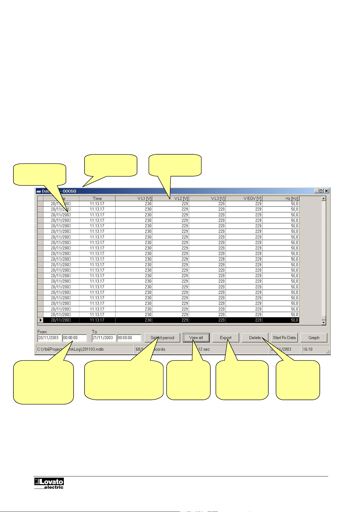
The variables defined in the Data collection configuration page (Fig. 2.3) are unloaded from the multimeter
by pressing the ‘Start Rx data’ key. The same data are saved in an Ms-Access format database.
The data collected can be displayed in table form with the Display-Data collection menu or clicking on the
matching icon on the toolbar.
Fig. 3.1 – Display-Data collection
Sampling date
and time
Number of
records selected
Values of the
variables sampled
Display period
selected. Extracts the
values within a
specific interval of
time from the
database.
Opens the window for
specification of the interval of
time to be selected
Code: MSGB202$0500.doc 18/06/2004 P. 10 / 20
Displays all
the record of
the database
Permits export of
the data selected
in ASCII or Excel
text files
Deletes the
data selected
from the
database
Page 11
play
Graphs
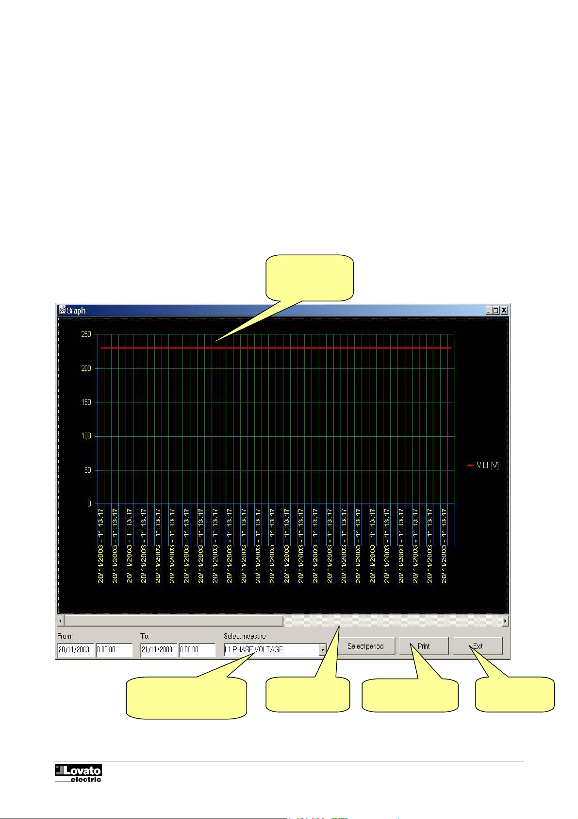
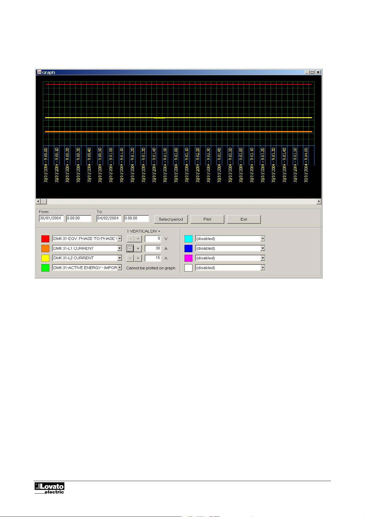
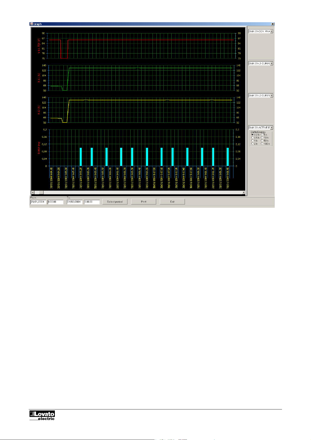
The data collected in the Data collection databases can be displayed in the form of graphs (trend). This
provides an immediate view of the trend of the most important measurements or the possibility of comparing
the values of two different parts of the system in the same graph. To open the window of the graph, select
the Display-Graph menu or click on the matching icon of the toolbar.
This type of graph is very similar to t hat of an oscilloscope. The time is indicated on the X (horizontal) axis.
The horizontal time scale is common to all the measurements displayed and is shown with indication of the
sampling date and time.
Using the specific Select period button, you can select the display start and end period.
Fig. 5.1 – Display-Graph
Bright color = data
sampled
Selects the measurement to
be associated to the red
trace
To scroll the
graph horizontally
Selects start/end of
display
Prints the
window
ed
dis
Code: MSGB202$0500.doc 18/06/2004 P. 11 / 20
Page 12
Code: MSGB202$0500.doc 18/06/2004 P. 12 / 20
Page 13
Code: MSGB202$0500.doc 18/06/2004 P. 13 / 20
Page 14
Front panel
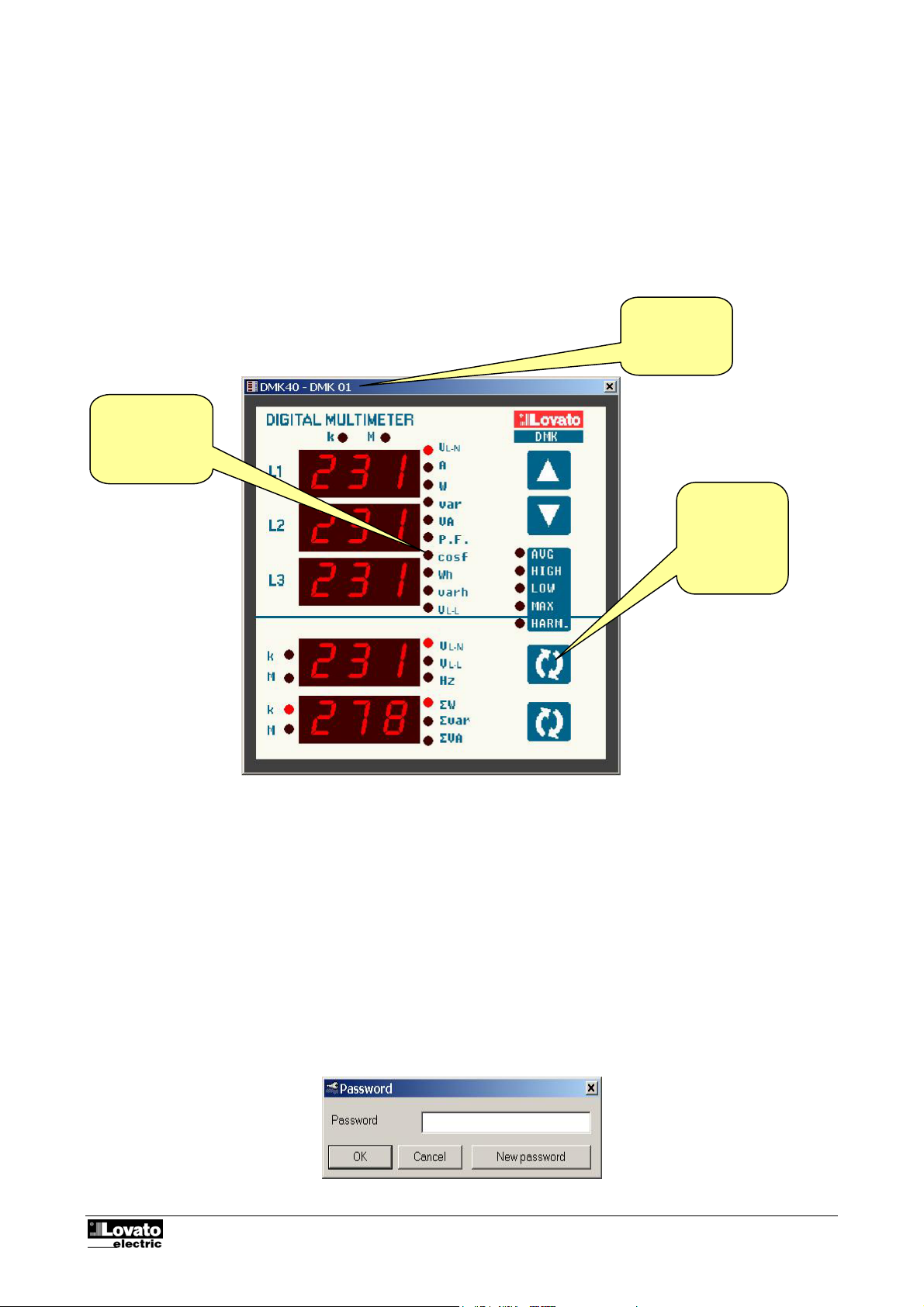
You can display a 'virtual' representation of the front panel of the DMK on the monitor of the PC using the
remote control software. When you access this window from the Display-Front Panel menu, the front panel of
the DMK is shown, with real-time display of the readouts and leds in their current status. Clicking with the
mouse on the keys, you can select the measurements and functions in the same way as on the physical
multimeter. However, you cannot access those functions (such as parameter programming, reset counters,
etc.) that require simultaneous pressing and/or holding down of the keys.
Note:
The quality of the graphic representation of the front panel may vary according to the graphic resolution of
your PC and/or the monitor settings used.
Fig. 7.1 – Display-Front panel
Real-time
display of the
status of the
readouts and
leds
Name of the
multimeter
selected
Clicking on the
keys has the
same effect as
on the real
panel
Password
When the program is started, some of the functions are disabled. You can enter the password that permits
access to all the functions, in particular those listed below, from the Password menu:
• Modification of the settings of the remote control
• Modification of the password
• Elimination of records from the Alarms and Data collection databases
• Access to the page editor
• Modification of the setup parameters of the DMK connected
Fig. 8.1 – Password
Code: MSGB202$0500.doc 18/06/2004 P. 14 / 20
Page 15
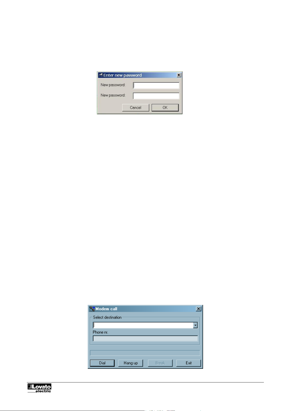
At the time of initial installation, the password is LOVATO. You can record a new, personalized password
subsequently, clicking on the New password button and then entering the new password you have chosen
twice consecutively.
Fig. 8.2 – New password
Communication menu
Online
The Communication-Online menu allows to re-establish the serial link after it has been stopped by the user
with the Offline command. When clicking Online, the software executes a complete scan of all configured
DMK, to verify their status.
Offline
With communication-Offline the user has the possibility to temporarily suspend the serial communication link
between the PC and the DMK network.
This command is to be used when, for instance, it is necessary to modify the network wiring or when DMK
are to be switched off. The System Offline status is displayed on the main page Toolbar (at the bottom of the
main window).
The system passes automatically in Offline mode when the user opens the Configuration window.
Modem Call
To connect to one or several DMK via a couple of modems, it is necessary to select the Modem connection
checkbox in the Configuration-Options-General window. Selecting modem communication will automatically
change the communication protocol used by the software, from the standard Modbus RTU to Modbus ASCII,
which can be used with modems. From the user point of view, the difference between those two protocols is
only a little slower speed in case of the ASCII protocol, due to its length that is double than the RTU and the
modem modulation that requires also a certain amount of time.
When the program is configured for modem communication (see Configuration-Options-General window) it
automatically shows the modem call dialog after it has been started, because it is not possible to
communicate with the DMK before dialing the phone number of the remote modem. The same window can
be opened manually using Communication-Modem call menu or the dedicated pushbutton on the toolbar.
Figure 8.3 - Communication-Modem call
Code: MSGB202$0500.doc 18/06/2004 P. 15 / 20
Page 16

Once the window illustrated has been opened, from the pull-down box choose the name of the installation
with which you want to be connected. The names entered in the Modem index during configuration will be
displayed. Once the choice has been made, the corresponding phone number appears in the box below.
Click the Dial button to start the connection procedure.
At this point the program will instruct the modem to make the call. While waiting, the sliding blue bar of the
maximum time allowed for making the connection will be seen (1 minute). The modem called will take the
line and exchange the usual handshaking messages with the answering modem. At the end of this
procedure, if everything has been carried out correctly, the PC status bar will show a message informing the
user that connection has taken place and the program will switch automatically to the Online mode. If any
errors occur, carefully check the connections and if necessary follow the Troubleshooting guide given in
appendix A of this manual. Normally connection is not critical since very common and absolutely standard
procedures are used. With the Break button it is possible to block the calling procedure, while Hang up ends
a communication already in progress.
Hang up
This command interrupts a modem connection, closing the telephone line. It is the equivalent of hanging up
the handset in an ordinary phone call. It is carried out automatically every time you exit the program.
Code: MSGB202$0500.doc 18/06/2004 P. 16 / 20
Page 17
Parameters menu
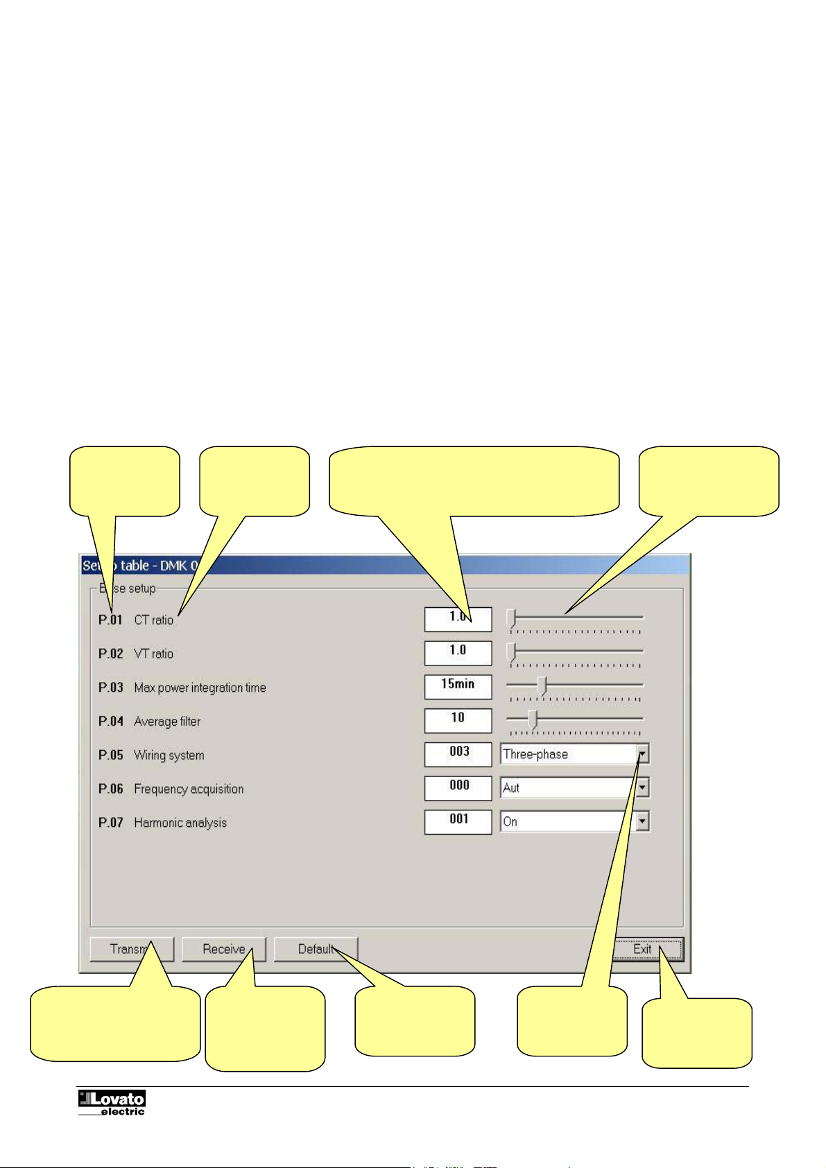
You can view and modify the setup parameters of the multimeters from the specific Parameters menu. This
method of accessing DMK settings is handier and more immediate compared with direct access from the
front keypad of the multimeters as, using the PC; the following are displayed:
• Code of the parameter
• Description in the language set
• Value set
• Graphic bar or drop-down box with possible options
The parameters have been grouped in four menus that reflect the organization described in the operations
manual and in the Addendum of the DMK. The following four menus are available:
• Basic setup (basic settings such as CT, VT ratio, etc.)
• Advanced setup (settings of the digital outputs)
• Capacitor overload setup (parameters relating to the capacitor protection function).
Basic setup
Fig. 9.1 – Parameters-Basic setup
Code of the
parameter
Description
Numeric value of the parameter. Highlighted in
yellow if different from the factory-set default
value. Double clicking on this box, you can set the
parameter with the numeric keypad
Graphic bar.
Drag this with the
mouse to modify the
setting
Transmits the values
displayed to the DMK and
saves them.
Enabled only with
Code: MSGB202$0500.doc 18/06/2004 P. 17 / 20
Receives the
values from the
DMK and displays
them in the
window
Resets the factory
default values
Drop-down box
with possible
options
Closes the
setup window
Page 18
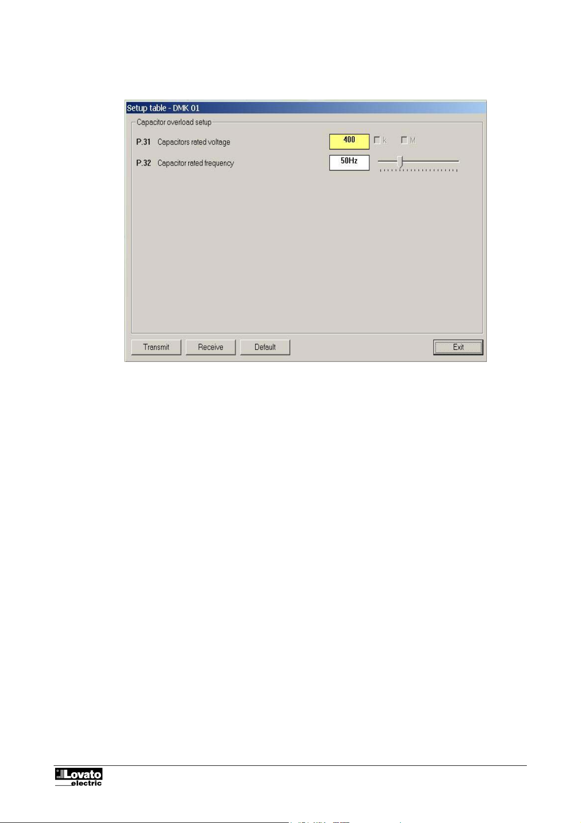
Capacitor overload setup
Fig. 9.3 – Parameters-Capacitor overload setup
Save-Load-Print
You can save the values of the setup parameters (of all four menus) on your hard disk in ASCII text file for
fast, easy reloading in another multimeter. This function is particularly useful when programming a set of
multimeters with the same settings or when you want to file the original settings of a system. To save the
parameters on disk, select the Parameters-Save to file menu and enter the name of the file. This type of file
has an .PAR extension. To reverse the operation, i.e. to transfer a file from PC to the DMK, use the
Parameters-Load from file menu.
Using the Parameters-Print menu, you can also print the settings and then file these together with the other
documentation of the system
Code: MSGB202$0500.doc 18/06/2004 P. 18 / 20
Page 19

APPENDIX A – Connection modes
Connection via standard modem
To make a remote connection via a switched telephone line the use of a pair of modems is necessary.
Lovato Electric guarantees correct operation of the connection using modems of the following type:
• 3-Com U.S. Robotics 56K model 5630
Though correct operation is possible also with modems of other types, in this manual all the configuration
commands (variables depending on the manufacturer) and the connection diagrams will refer to the abovementioned modem model.
Though very simple in conception, connection via modem requires that the installer have a minimum
of experience concerning the problems connected with serial communication, modem programming,
types of telephone lines, etc. In an attempt to simplify the configuration procedure as far as possible,
we have subdivided the operations to be carried out in the following steps:
1. Modem configuration at the DMK end
From the DMK end the modem must be configured before it can be used. Configuration serves to
implement the following functions:
• Disable the echo
• Set a communication speed (this must be the default speed for DMK also)
• Permanently store the two previous settings as default at switch on
To make these configurations, the modem to be connected to the RS232/RS485 converter will have to
be momentarily connected to the PC with its standard cable. Then start the PM.EXE program (supplied
together with this software) and press the Program modem button. Wait for the confirmation message
and then disconnect the modem from the PC and connect it to the DMK. The PM.EXE program transmits
the following configuration string to the modem:
AT E0 &N6 &U6 &W0 <CR> (commands valid for modem model 5630)
To select higher baud rates in the modem, digit Nx & Ux, whereas x is the rate code to be obtained.
Take into account the rate to select is the one at the multimeter end.
If the program PM is used, the AT&Nx and AT&Ux string must be changed in the modem.txt file found in
the same directory where the PM program is installed.
If the user is familiar with terminal emulation programs (such as Windows Hyperterminal) this
programming can be done manually without the aid of the PM.EXE program. In this case, it will be
necessary to set the serial interface at 9600 Baud, 8 bit, No parity, 1 stop bit and type in the above string
from the keyboard. On pressing return the modem will answer with OK confirming that programming has
taken place.
2. DMK configuration
Also the DMK needs a configuration to be able to converse with the modem.
• From the front panel of each DMK, enter the serial communication setup menu (see the DMK Addendum
Manual)
• Check the serial address (parameter P.41). If several DMKs are connected to a RS-485 bus, set each of
them with a progressive serial address starting from 001.
• On each unit, select the Modbus ASCII protocol (parameter P.44 set to ASC).
• If you want the DMK to answer when modem rings (modem without auto-answer) then set parameter
P.45 to 001, only for the DMK with serial address 01.
• Otherwise, if you want the modem to answer automatically itself, then enable the modem auto-answer,
setting its parameter S0 to 001 (with command ATS0=1 &W0) and leave the first DMK with P45 to 000.
Code: MSGB202$0500.doc 18/06/2004 P. 19 / 20
Page 20

3. System connection
• Connect the DMK-side modem to the RS232/RS485 interface converter using 51C9 cable.
• Connect the RS232/RS485 interface converter to the DMK network using a shielded twisted pair cable
(see wiring diagram in the following page).
• Connect the second modem to the PC with the standard cable provided with the modem. The PC-side
modem does not require any particular programming (it must be left at factory defaults).
• Connect both modems to the respective telephone lines. For the first tests you are advised to use two
internal lines in the same office to keep the call under control.
4. Configuration of the DMKLOG program
• Start the DMKLOG program from the PC with the modem already connected and powered.
• Choose the Configuration-Options menu
• Set the Connection via modem box from the General table.
• If the Modem Index table is empty, enter a record with the name of the installation and the phone
number corresponding with the telephone line of the modem connected to the DMK.
• Click on OK to close and save the Options window.
5. Online Connection
• Choose Call with modem from the Communication menu
• From the pull-down box choose the name of the installation to be called. The corresponding telephone
number (previously loaded in the Modem index) will be shown in the box below.
• Click on Dial
• At this point, the modem at the PC end calls the DMK modem. After a few rings the DMK modem and
the program switch automatically to the online mode.
• To end the connection, choose Modem-Hang up from the Communication menu
In the event of problems…
If during the attempted call the modem connected to the DMK does not ‘ring’, this means that the call fails to
reach its destination. In this case, carry out the following checks:
• Try dialing the telephone number of the line to which the DMK is connected using a normal telephone.
The modem called should give off sounds that ought to be heard in the handset. If this does not happen,
there are problems on the telephone line or on the switchboard.
• Check that PC modem is powered and connected with the cable to the correct serial port (the one set in
Communication-Serial port)
If the modem called rings repeatedly but the connection fails to be established
• Check the DMK programming (in particular about auto-answer, see previous point 2)
• Check modem programming (in particular about auto-answer, see previous point 2)
• Check the integrity and the polarity of DMK-Converter RS-485 twisted-pair cable
• Check the integrity of modem-converter cable 51C9
• Check if when the phone rings, the yellow LED on the interface converter blinks briefly. This means that
the modem is sending the RING message to the converter and this is sending the message to the
DMKs.
PENTIUM is a registered trademark of Intel Corporation
WINDOWS is a registered trademark of Microsoft Corporation
Code: MSGB202$0500.doc 18/06/2004 P. 20 / 20
 Loading...