

Page 1
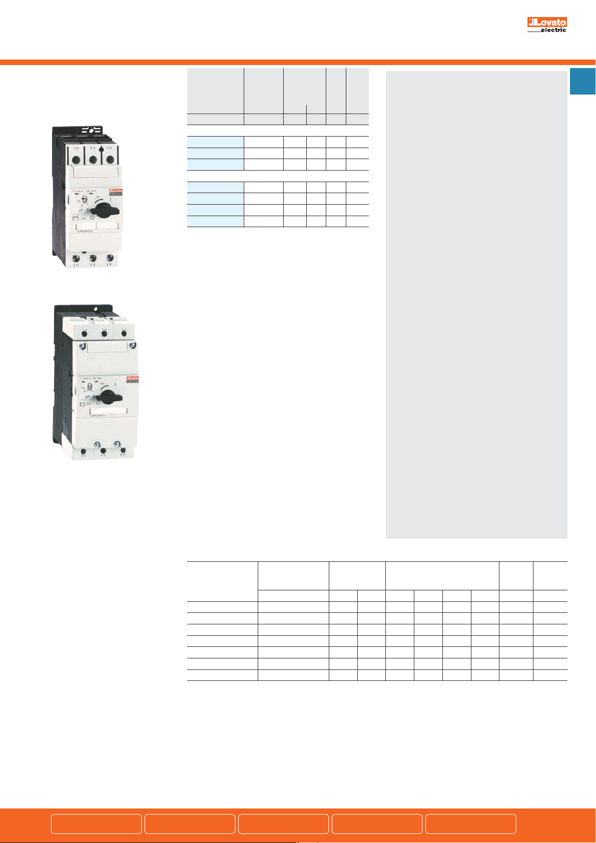
Motor protection circuit breakers
With thermal and magnetic trip releases
Motor protection circuit
breakers SM2A - SM3A
up to 100A
11 SM2A...
Order Thermal Short circuit Qty Wt
code trip breaking per
adjustment
range at 400V
[A] [kA] [kA] n° [kg]
IEC breaking capacity Icu 50kA at 400V.
11 SM2A 68 28-40 50 25 1 1.040
11 SM2A 72 36-45 50 25 1 1.040
11 SM2A 76 40-50 50 25 1 1.040
IEC breaking capacity Icu 50kA at 400V.
11 SM3A 84 45-63 50 25 1 2.266
11 SM3A 88 57-75 50 25 1 2.266
11 SM3A 92 70-90 50 25 1 2.266
11 SM3A 96 80-100 50 25 1 2.266
capacity (IEC)
Icu Ics
pkg
General characteristics
The SM2A and SM3A types are circuit breakers with a
wide adjustment range, 28 to 100A, in only two frame
sizes enabling motor control and protection up to 45kW
at 400V/75HP 480V/100HP 600V.
A magnetic trip indicator and padlockable operating
handle are integrated on the SM2A and SM3A breakers.
Both are suitable for isolation according to IEC/EN 60947
standards.
Their high breaking capacity consents to exclude
protection fuses on the majority of the installations.
Operational characteristics
– IEC rated insulation voltage Ui: 690V
– IEC rated impulse withstand voltage: 6kV
– IEC rated frequency: 50/60Hz
Maximum rated current: 50A (SM2A) and 100A (SM3A)
–
– Number of adjustment ranges:
SM2A: 3 (28 to 50A)
SM3A: 4 (45 to 100A)
– IEC breaking capacity: See table on page 1-17
– Power dissipation:
SM2A: 7.1-20W
SM3A: 10-38W
– Magnetic tripping: 13In max
– IEC thermal tripping class: 10
– Phase failure / Single phase sensitive
– Life (cycles): Mechanical Electrical (Ie AC3)
SM2A 50,000 25,000
SM3A 50,000 25,000
– Mounting:
SM2A - Screw fixing or on 35mm DIN rail
(IEC/EN 60715)
SM3A - Screw fixing or on DIN rail 35mm
(IEC/EN 60715) or 75mm (IEC/EN 60715)
– Mounting position: Any
– IEC utilisation category: A
– IEC degree of protection: IP00.
1
11 SM3A...
Certifications and compliance
Certifications obtained: EAC; UL Listed, for USA and
Canada (cULus - File E155982); CSA certified (File 73212).
See UL/CSA details under NOTE below bottom table.
Compliant with standards: IEC/EN 60947-1,
IEC/EN 60947-2, IEC/EN 60947-4-1, UL508,
CSA C22.2 n° 14.
NOTE: When more than one breaker are mounted, side by side, without
leaving space between each to consent free air circulation on the
breaker sides, and have simultaneous operation, the thermal trip
adjuster must be positioned at a value 15% greater than the rated
motor current.
Maximum UL/CSA horsepower rating
Type
SM2A 68 28-40A 3 7
SM2A 72 36-45A 5 7
SM2A 76 40-50A 5 10 15 20 40 50 50 200
SM3A 84 45-63A 5 15 20 25 50 60 63 250
SM3A 88 57-75A 7
SM3A 92 70-90A 10 20 30 30 75 100 90 350
SM3A 96 80-100A 10 20 40 40 75 100 100 400
NOTE:
For SM2A types: UL Listed for USA and Canada and CSA certified as manual motor controller, short circuit 65kA 480V; 25kA 600V; max fuse / CB (see table).
Suitable for group installation.
CSA: Maximum fuse / CB 350A. UL: SPCD according NEC; suitable as motor disconnect 600Y/347V.
Suitable as tap conductor protection in group installation 65kA 480Y/277V, 25kA 600Y/347V. Maximum fuse / CB 500A. Trip amps 125%.
For SM3A84 and SM3A88 types: UL Listed for USA and Canada and CSA certified as manual motor controller, short circuit 65kA 480V; 30kA 600V; max fuse /
CB (see table). Suitable for group installation.
CSA: Maximum fuse / CB 500A. UL: SPCD according NEC; suitable as motor disconnect 600Y/347V.
Suitable as tap conductor protection in group installation 65kA 480Y/277V, 30kA 600Y/347V. Maximum fuse / CB 1200A. Trip amps 125% .
For SM3A92 and SM3A96 types: UL Listed for USA and Canada and CSA certified as manual motor controller, short circuit 65kA 480V; 10kA 600V; max fuse /
CB (see table). Suitable for group installation.
CSA: Maximum fuse / CB 500A. UL: SPCD according NEC; suitable as motor disconnect 480Y/277V.
Suitable as tap conductor protection in group installation 65kA 480Y/277V. Maximum fuse / CB 1200A. Trip amps 125%.
The appropriate thermal trip range of the controller should be selected on the basis of the motor nameplate full-load current since the horsepower ratings
given are for indication and reference purposes only.
Single-phase horsepower ratings are based on wiring the three poles in series; see wiring scheme on page 1-15.
Thermal 1 Phase [HP] FLA Max
adjustment range (not mentioned
[A] 120V 230V
by UL/CSA) 600V CB
200-208V
1
/2 15 15 30 40 40 150
1
/2 15 15 30 40 45 175
1
/2 15 25 25 60 75 75 300
3 Phase [HP]
230V 480V 600V [A] [A]
max at Fuse /
Add-on blocks/Accessories
pages 1-8 and 9
Dimensions
page 1-14
Wiring diagrams
pages 1-15 and 16
Technical characteristics
pages 1-16 and 17
1-3
 Loading...