

Page 1
Rotary cam switches
Technical characteristics
SELECTION GUIDE
The choice of a rotary cam switch and the relative type are based on the functional diagram
and the type of application as well.
IEC standards provide a comprehensible and quick classification of the most frequent
utilisation categories:
AC1: Connection and disconnection of non-inductive or slightly inductive loads
(cosϕ≥0.95)
AC21: Resistance furnaces
AC3: Starting and switching off motors during running
AC23A: Switching of motor loads or other highly inductive loads
AC15: Control of electromagnetic loads
For DC applications. the rotary cam switches are used for the switching of minor loads or
in control circuits. such as:
DC13: Control of electromagnets
DC21A: Switching of resistive loads
DC23: Switching of highly inductive loads
Other prescriptions and recommendations concerning the use of cam switches as auxiliary
equipment of electrical machines are given in IEC/EN 60204-1 standards and specifically as
given under utilisation.
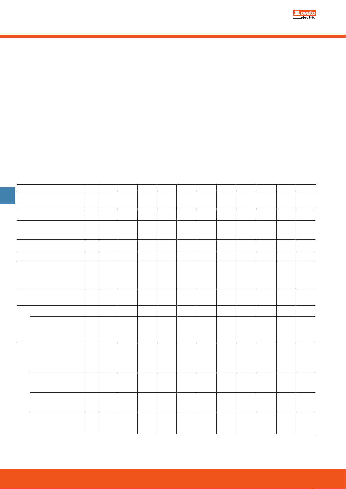
GX16 GX20 GX32 GX40 GN12 GN20 GN25 GN32 GN40 GN63 GN125TYPE
Rated insulation voltage
10
Ui IEC/EN
UL/CSA
Rated impulse withstand voltage
Uimp IEC/EN 60947-3
Conventional free air thermal
current Ith IEC/EN
Rated operating
voltage (switch disconnect) ∂
Operatioanl impulse
voltage (switch disconnect)
Maximum fuse size for
short-circuit protection
In (gG)
Short-time
withstand current
Icw 1sec
Rated operational current
Ie AC1/AC21A (IEC/EN)
380-400V
660-690V
Motor power for switches
in AC utilisation categories
AC3 (IEC/EN) 220-230V
500-690V
220-230V
380-440V
AC23A (IEC/EN) 220-230V
500-690V
220-230V
380-440V
∂ Valid for systems with earthed neutral, overvoltage category III, pollution degree 3.
UL/CSA
50kA
110V
AC15 (IEC/EN) 220-230V
3 phases 380-440V
1 phase (2 poles) 110V
3 phases 380-440V
1 phase (2 poles) 110V
∂
∂
(general purpose use)
10kA
25kA
63kA
690 690 690 690 690 690 690 690 690 690 690
V
600 600 600 600 600 600 600 600 600 600 600
V
6 6 6 6 6 6 6 6 6 6 8
kV
16 20 32 40 16 20 25 32 40 63 125
A
12 15 32 40 15 20 30 40 50 60 130
A
440 440 440 440 480 480 480 480 480 480 690
V
4 4 4 4 4 4 4 4 4 4 6
kV
20 20 40 40 16 20 25 32 40 63 125
A
16 16 35 35 10 16 25 32 40 63 100
A
– – 32 35 – – – 32 40 63 100
A
– – – 35 – – – – 40 63 100
A
250 250 800 800 200 250 400 800 1000 1600 2100
A
16 20 32 40 12 20 25 32 40 63 125
A
10 10 25 25 10 10 16 25 25 32 40
A
8 8 20 22 8 8 12 20 22 25 28
A
4 6 10 12 4 6 8 10 12 15 15
A
3 3.7 5.5 7.5 1.5 1.5 2 2 2 4 5
A
3.5 3.7 7.5 7.5 2.5 3 5.5 7.5 8 11 18.5
kW
4.5 5.5 11 15 4 5.5 7.5 11 15 18.5 37
kW
5.5 5.5 11 15 5.5 5.5 7.5 11 15 18.5 33
kW
0.55 0.75 1.8 2.2 0.8 0.8 1.5 2.2 3 3.7 5
kW
1.5 1.8 3.5 4.4 1.5 2.2 3 4 6.5 6.5 11
kW
2.2 3 5.5 7 2.2 3 5.5 6.5 8 11.5 15
kW
3.7 4 8 9 3 5 6.5 8 8 12.5 30
kW
6.5 7.5 15 18.5 5.5 7.5 11 15 18.5 30 45
kW
7.5 7.5 15 15 7.5 7.5 11 18.5 22 30 37
kW
0.75 0.75 2.2 3 0.8 0.8 1.5 2.2 3 3.7 5
kW
1.8 2.2 3.5 5.2 1.7 2.5 3.7 4 6 7.5 11
kW
3 3.5 6 7.5 3 3.7 5.5 7.5 11 12.5 15
kW
UTILISATION
MAIN SUPPLY DISCONNECTING SWITCH WITH
EMERGENCY-STOP OPERATION:
Red operating handle with yellow background
–
– Lockable in open position (OFF).
EMERGENCY-STOP SWITCH
– Red operating handle with yellow background
– Independent operation and the breaking of the load circuit of switching devices before
the opening of its main contacts
– Rated capacity is to sufficient in order to break the sum of the rated operating currents
of all the connected equipment
– Breaking capacity equal to the current of the largest motor when stalled (locked rotor)
together with the total of the normal running currents of the other motors or loads.
MAIN SUPPLY DISCONNECTING SWITCH
– Used to disconnect all live electrical equipment from the power supply circuit
– Contact clearance distance is to comply with
IEC/EN 60947-3 standards
– Provided with a means in order to be locked in the OFF position
– Selection of current breaking according to IEC AC1 and AC21 utilisation categories.
10-24
Page 2
Rotary cam switches
Technical characteristics
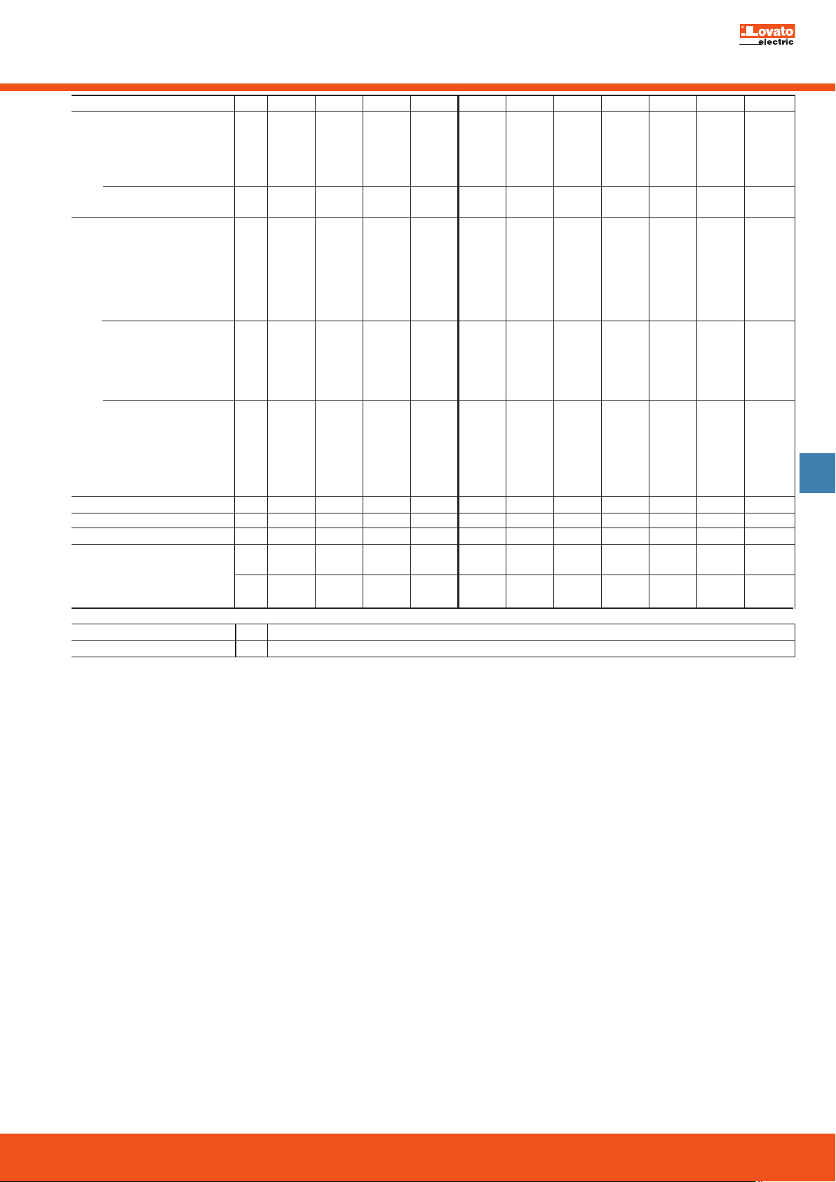
Motor power for
direct-on-line control
(UL/CSA-DOL)
3 phases
600V
1 phase (2 poles) 120V
230V
Motor power for switches in DC
utilisation categories
1 contact
DC21A
60V
Ie 110V
220V
440V
DC23A 24V
48V
Ie 60V
No. of contacts connected in
series are indicated in brackets
24V
DC13 48V
60V
Ie 110V
220V
440V
Mechanical life
Terminal screw
Tightening torque max
Conductor cross section
r: rigid/solid min. r/f
f: flexible/stranded
AMBIENT CONDITIONS
Operating temperature
Storage temperature
120V
230V
480V
48V
110V
220V
max. r/f
cycles
2 mm
2 AWG
2 mm
2 AWG
GX16 GX20 GX32 GX40 GN12 GN20 GN25 GN32 GN40 GN63 GN125TYPE
1.5 1.5 3 5 1.5 1.5 3 5 5 7.5 15
HP
3 3 7.5 10 3 3 5 10 10 15 25
HP
5 5 15 15 – – 10 15 20 25 50
HP
5 5 15 15 – – 15 15 20 25 40
HP
0.75 0.75 1.5 2 0.75 0.75 1.5 2 2 5 7.5
HP
1 1.5 3 5 1 2 3 5 5 10 15
HP
A
16 20 32 40 12 20 25 32 40 63 125
A
16 20 32 40 12 20 25 32 40 50 80
A
4 4 5 6 4 4 4 6 6 8 10
A
0.5 0.6 0.8 0.8 0.6 0.6 0.7 0.9 0.9 1 1.2
A
0.25 0.25 0.25 0.25 0.25 0.25 - - - - -
A
16(1) 20(1) 32(1) 40(1) 10(1) 20(1) 25(1) 32(1) 40(1) 50(1) 125(1)
A
16(2) 20(2) 32(2) 40(1) 10(2) 20(2) 25(2) 32(2) 40(2) 50(2) 125(2)
A
16(3) 20(3) 32(3) 40(3) 10(3) 20(3) 25(3) 32(3) 40(3) 50(3) 125(3)
A
10(3) 10(3) 15(3) 20(3) 5(3) 10(3) 12(3) 15(3) 20(3) 25(3) 50(3)
A
7(4) 8(4) 12(4) 12(4) 5(4) 8(4) 10(4) 12(4) 12(4) 15(4) 20(4)
A
16 20 32 40 12 20 25 32 40 63 125
A
14 16 25 32 10 16 20 25 32 40 100
A
12 12 16 16 8 12 16 16 16 28 50
A
0.8 1 3 3 1 1 1.5 3 3 3.3 4
A
0.3 0.4 0.5 0.5 0.4 0.4 0.4 0.5 - - -
A
0.15 0.15 0.15 0.15 0.15 0.15 - - - - -
6
5x10
M
3 3 4 4 3 3 3.5 4 4 5 2x5
Nm
0.5 0.8 1.2 1.2 0.5 0.5 0.8 1.2 1.2 2 2
2
2.5/2.5 2.5/2.5 10/6 10/6 2.5/2.5 2.5/2.5 4/4 6/4 10/6 16/10 50/50
5x10
6
5x10
6
5x10
6
3x10
6
5x10
6
5x10
6
5x10
6
5x10
6
5x10
14/14 14/14 8/10 8/10 14/16 12/14 10/12 8/10 8/10 6/8 1/0 / 1/0
2
0.5/0.5 0.5/0.5 1.5/1.5 1.5/1.5 0.5/0.5 0.5/0.5 0.5/0.5 1.5/1.5 1.5/1.5 2.5/2.5 2.5/2.5
20/20 20/20 16/16 16/16 20/20 20/20 20/20 16/16 16/16 14/14 14/14
°C
-25...+55
°C
-40...+70
6
1x10
10
6
10-25
 Loading...