

Page 1
Micro PLC
100% electricity
Page 2
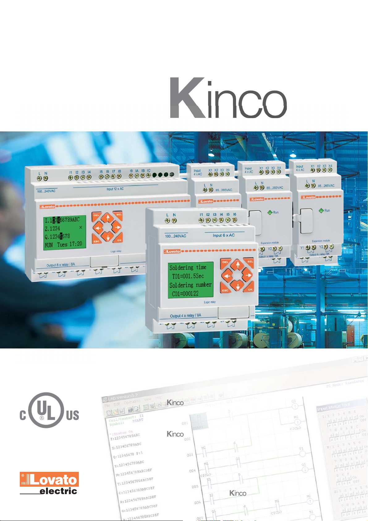
Micro PLC
is a micro PLC, compact in size yet with excellent
performance, suitable for the control and supervision of
low and medium complexity automatisms.
can efficiently be used in diverse fields of
industrial, service, private and residential applications,
because of the variety of its functions.
Packaging machines, industrial dishwashers, lighting
installations, irrigation systems, garbage disposal
machinery, barrier, door and gate controls are just a
few examples of where can be used.
Page 3
Expandable
Versatile
Smart
Simple
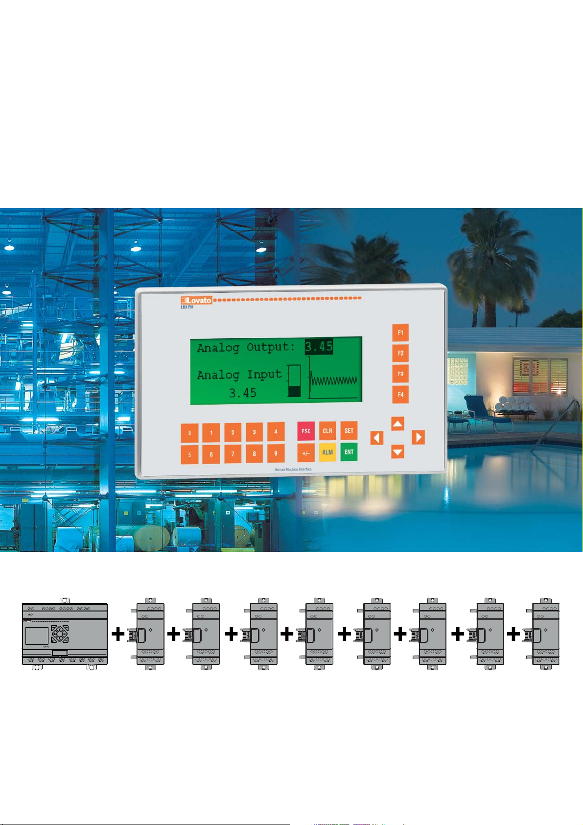
Maximum combinations
-
+
Q2Q1 Q4Q3
Base module
12 inputs
8 outputs
I6I5 A1 A2I1 I3I2 I4 I1 I3I2 I4
Q5 Q6 Q7 Q8
+
X3
X1 X2Y4X4
Input
4x AC
L N
AC 100~2 40V
Run
Output 4 x Re lay / 8A
Y2Y3Y1
4 inputs
+
4 outputs
X3
X1 X2Y4X4
Input
4x AC
L N
AC 100~240V
Run
Output 4 x Re lay / 8A
Y2Y3Y1
4 inputs
+
4 outputs
X3
X1 X2Y4X4
Input
4x AC
L N
AC 100~2 40V
Run
Output 4 x Re lay / 8A
Y2Y3Y1
4 inputs
+
4 outputs
• 24 digital inputs
(4 configurable as analog 0...10V inputs
• 20 digital outputs (relay, transistor or mixed)
• 4 analog inputs for PT100 temperature sensors
N.B. The sequence of the products given above must be respected for correct operation.
X3
X1 X2Y4X4
Input
4x AC
L N
AC 100~2 40V
Run
Output 4 x Re lay / 8A
Y2Y3Y1
4 inputs for
temperature
sensors PT100
X3
X1 X2Y4X4
Input
4x AC
L N
AC 100~2 40V
Run
Output 4 x Re lay / 8A
Y2Y3Y1
2 outputs
for 0...10V or
0...20mA signal
X3
X1 X2Y4X4
Input
4x AC
L N
AC 100~2 40V
Run
Output 4 x Re lay / 8A
Y2Y3Y1
2 outputs
for 0...10V or
0...20mA signal
X3
X1 X2Y4X4
Input
4x AC
L N
AC 100~2 40V
Run
Output 4 x Re lay / 8A
Y2Y3Y1
4 inputs
for
0...10V or
0...20mA signal
Modbus®-RTU
• 4 analog outputs configurable as 0...10V or 0/4...20mA
• 4 analog inputs configurable as 0...10V or 0/4...20mA
• 1 RS485 communication module.
X3
X1 X2Y4X4
Input
4x AC
L N
AC 100~2 40V
Run
Output 4 x Re lay / 8A
Y2Y3Y1
RS485
interface
Page 4

Small PLC
Exceptional performance
combines the facility of
numerous traditional devices, such
as control relays, timers, counters,
hour meters and so on.
The advantages are many:
Applications
Residential and
home automation
Timing and programming control
for:
• Lighting
• Garden and park irrigation and
pool filling systems
• Heating and air-conditioning
systems
• Roller shutters, blinds and
shades.
Industrial buildings
Timing and programming control
for:
• Automatic door, window and
gate opening and closing
cost reduction of materials and
installation time, space reduction,
easy reprogramming when needed,
and function adjustment of the
system for relay adaptation to new
Industrial machinery
• Machinery cycle control
• Speed control
• Operation feedback control
(temperature, speed, pressure,
etc.)
• Operating rate count
• Alarm verification and display.
installation requirements.
is available for 24VDC or
24VAC or 100-240VAC power
supply and with 10 to 44 inputs
and outputs.
Cold storage and
refrigeration
• Timers
• Temperature control
• Humidity-ventilation control
• Compressor controls.
Conveying and
transfer systems
• Conveyor belts
• Stop and go controls
• Automatic programmed
stopping
• Baggage handling controls
• Storage and car silos.
Level and pressure
control
• Automatic valve opening and
closing control
• Level controls
• Pressure controls
• Pump change
• Storage silo and tank filling and
draining.
Greenhouses
• Lighting
• Temperature control
• Humidity control
• Irrigation
• Sprinkling systems.
Lifting mechanisms
• Bridge crane control
• Roadway barriers and gates
• Automatic car garages
• Platforms
• Hoists and lifts.
Page 5
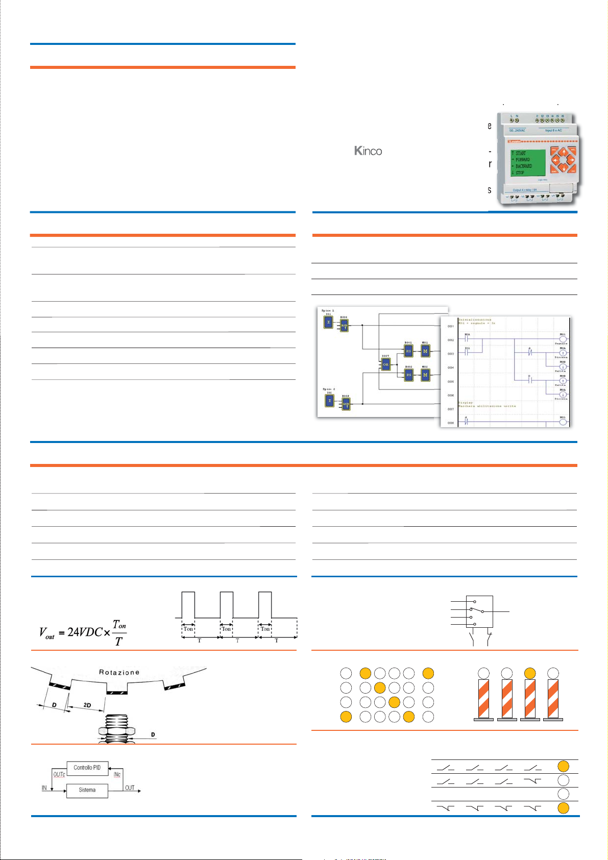
Features
Quick control board installation
Repetitiveness
Fl exibility
Language
PWM OUTPUT
SHIFT FUNCTION -
MULTIPLEXER
BOOLEAN LOGIC BLOCKS
PID FUNCTION
HIGH SPEED INPUT
- Fewer number of components
- Less wiring. Fewer number of connections.
- Less errors during panel building
- Considerable time saving.
- Quick correction of abnormal conditions at final testing
- Fast changes on control boards.
With a personal computer, two programming language logics can
be used: FBD (Function Block Diagrams) and LADDER (contact
scheme).
Both of these can be accomplished:
- Simulate the program directly “off-line” on a personal computer
to test if it runs correctly.
- Use the supervision mode to check the
project “on-line”.
On front, has 8 function keys, dedi-
cated to “on-board” programminng and for
status and variable supervision.
The 4 directional key can be configured as
function keys, programmable by the user.
Function blocks and memory
Timer (T) 31
(delay on/off, recycle, pulsing, ...)
Real Time Clock (RTC) 31
(daily, weekly, monthly and yearly mode)
Counter (C) 31
Analog comparator (G) 31
User’s pages (H) - 16 characters and 4 lines 31
Auxiliary relay - Scratchpad (M + N memory types) 63 + 63
Data register (DR) 240
Saving can be in memory storage of:
- Auxiliary relay
- Counter value
- Data register.
Functions
• Addition-Subtraction on variables
• Multiplication-Division on variables
• Comparators on variables
• HMI display for parameter viewing and programming
• PWM output
• High speed input (1kHz)
Program size
LADDER (contact scheme) 300 lines
FBD (function blocks) 260 blocks
• PID function
• Multiplexer
• Analog Ramp
• Register transfer (numerical variables and status)
• Shift function
• Boolean logic blocks
Pulse train generation with programmable
pulse time and frequency
IN: Heating switch on and required tempera-
OUT: Current room temperature
INc: Measured room temperature in a precise
OUTc: Temperature adjusting and controlling.
ture setting
point
Position and speed
detection
Selection of 1 of 4 values based
on the combination of two digital signals
Out 1
2
3
4
activation of pulsed outputs in sequence
Output activation based on a
series of digital singals
A
B
C
D
B
In 1 In 2 In 3 In 4 Out
... ... ... ...
Page 6
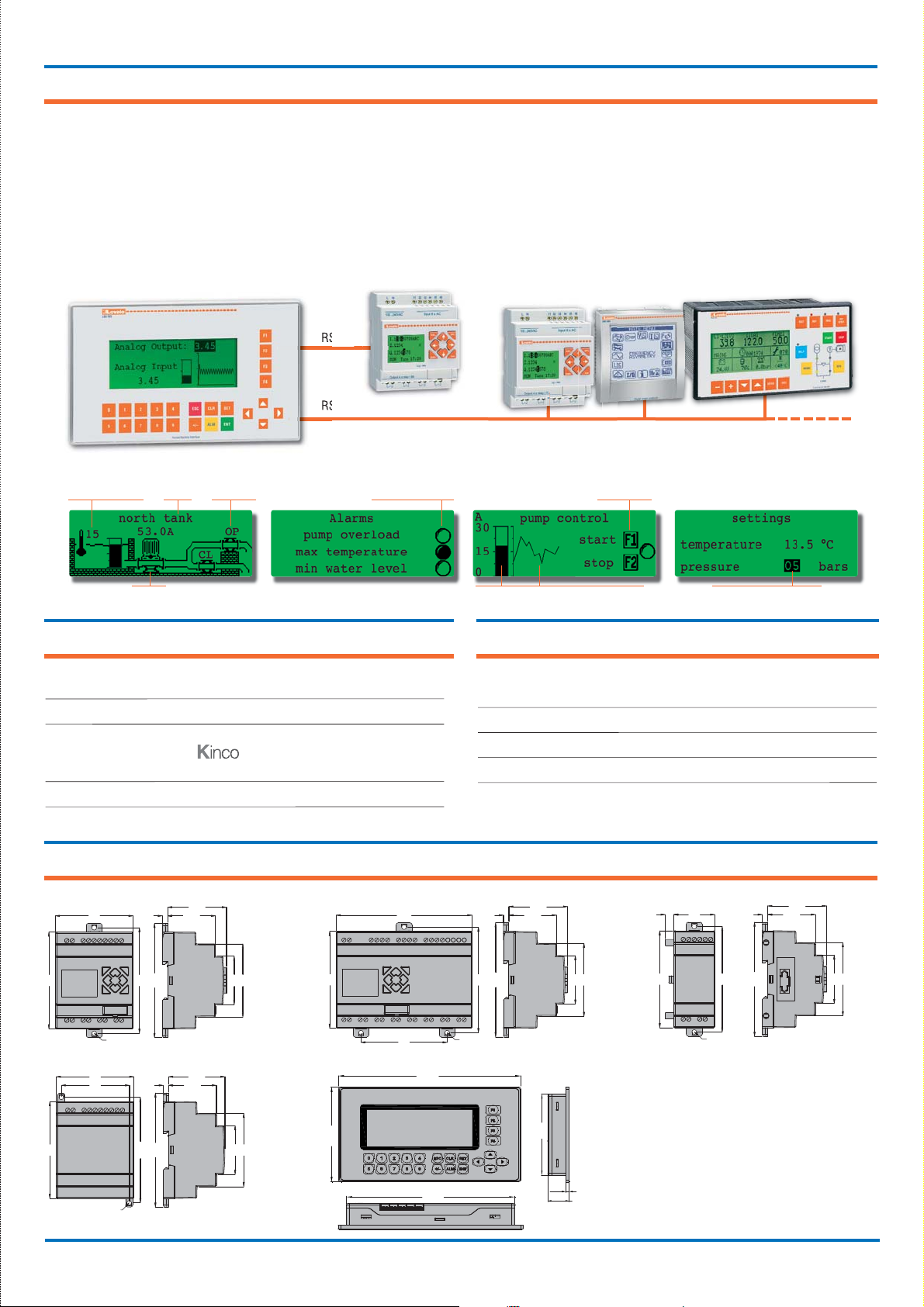
HMI operator panel LRX P01
LRX P01 is an HMI operator panel,
used with many types of PLCs or other
intelligent controllers equipped with
communication port.
By using the HMI, the values of both
PLC inner registers and relay status
can be monitored and changed with
Read numerical
values
Static
text
Dynamic
text
the keys or LEDs.
In this way, machinery and equipment
functioning results to be simple and
direct.
LRX P01 supports Modbus
®
protocol and different communication
methods can be chosen, such as
RS232
RS485
Read status (bits)
-RTU
RS232 and RS485.
The LRX SW P01 editor software
permits to make dedicated screens by
taking advantage of the graphic display
to view bitmaps, bar graphs and trend
lines.
Commands
Images Display bar graphs and trend lines
Characteristics
• 24VDC power supply
• Backlight graphic 192x64 pixel LCD
• RS232 communication port:
- Direct connection to using LRX COO
- Connection to other devices using a serial cable
• RS485 communication port
• LRX SW P01 editor software.
Dimensions [mm]
LRD10... - LRD12...
72
90
Ø4.5
LRX1V3 D024
72
60
98
54.6
44.35
68
106
52.3
44.35
45
LRD20...
90
LRX P01
Write numerical values
Functions
• Send commands
• Read status
• Provide static and dynamic texts
• Write variables
• Read variables: numerical value, bar graph and trend line.
126
98
80
Ø4.5
179.5
54.6
44.35
68
106
45
LRE...
8 38
90
98
Ø4.5
54.3
44.35
45
106
68
90
Ø4.5
97.9
106
68
45
101.5
163.5
85.5
5.5
33
Page 7
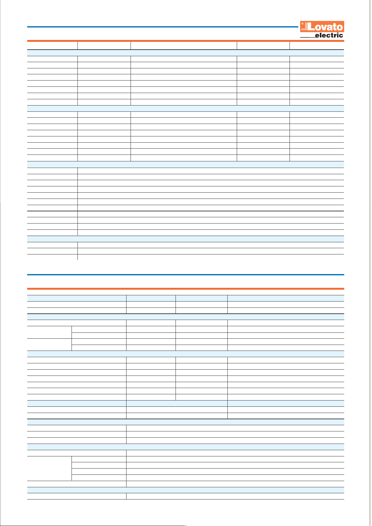
How to order
Order code Power supply INPUTS OUTPUTS MAX DIGITAL I/O
Base modules Base + expansions
LRD12RD024 24VDC 6 digital + 2 digital/analog 4 Relay 12 + 24
LRD12TD024 24VDC 6 digital + 2 digital/analog 4 Transistor 12 + 24
LRD20RD024 24VDC 8 digital + 4 digital/analog 8 Relay 20 + 24
LRD20TD024 24VDC 8 digital + 4 digital/analog 8 Transistor 20 + 24
LRD10RA240 100-240VAC 6 digital 4 Relay 10 + 24
LRD20RA240 100-240VAC 12 digital 8 Relay 20 + 24
LRD12RA024 24VAC 8 digital 4 Relay 12 + 24
LRD20RA024 24VAC 12 digital 8 Relay 20 + 24
Expansion and communication modules
LRE02AD024 24VDC –– 2 analogic ––
LRE04AD024 24VDC 4 analog –– ––
LRE04PD024 24VDC 4 PT100 –– ––
LRE08RD024 24VDC 4 digital 4 Relay ––
LRE08TD024 24VDC 4 digital 4 Transistor ––
LRE08RA240 100-240VAC 4 digital 4 Relay ––
LRE08RA024 24VAC 4 digital 4 Relay ––
LREP00 24VDC RS485 Modbus®-RTU slave communication unit –– ––
Accessories
LRX M00 Program backup memory unit
LRX C00 PC - LRD connecting cable (1.5m long)
LRX SW Programming and supervision software and user’s manual (CD-ROM) for LRDs
LRX 1V3 D024 Power supply unit, 100-240VAC/24VDC, 1.3A
LRX D00 User’s manual in Italian (hard copy)
LRX D01 User’s manual in English (hard copy)
LRX D02 User’s manual in Spanish (hard copy)
LRX D03 User’s manual in French (hard copy)
LRX P01 HMI operator panel 24VDC, interface RS232 and RS485 (Modbus®-RTU Master)
LRX C02 PC - LRX P01 connecting cable
LRX SW P01 Editor software and user’s manual (CD-ROM) for LRX P01 HMI
Starter kits
LRDKIT 12R D024 LRD starter kit complete with LRD12R D024 micro PLC, LRX SW software and LRX C00 cable
LRDKIT 12R A024 LRD starter kit complete with LRD12R A024 micro PLC, LRX SW software and LRX C00 cable
LRDKIT 10R A240 LRD starter kit complete with LRD10R A240 micro PLC, LRX SW software and LRX C00 cable
Techanical characteristics
Auxiliary power supply LRD…D024 LRD…A024 LRD…A240
Rated voltage Ue (frequency) 24VDC 24VAC (50-60Hz) 100-240VAC (50-60Hz)
Operating range 20.4-28.8VDC 20.4-28.8VDC (47-63Hz) 85-264VAC (47-63Hz)
Digital inputs
Rated voltage 24VDC 24VAC (50-60Hz) 100-240VAC (50-60Hz)
Input voltage
Delay time
Analog inputs (for 24VDC versions only)
Input signal range 0-10V - Display resolution 0.01V - Conversion 8 bits - Current consumption at 10VDC <0.17mA - Input resistance <1kΩ --
Maximum overload 28VDC - Maximum cable length ≤ 30m screened - -
Digital outputs LRD…R… / LRE08R… LRD…T… / LRE08T…
Type of output / Rated current Ith Relay / 8A Transistor / 0.3A 24VDC
Applied voltage 12-24VAC / 12-125VDC 10-28.8VDC
Ambient conditions
Temperature - operation / storage -20…+55°C / -40…+70°C
Relative humidity 20-90% with no condensation
Maximum pollution degree 2
Housing
Version Modular for mounting on 35mm (IEC/EN 60715) DIN rail or screw fixing (M4x20mm)
Connections
Degree of protection IP20
Certifications and compliance
Certifications obtained / Compliant with standards cULus / IEC/EN 61131-2
State 0 <5VDC/<0.625mA <6VDC/<0.85mA <40VAC/<0.28mA (LRD10R A240); <0.15mA (LRD20R A240)
State 1 >15VDC/>1.875mA >14VDC/>3mA >79VAC/>0.41mA
0 to 1
1 to 0
Type of terminal Screw
Conductor section 0.14-2.5mm
Tightening torque 0.6Nm / 0.4lbft
Maximum cable length ≤100m
3ms (0.5ms high speed)
5ms (0.3ms high speed)
90ms 50-45ms (Ue=120VAC); 22-18ms (Ue=240VAC)
90ms 50-45ms (Ue=120VAC); 90-85ms (Ue=240VAC)
2
/ 26-14AWG
Page 8
new
2011
Switch disconnectors
16A to 1600A
Planet Switch
Motor protection circuit
breakers
I
N
O
Switch disconnectors
F
F
O
0
Contactors
Motor protection relays
Electromechanical starters
Control and signalling units
Limit, micro and foot switches
Rotary cam swithces
)
7
(
3
1
5
13
)
7
(
3
1
5
3
0
1
1
5.
2
)
N
8
(
C
4
1
1
6
A
4
2
V
4
2
A
2
z
H
0
6
/
0
5
r
cto
a
t
n
o
c
r
a
l
u
od
M
2
Modular contactors
Time relays
Fuse holders
Digital multimeters
and analyzers
Energy meters
Automatic transfer switch
controllers
Planet DinPlanet Logic
Protection relays
Level control relays
1
R
,
0
,
0
,
0
,
0
E
RTH
KAG
E
A
A
L
E
A
,
L
R
0
E
,
0
0
c
e
s
(
t
,
0
0
T
E
S
I
R
T
RE
,
1
2
1
O
a
s
n
e
e
r
m
,
2
x
t
,
0
x0,
n
A
n (
I
I
,
2
0
uto
s
e
e
r
1
a
x
t
a
n
s
e
e
r
m
x
T
t
x
n
I
S
E
x0,
T
n
I
x
1
n
I
uto
s
e
e
r
a
1
x
t
NCT
U
I
O
F
x
n
I
a
n
s
e
e
r
m
x
x
1
1
n
n
I
I
x
t
AL
C
SET
E
T
I
n S
N
I
x0,
n
I
s
uto
e
e
r
a
1
x
t
x
n
I
a
s
n
e
e
r
m
x
x
1
n
n
I
I
x
t
x0,
n
I
s
uto
e
e
r
1
a
x
t
x
n
I
x
1
n
I
x0,
n
I
Earth leakage relays
Fuse holders
Metering instruments and current
transformers
Soft starters
N
U
R
N
O
M
P
O
T
S
AC motor drives
T
N
E
Automatic power factor
controllers
D
E
G
R
A
H
C
RY
E
T
T
A
B
N
C
I
O
T
R
A
E
M
W
O
O
P
E
UT
G
A
W
L
ATTERY VO
G
A
O
T
R
B
L
A
W
S
E BL
ATTERY
U
O
CH
F
B
M
T
O
ONNECTE
ATTERY
N
C
B
R
A
L
L
VERT
I
RY PO
R
TE
Y
E
A
A
IN
T
BAT
C
LAR
A
S
E
T
E
I
N
L
I
A
L
M
H CONTRO
UT
T
ANS
FER
W
LE
C
O
I
R
T
S
C T
A
S
E
T
T
H
A
E
I
N
L
L
L
U
A
L
H
A
L
M
L
O
L
F
O
F
O
E
SE
R
O
ITH
DRAW
W
RI
T
O
F
O
O
E
U
W
T
A
NO
O
RED
0
D
P
7 LO
T. O
A
E
R
T
NO
E
NERAT
AD
0
O
8
R
G
A
A
O
L
E
G
0
MER
NCY ST
O
9
E
A
I
R
I
T
DRAW
H
T
W
I
H
L
E
U
W
0
C
A
4 LI
T
F
N
2 S
A
R
ONG
E
HASE SEQ
0
5 LI
P
N
1 W
A
R
E
ONG
0
HASE SEQ
6 LI
N
2 W
P
A
W
L
0
ATTERY VO
G
A
1 LO
T
B
A
H
L
0
ATTERY VO
G
A
2
T
HIG
B
A
I
E
H
L
0
W
U
C
A
3 LI
N
1 S
T
F
A
B
=
2V
- 3
1
=
4V
- 2.5
2
Automatic battery chargers
7
8
6
9
5
00
1
4
E
0
3
RG
FUSE 6,3A
CHA
BATTERY
I
BATTERY
+
ALARM OUT
_
50-60Hz
_
220-240V~
POWER
N
L
Automatic transfer switch
controllers
Micro PLCs
The products described in this publication are subject to be revised or improved at any moment. Catalogue descriptions and
details, such as technical and operational data, drawings, diagrams and instructions, etc., do not have any contractual value.
In addition, products should be installed and used by qualified personnel and in compliance with the regulations in force for
Switching power supplies
Expansion modules and
accessories
2
2
9
1
e
c
n
i
S
electrical systems in order to avoid damages and safety hazards.
Switching power supplies
100% electricity
www.LovatoElectric.com
LOVATO ELECTRIC S.P.A.
CONTROL SOLUTIONS FOR INDUSTRY
VIA DON E. MAZZA, 12 - 24020 GORLE (BERGAMO) ITALY
+39 035 4282111 Fax +39 035 4282200
Tel .
E
-mail: [email protected]
LOVATO Electric offices in the world
United Kingdom
LOVATO ELECTRIC LTD
Tel. +44 8458 110023
www.Lovato.co.uk
Czech Republic
LOVATO SPOL. S.R.O.
Tel. +420 382 265482
www.LovatoElectric.cz
Germany
DELTEC LOVATO GmbH
Tel. +49 7237 1733
www.DeltecLovato.de
USA
LOVATO ELECTRIC INC
Tel. +1 757 545 4700
www.LovatoUsa.com
Sales Department: Tel . +39 035 4282354 - Fax +39 035 4282400
Spain
LOVATO ELECTRIC S.L.U.
Tel. +34 93 7812016
www.LovatoElectric.es
Canada
LOVATO ELECTRIC
CORPORATION
Tel. +1 450 681 9200
www.Lovato.ca
Present in over 100 countries
Poland
LOVATO ELECTRIC SP. Z O.O.
Tel. +48 71 7979010
www.LovatoElectric.pl
Mexico
LOVATO ELECTRIC
DE MEXICO, S.A. DE C.V.
Tel. +52 555 3415662
www.LovatoElectric.com.mx
PD09 GB 10 11
 Loading...