

Page 1
DIGITAL MULTIMETER
GB
Operating manual
LOVATO ELECTRIC S.P.A.
24020 GORLE (BERGAMO) ITALIA
VIA DON E. MAZZA, 12
TEL. 035 4282111
FAX (Nazionale): 035 4282200
FAX (International): +39 035 4282400
E-mail info@
Web www.
I422 GB I 10 17 31100212
WARNING!
– Carefully read the manual before the installation or use.
– This equipment is to be installed by qualified personnel, complying to current standards, to avoid
damages or safety hazards.
– Before any maintenance operation on the device, remove all the voltages from measuring and supply inputs and short-
circuit the CT input terminals.
– The manufacturer cannot be held responsible for electrical safety in case of improper use of the equipment.
– Products illustrated herein are subject to alteration and changes without prior notice. Technical data and descriptions
in the documentation are accurate, to the best of our knowledge, but no liabilities for errors, omissions or
contingencies arising there from are accepted.
– A circuit breaker must be included in the electrical installation of the building. It must be installed close by the
equipment and within easy reach of the operator. It must be marked as the disconnecting device of the equipment:
IEC /EN 61010-1 § 6.11.2.
– Clean the instrument with a soft dry cloth; do not use abrasives, liquid detergents or solvents.
ATTENTION !
– Lire attentivement le manuel avant toute utilisation et installation.
– Ces appareils doivent être installés par un personnel qualifié, conformément aux normes en vigueur en
matière d'installations, afin d'éviter de causer des dommages à des personnes ou choses.
– Avant toute intervention sur l'instrument, mettre les entrées de mesure et d'alimentation hors tension et court-circuiter
les transformateurs de courant.
– Le constructeur n'assume aucune responsabilité quant à la sécurité électrique en cas d'utilisation impropre du
dispositif.
– Les produits décrits dans ce document sont susceptibles d'évoluer ou de subir des modifications à n'importe quel
moment. Les descriptions et caractéristiques techniques du catalogue ne peuvent donc avoir aucune valeur
contractuelle.
– Un interrupteur ou disjoncteur doit être inclus dans l'installation électrique du bâtiment. Celui-ci doit se trouver tout
près de l'appareil et l'opérateur doit pouvoir y accéder facilement. Il doit être marqué comme le dispositif
d'interruption de l'appareil : IEC/ EN 61010-1 § 6.11.2.
– Nettoyer l'instrument avec un chiffon doux, ne pas utiliser de produits abrasifs, détergents liquides ou solvants.
ACHTUNG!
– Dieses Handbuch vor Gebrauch und Installation aufmerksam lesen.
– Zur Vermeidung von Personen- und Sachschäden dürfen diese Geräte nur von qualifiziertem
Fachpersonal und unter Befolgung der einschlägigen Vorschriften installiert werden.
– Vor jedem Eingriff am Instrument die Spannungszufuhr zu den Messeingängen trennen und die Stromwandler
kurzschlieβen.
– Bei zweckwidrigem Gebrauch der Vorrichtung übernimmt der Hersteller keine Haftung für die elektrische Sicherheit.
– Die in dieser Broschüre beschriebenen Produkte können jederzeit weiterentwickelt und geändert werden. Die im
Katalog enthaltenen Beschreibungen und Daten sind daher unverbindlich und ohne Gewähr.
– In die elektrische Anlage des Gebäudes ist ein Ausschalter oder Trennschalter einzubauen. Dieser muss sich in
unmittelbarer Nähe des Geräts befinden und vom Bediener leicht zugänglich sein. Er muss als Trennvorrichtung für das
Gerät gekennzeichnet sein: IEC/ EN 61010-1 § 6.11.2.
– Das Instrument mit einem weichen Tuch reinigen, keine Scheuermittel, Flüssigreiniger oder Lösungsmittel verwenden.
L
ovatoElectric.com
L
ovatoElectric.com
DMG100 – DMG110
G
B
ATTENZIONE!
– Leggere attentamente il manuale prima dell’utilizzo e l’installazione.
– Questi apparecchi devono essere installati da personale qualificato, nel rispetto delle vigenti normative
impiantistiche, allo scopo di evitare danni a persone o cose.
– Prima di qualsiasi intervento sullo strumento, togliere tensione dagli ingressi di misura e di alimentazione e
cortocircuitare i trasformatori di corrente.
– Il costruttore non si assume responsabilità in merito alla sicurezza elettrica in caso di utilizzo improprio del dispositivo.
– I prodotti descritti in questo documento sono suscettibili in qualsiasi momento di evoluzioni o di modifiche. Le
descrizioni ed i dati a catalogo non possono pertanto avere alcun valore contrattuale.
– Un interruttore o disgiuntore va compreso nell’impianto elettrico dell’edificio. Esso deve trovarsi in stretta vicinanza
dell’apparecchio ed essere facilmente raggiungibile da parte dell’operatore. Deve essere marchiato come il dispositivo
di interruzione dell’apparecchio: IEC/ EN 61010-1 § 6.11.2.
– Pulire lo strumento con panno morbido, non usare prodotti abrasivi, detergenti liquidi o solventi.
UWAGA!
– Przed użyciem i instalacją urządzenia należy uważnie przeczytać niniejszą instrukcję.
– W celu uniknięcia obrażeń osób lub uszkodzenia mienia tego typu urządzenia muszą być instalowane przez
wykwalifikowany personel, zgodnie z obowiązującymi przepisami.
– Przed rozpoczęciem jakichkolwiek prac na urządzeniu należy odłączyć napięcie od wejść pomiarowych i zasilania oraz zewrzeć
zaciski przekładnika prądowego.
– Producent nie przyjmuje na siebie odpowiedzialności za bezpieczeństwo elektryczne w przypadku niewłaściwego użytkowania
urządzenia.
– Produkty opisane w niniejszym dokumencie mogą być w każdej chwili udoskonalone lub zmodyfikowane. Opisy oraz dane
katalogowe nie mogą mieć w związku z tym żadnej wartości umownej.
– W instalacji elektrycznej budynku należy uwzględnić przełącznik lub wyłącznik automatyczny. Powinien on znajdować się w
bliskim sąsiedztwie urządzenia i być łatwo osiągalny przez operatora. Musi być oznaczony jako urządzenie służące do
wyłączania urządzenia: IEC/ EN 61010-1 § 6.11.2.
– Urządzenie należy czyścić miękką szmatką, nie stosować środkow ściernych, płynnych detergentow lub rozpuszczalnikow.
警告
•
安装或使用前︐
•
本
•
•
•
•
建筑物
•
的
断开所
︐
︒
︐以避免造
有
IEC /EN 61010-1 § 6.11.2
成
端子的
︒
CT
︐并短
接
︒
ADVERTENCIA
– Leer atentamente el manual antes de instalar y utilizar el regulador.
– Este dispositivo debe ser instalado por personal cualificado conforme a la normativa de instalación
vigente a fin de evitar daños personales o materiales.
– Antes de realizar cualquier operación en el dispositivo, desconectar la corriente de las entradas de alimentación y
medida, y cortocircuitar los transformadores de corriente.
– El fabricante no se responsabilizará de la seguridad eléctrica en caso de que el dispositivo no se utilice de forma
adecuada.
– Los productos descritos en este documento se pueden actualizar o modificar en cualquier momento. Por consiguiente,
las descripciones y los datos técnicos aquí contenidos no tienen valor contractual.
– La instalación eléctrica del edificio debe disponer de un interruptor o disyuntor. Éste debe encontrarse cerca del
dispositivo, en un lugar al que el usuario pueda acceder con facilidad. Además, debe llevar el mismo marcado que el
interruptor del dispositivo (IEC/ EN 61010-1 § 6.11.2).
– Limpiar el dispositivo con un trapo suave; no utilizar productos abrasivos, detergentes líquidos ni disolventes.
UPOZORNĚNÍ
– Návod se pozorně pročtěte, než začnete regulátor instalovat a používat.
– Tato zařízení smí instalovat kvalifikovaní pracovníci v souladu s platnými předpisy a normami pro předcházení
úrazů osob či poškození věcí.
– Před jakýmkoli zásahem do přístroje odpojte měřicí a napájecí vstupy od napětí a zkratujte transformátory proudu.
– Výrobce nenese odpovědnost za elektrickou bezpečnost v případě nevhodného používání regulátoru.
– Výrobky popsané v tomto dokumentu mohou kdykoli projít úpravami či dalším vývojem. Popisy a údaje uvedené v katalogu
nemají proto žádnou smluvní hodnotu.
– Spínač či odpojovač je nutno zabudovat do elektrického rozvodu v budově. Musejí být nainstalované v těsné blízkosti přístroje a
snadno dostupné pracovníku obsluhy. Je nutno ho označit jako vypínací zařízení přístroje: IEC/ EN 61010-1 § 6.11.2.
– Přístroj čistěte měkkou utěrkou, nepoužívejte abrazivní produkty, tekutá čistidla či rozpouštědla.
AVERTIZARE!
– Citiţi cu atenţie manualul înainte de instalare sau utilizare.
– Acest echipament va fi instalat de personal calificat, în conformitate cu standardele actuale, pentru a evita
deteriorări sau pericolele.
– Înainte de efectuarea oricărei operaţiuni de întreţinere asupra dispozitivului, îndepărtaţi toate tensiunile de la intrările de
măsurare şi de alimentare şi scurtcircuitaţi bornele de intrare CT.
– Produsele ilustrate în prezentul sunt supuse modificărilor şi schimbărilor fără notificare anterioară.
– Datele tehnice şi descrierile din documentaţie sunt precise, în măsura cunoştinţelor noastre, dar nu se acceptă nicio răspundere
pentru erorile, omiterile sau evenimentele neprevăzute care apar ca urmare a acestora.
– Trebuie inclus un disjunctor în instalaţia electrică a clădirii. Acesta trebuie instalat aproape de echipament şi într-o zonă uşor
accesibilă operatorului. Acesta trebuie marcat ca fiind dispozitivul de deconectare al echipamentului: IEC/EN 61010-1 § 6.11.2.
– Curăţaţi instrumentul cu un material textil moale şi uscat; nu utilizaţi substanţe abrazive, detergenţi lichizi sau solvenţi.
ПРЕДУПРЕЖДЕНИЕ!
– Прежде чем приступать к монтажу или эксплуатации устройства, внимательно ознакомьтесь с одержанием
– Во избежание травм или материального ущерба монтаж должен существляться только квалифицированным персоналом
– Перед проведением любых работ по техническому обслуживанию устройства необходимо обесточить все
– Производитель не несет ответственность за обеспечение электробезопасности в случае ненадлежащего использования
– Изделия, описанные в настоящем документе, в любой момент могут подвергнуться изменениям или
– Электрическая сеть здания должна быть оснащена автоматическим выключателем, который должен быть расположен
– Очистку устройства производить с помощью мягкой сухой ткани, без применения абразивных материалов, жидких
DİKKAT!
– Montaj ve kullanımdan önce bu el kitabını dikkatlice okuyunuz.
– Bu aparatlar kişilere veya nesnelere zarar verme ihtimaline karşı yürürlükte olan sistem kurma normlarına göre
– Aparata (cihaz) herhangi bir müdahalede bulunmadan önce ölçüm girişlerindeki gerilimi kesip akım transformatörlerinede kısa
– Üretici aparatın hatalı kullanımından kaynaklanan elektriksel güvenliğe ait sorumluluk kabul etmez.
– Bu dokümanda tarif edilen ürünler her an evrimlere veya değişimlere açıktır. Bu sebeple katalogdaki tarif ve değerler herhangi bir
– Binanın elektrik sisteminde bir anahtar veya şalter bulunmalıdır. Bu anahtar veya şalter operatörün kolaylıkla ulaşabileceği yakın
– Aparatı (cihaz) sıvı deterjan veya solvent kullanarak yumuşak bir bez ile siliniz aşındırıcı temizlik ürünleri kullanmayınız.
настоящего руководства.
в соответствии с действующими нормативами.
измерительные и питающие входные контакты, а также замкнуть накоротко входные контакты трансформатора тока (ТТ).
устройства.
усовершенствованиям. Поэтому каталожные данные и описания не могут рассматриваться как действительные с точки
зрения контрактов
вблизи оборудования в пределах доступа оператора. Автоматический выключатель должен быть промаркирован как
отключающее устройство оборудования: IEC /EN 61010-1 § 6.11.2.
моющих средств или растворителей.
kalifiye personel tarafından monte edilmelidirler
devre yaptırınız.
bağlayıcı değeri haiz değildir.
bir yerde olmalıdır. Aparatı (cihaz) devreden çıkartma görevi yapan bu anahtar veya şalterin markası: IEC/ EN 61010-1 § 6.11.2.
1
Page 2
INDEX Page
Introduction . . . . . . . . . . . . . . . . . . . . . . . . . . . . . . . . . . . . . . . . . . . . . . . . . . . . . . . . . . . . . . . . . . . . . . . . . . . . . . . . . . . . . . . . . . . . . . . . . . . . . . . . . . . . . . . . . . . . . . . . . . . . . . . . . . . . . . . . . . . . . . . . . . . . . . . . . . . . . 2
Description . . . . . . . . . . . . . . . . . . . . . . . . . . . . . . . . . . . . . . . . . . . . . . . . . . . . . . . . . . . . . . . . . . . . . . . . . . . . . . . . . . . . . . . . . . . . . . . . . . . . . . . . . . . . . . . . . . . . . . . . . . . . . . . . . . . . . . . . . . . . . . . . . . . . . . . . . . . . . 2
Front button functions . . . . . . . . . . . . . . . . . . . . . . . . . . . . . . . . . . . . . . . . . . . . . . . . . . . . . . . . . . . . . . . . . . . . . . . . . . . . . . . . . . . . . . . . . . . . . . . . . . . . . . . . . . . . . . . . . . . . . . . . . . . . . . . . . . . . . . . . . . . . . . . . . . . . . 2
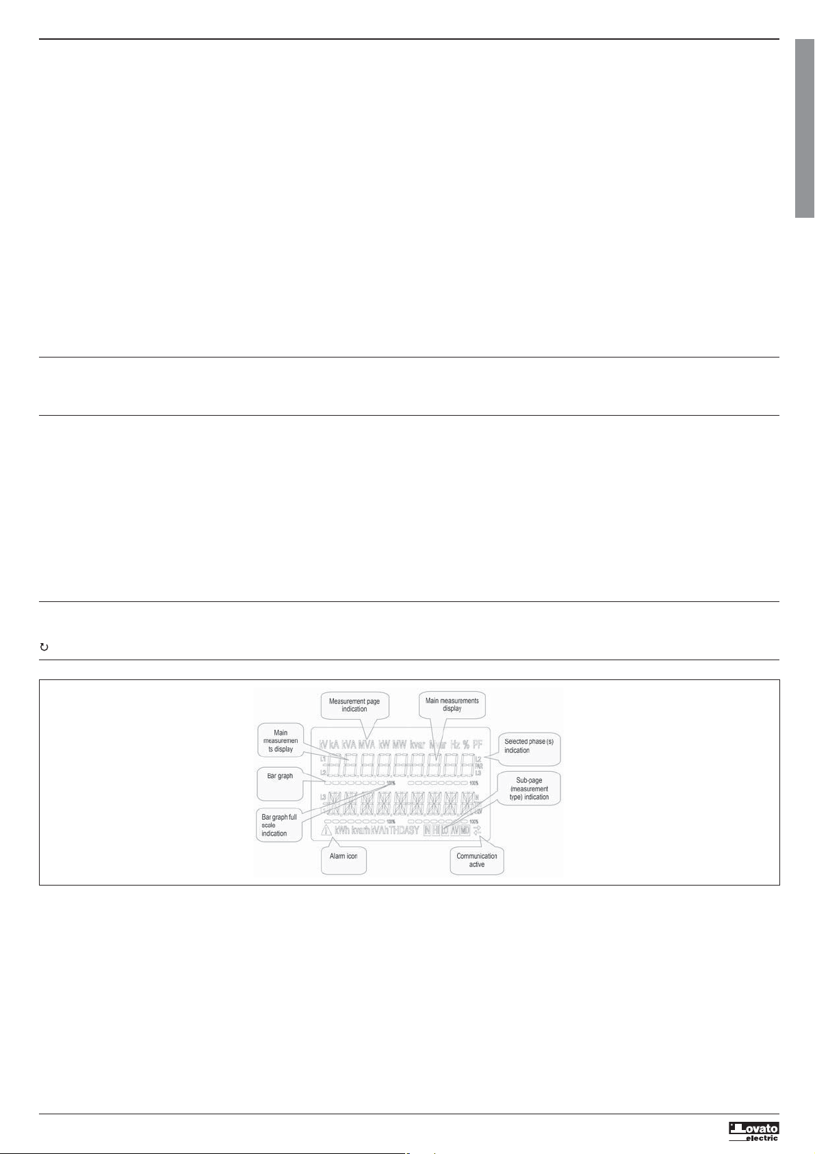
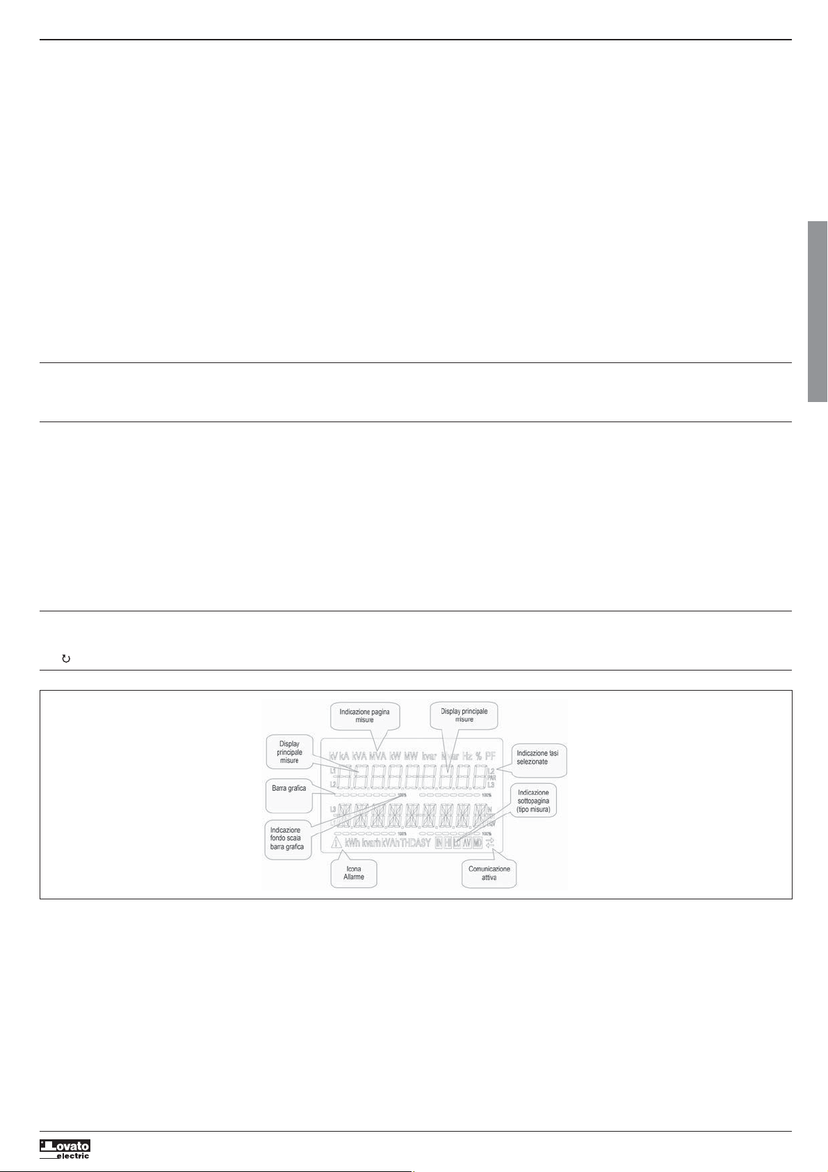
Display indications. . . . . . . . . . . . . . . . . . . . . . . . . . . . . . . . . . . . . . . . . . . . . . . . . . . . . . . . . . . . . . . . . . . . . . . . . . . . . . . . . . . . . . . . . . . . . . . . . . . . . . . . . . . . . . . . . . . . . . . . . . . . . . . . . . . . . . . . . . . . . . . . . . . . . . . . 2
Displaying measurements . . . . . . . . . . . . . . . . . . . . . . . . . . . . . . . . . . . . . . . . . . . . . . . . . . . . . . . . . . . . . . . . . . . . . . . . . . . . . . . . . . . . . . . . . . . . . . . . . . . . . . . . . . . . . . . . . . . . . . . . . . . . . . . . . . . . . . . . . . . . . . . . . . 3
Table of display pages . . . . . . . . . . . . . . . . . . . . . . . . . . . . . . . . . . . . . . . . . . . . . . . . . . . . . . . . . . . . . . . . . . . . . . . . . . . . . . . . . . . . . . . . . . . . . . . . . . . . . . . . . . . . . . . . . . . . . . . . . . . . . . . . . . . . . . . . . . . . . . . . . . . . . 3
Navigating between the display pages . . . . . . . . . . . . . . . . . . . . . . . . . . . . . . . . . . . . . . . . . . . . . . . . . . . . . . . . . . . . . . . . . . . . . . . . . . . . . . . . . . . . . . . . . . . . . . . . . . . . . . . . . . . . . . . . . . . . . . . . . . . . . . . . . . . . . . . . . 4
Harmonic analysis indication . . . . . . . . . . . . . . . . . . . . . . . . . . . . . . . . . . . . . . . . . . . . . . . . . . . . . . . . . . . . . . . . . . . . . . . . . . . . . . . . . . . . . . . . . . . . . . . . . . . . . . . . . . . . . . . . . . . . . . . . . . . . . . . . . . . . . . . . . . . . . . . . 5
Energy meter indication . . . . . . . . . . . . . . . . . . . . . . . . . . . . . . . . . . . . . . . . . . . . . . . . . . . . . . . . . . . . . . . . . . . . . . . . . . . . . . . . . . . . . . . . . . . . . . . . . . . . . . . . . . . . . . . . . . . . . . . . . . . . . . . . . . . . . . . . . . . . . . . . . . . . 5
Hour counter indication . . . . . . . . . . . . . . . . . . . . . . . . . . . . . . . . . . . . . . . . . . . . . . . . . . . . . . . . . . . . . . . . . . . . . . . . . . . . . . . . . . . . . . . . . . . . . . . . . . . . . . . . . . . . . . . . . . . . . . . . . . . . . . . . . . . . . . . . . . . . . . . . . . . . 5
Limit threshold status indication (LIMn) . . . . . . . . . . . . . . . . . . . . . . . . . . . . . . . . . . . . . . . . . . . . . . . . . . . . . . . . . . . . . . . . . . . . . . . . . . . . . . . . . . . . . . . . . . . . . . . . . . . . . . . . . . . . . . . . . . . . . . . . . . . . . . . . . . . . . . . 5
Alarm indication. . . . . . . . . . . . . . . . . . . . . . . . . . . . . . . . . . . . . . . . . . . . . . . . . . . . . . . . . . . . . . . . . . . . . . . . . . . . . . . . . . . . . . . . . . . . . . . . . . . . . . . . . . . . . . . . . . . . . . . . . . . . . . . . . . . . . . . . . . . . . . . . . . . . . . . . . . 6
I422 GB I 10 17 31100212
Main menu . . . . . . . . . . . . . . . . . . . . . . . . . . . . . . . . . . . . . . . . . . . . . . . . . . . . . . . . . . . . . . . . . . . . . . . . . . . . . . . . . . . . . . . . . . . . . . . . . . . . . . . . . . . . . . . . . . . . . . . . . . . . . . . . . . . . . . . . . . . . . . . . . . . . . . . . . . . . . 6
Setting parameters (set-up) from the front panel . . . . . . . . . . . . . . . . . . . . . . . . . . . . . . . . . . . . . . . . . . . . . . . . . . . . . . . . . . . . . . . . . . . . . . . . . . . . . . . . . . . . . . . . . . . . . . . . . . . . . . . . . . . . . . . . . . . . . . . . . . . . . . . . 6
Parameter table . . . . . . . . . . . . . . . . . . . . . . . . . . . . . . . . . . . . . . . . . . . . . . . . . . . . . . . . . . . . . . . . . . . . . . . . . . . . . . . . . . . . . . . . . . . . . . . . . . . . . . . . . . . . . . . . . . . . . . . . . . . . . . . . . . . . . . . . . . . . . . . . . . . . . . . . . . 7
Commands menu . . . . . . . . . . . . . . . . . . . . . . . . . . . . . . . . . . . . . . . . . . . . . . . . . . . . . . . . . . . . . . . . . . . . . . . . . . . . . . . . . . . . . . . . . . . . . . . . . . . . . . . . . . . . . . . . . . . . . . . . . . . . . . . . . . . . . . . . . . . . . . . . . . . . . . . . 10
Connection test . . . . . . . . . . . . . . . . . . . . . . . . . . . . . . . . . . . . . . . . . . . . . . . . . . . . . . . . . . . . . . . . . . . . . . . . . . . . . . . . . . . . . . . . . . . . . . . . . . . . . . . . . . . . . . . . . . . . . . . . . . . . . . . . . . . . . . . . . . . . . . . . . . . . . . . . . . 10
Connection schemes . . . . . . . . . . . . . . . . . . . . . . . . . . . . . . . . . . . . . . . . . . . . . . . . . . . . . . . . . . . . . . . . . . . . . . . . . . . . . . . . . . . . . . . . . . . . . . . . . . . . . . . . . . . . . . . . . . . . . . . . . . . . . . . . . . . . . . . . . . . . . . . . . . . . . . 11
Terminal layout. . . . . . . . . . . . . . . . . . . . . . . . . . . . . . . . . . . . . . . . . . . . . . . . . . . . . . . . . . . . . . . . . . . . . . . . . . . . . . . . . . . . . . . . . . . . . . . . . . . . . . . . . . . . . . . . . . . . . . . . . . . . . . . . . . . . . . . . . . . . . . . . . . . . . . . . . . . 12
Mechanical dimensions and panel cut-out (mm). . . . . . . . . . . . . . . . . . . . . . . . . . . . . . . . . . . . . . . . . . . . . . . . . . . . . . . . . . . . . . . . . . . . . . . . . . . . . . . . . . . . . . . . . . . . . . . . . . . . . . . . . . . . . . . . . . . . . . . . . . . . . . . . . 12
Technical specifications . . . . . . . . . . . . . . . . . . . . . . . . . . . . . . . . . . . . . . . . . . . . . . . . . . . . . . . . . . . . . . . . . . . . . . . . . . . . . . . . . . . . . . . . . . . . . . . . . . . . . . . . . . . . . . . . . . . . . . . . . . . . . . . . . . . . . . . . . . . . . . . . . . . . 13
Manual revision history . . . . . . . . . . . . . . . . . . . . . . . . . . . . . . . . . . . . . . . . . . . . . . . . . . . . . . . . . . . . . . . . . . . . . . . . . . . . . . . . . . . . . . . . . . . . . . . . . . . . . . . . . . . . . . . . . . . . . . . . . . . . . . . . . . . . . . . . . . . . . . . . . . . . 13
INTRODUCTION
DMG100 and DMG110 multimeters are designed to combine the utmost ease of use with a wide range of advanced functions. Despite the extremely limited dimensions of the modular housing (just 4 modules), the
multimeter features the same performance as a high-level device. The backlit LCD display permits a clear and intuitive user interface. The DMG110 also features an isolated RS-485 communication interface with
Modbus protocol to permit supervision.
DESCRIPTION
– Three-phase digital multimeter.
– 4U (72 mm) modular housing for DIN rail.
– Backlit LCD display.
– Versions:
• DMG100 - standard version.
• DMG110 - with built-in RS485 interface.
– 4 navigation buttons for functions and settings.
– High-accuracy true root mean square (TRMS) measurement.
– Vast range of available measurements, including voltage and current THD and harmonic analysis.
– Wide range auxiliary power supply (100–240 VAC).
– 2-level password protection for settings.
– Backup copy of original settings.
– Fitting does not require tools.
– Texts in 6 languages.
G
B
FRONT BUTTON FUNCTIONS
MENU button – Used to enter or exit the various display and set-up menus.
andbuttons – Used to scroll between screens, select from available options on the display and change (increase/decrease) settings.
button – Used to scroll sub-pages, confirm selected options and switch between display modes.
DISPLAY INDICATIONS
2
Page 3
DISPLAYING MEASUREMENTS
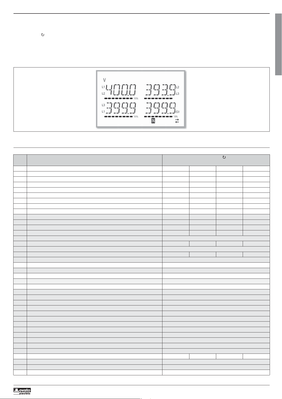
and buttons allow the measurement display pages to be scrolled one at a time. The current page can be recognized through the unit of measurement shown in the top part of the display.
– The
– Some measurements may not be displayed, depending on the programming and the connection for the device (for example, if programmed for a system without neutral, the measurements relating to neutral are
not displayed).
– For every page, the button permits access to sub-pages (for example, to display the maximum and minimum values recorded for the selected measurement).
– The sub-page displayed currently is indicated at the bottom right by one of the following icons:
•
IN = Instantaneous value – Current instantaneous value of the measurement, displayed by default every time the page is changed.
•
HI = Maximum instantaneous value – Highest value measured by the multimeter for the corresponding measurement. HIGH values are stored and preserved even in the absence of a power supply. They can be
reset through a dedicated command (see commands menu).
•
LO = Minimum instantaneous value – Lowest value measured by the multimeter from the moment voltage is applied. It is reset with the same command used for the HI values.
•
AV = Average value – Time-integrated (average) value of measurement. Permits display of a measurement with slow variations. See Integration menu.
•
MD = Maximum Demand – Peak integrated value (max demand). Remains stored in non-volatile memory and can be reset with a dedicated command.
I422 GB I 10 17 31100212
– The user can choose the page and sub-page that the display returns to automatically after a certain time has elapsed without the buttons being pressed.
– It is also possible to program the multimeter so that the display always remains that which was last selected.
– For the set-up of these functions, see the P02 – Utility menu.
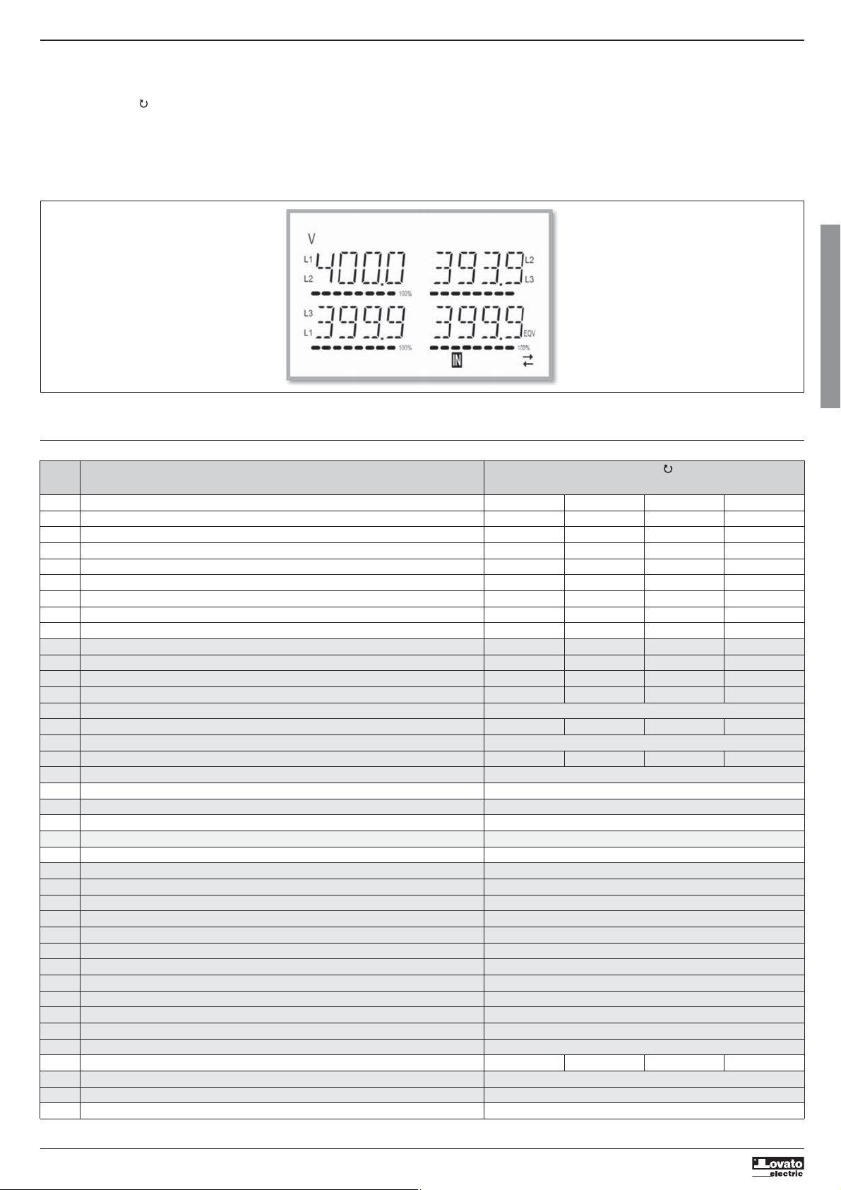
TABLE OF DISPLAY PAGES
Selection with
N° PAGE SUB PAGES
1 PHASE-TO-PHASE VOLTAGES - V(L1-L2), V(L2-L3), V(L3-L1), V(LL)EQV HI LO AV
2 PHASE-TO-NEUTRAL VOLTAGES - V(L1-N), V(L2-N), V(L3-N), V(L-N)EQV HI LO AV
3 PHASE AND NEUTRAL CURRENTS - I(L1), I(L2), I(L3), I(N) HI LO AV MD
4 ACTIVE POWER - P(L1), P(L2), P(L3), P(TOT) HI LO AV MD
5 REACTIVE POWER - Q(L1), Q(L2), Q(L3), Q(TOT) HI LO AV MD
6 APPARENT POWER - S(L1), S(L2), S(L3), S(TOT) HI LO AV MD
7 POWER FACTOR - PF(L1), PF(L2), PF(L3), PF(EQ) HI LO AV
8 ACTIVE POWER UNBALANCE - L1-L2, L2-L3, L3-L1 HI LO AV
9 FREQUENCY - Hz HI LO AV
10 ASYMMETRY ASY(VLL) HI LO AV
11 ASYMMETRY ASY(VLN) HI LO AV
12 ASYMMETRY ASY(I) HI LO AV
13 PH-PH VOLTAGE HARM. DISTORTION - THD-V(L1-L2), THD-V(L2-L3), THD-V(L3-L1) HI LO AV
14 VLL HARMONICS H2…H15
15 PH-N VOLTAGE HARMONIC DISTORTION - THD-V(L1),THD-V(L2),THD-V(L3) HI LO AV
16 VLN HARMONICS H2…H15
17 CURRENT HARMONIC DISTORTION - THD-I(L1), THD-I(L2) THD-I(L3) HI LO AV
18 CURRENT HARMONICS H2…H15
19 IMP. ACTIVE ENERGY METERS - kWh+(SYS) PAR - kWh+(SYS) TOT
20 EXP. ACTIVE ENERGY METERS - kWh-(SYS) PAR - kWh-(SYS) TOT
21 IMP. REACTIVE ENERGY METERS - kvarh+(SYS) PAR - kvarh+(SYS) TOT
22 EXP. REACTIVE ENERGY METERS - Kvarh-(SYS) PAR - Kvarh-(SYS) TOT
23 APPARENT ENERGY METERS - kvah(SYS) PAR - kvah(SYS) TOT
24 ENERGY METERS (L1) - kWh+(L1) PAR - kWh+(L1) TOT
25 ENERGY METERS (L2) - kWh+(L2) PAR - kWh+(L2) TOT
26 ENERGY METERS (L3) - kWh+(L3) PAR - kWh+(L3) TOT
27 ENERGY METERS (L1) - kWh-(L1) PAR - kWh-(L1) TOT
28 ENERGY METERS (L2) - kWh-(L2) PAR - kWh-(L2) TOT
29 ENERGY METERS (L3) - kWh-(L3) PAR - kWh-(L3) TOT
30 ENERGY METERS (L1) - kvarh+(L1) PAR - kvarh+(L1) TOT
31 ENERGY METERS (L2) - kvarh+(L2) PAR - kvarh+(L2) TOT
32 ENERGY METERS (L3) - kvarh+(L3) PAR - kvarh+(L3) TOT
33 ENERGY METERS (L1) - kvarh-(L1) PAR - kvarh-(L1) TOT
34 ENERGY METERS (L2) - kvarh-(L2) PAR - kvarh-(L2) TOT
35 ENERGY METERS (L3) - kvarh-(L3) PAR - kvarh-(L3) TOT
36 HOUR COUNTER - hhhhhh mm ss TOT PAR
37 LIMIT THRESHOLD - LIM1–LIM2–LIM3–LIM4
38 ALARMS - ALA1–ALA2–ALA3–ALA4
39 INFO-REVISION-SERIAL NO. - MODEL, REV SW, REV HW, SER. No.
Note: The pages highlighted in grey in the above table may not be displayed if the function or parameter that controls them is not enabled. For example, if no alarm is programmed, the corresponding page is not
displayed.
and Selection with
3
G
B
Page 4
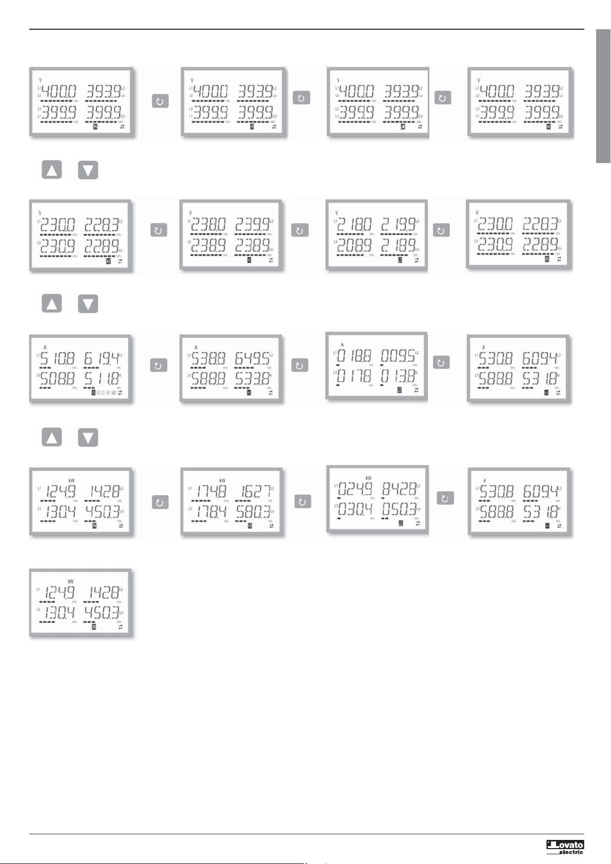
NAVIGATING BETWEEN THE DISPLAY PAGES
Phase-to-phase voltages
IN = Instantaneous value HI = Highest value LO = Lowest value AV = Average value
I422 GB I 10 17 31100212
Phase-to-neutral voltages
IN = Instantaneous value HI = Highest value LO = Lowest value AV = Average value
Phase and neutral currents
G
B
IN = Instantaneous value HI = Highest value LO = Lowest value AV = Average value
Active power phase and total
IN = Instantaneous value HI = Highest value LO = Lowest value AV = Average value
MD = Max Demand value
4
Page 5
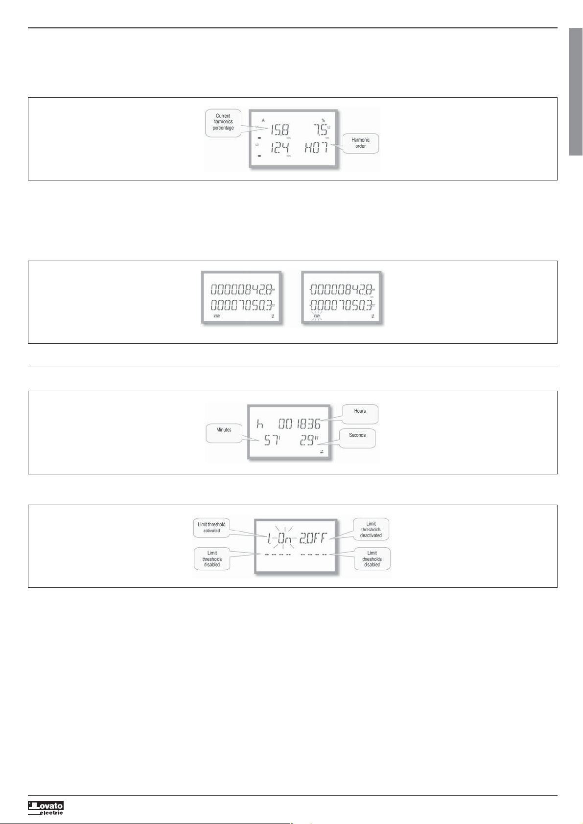
HARMONIC ANALYSIS INDICATION
– The DMG100-110 features harmonic phase analysis up to the 15th order for the following measurements:
•
phase-to-phase voltages
•
phase-to-neutral voltages
•
currents
– To activate harmonic analysis, parameter P02.12 must = THD/HAR.
– With P02.12 = THD, only the THD of the above measurements is displayed.
I422 GB I 10 17 31100212
ENERGY METER INDICATION
– There are five dedicated pages for energy meters.
•
Imported and exported active energy
•
Inductive or capacitive reactive energy
•
Apparent energy.
– Each page displays the total and partial value (can be reset from commands menu).
– If the unit of measurement is displayed continuously, it means that the meter is for imported energy (positive). Display of exported (negative) energies can be enabled as well by setting parameter P02.09 to ON.
These energies are highlighted by the flashing of the unit of measurement, and are displayed after the imported energies by pressing
.
G
B
Imported active energy Exported active energy
– If display of energy by individual phase is enabled (P02.10=ON), three independent additional pages, one per phase, will be displayed for each power, including total and partial energy.
HOUR COUNTER INDICATION
– If the hour counter is enabled (see menu P05), the DMG100-110 displays the hour counter page, with the format indicated in the figure:
LIMIT THRESHOLD STATUS INDICATION (LIMX)
– If the limit thresholds are enabled (see menu P08), the DMG100-110 displays the page, with the corresponding status and the format indicated in the figure:
– With limit threshold activated, the word ON flashes, while if it is deactivated the word OFF is constant. If no limit threshold is programmed, dashes are displayed.
5
Page 6
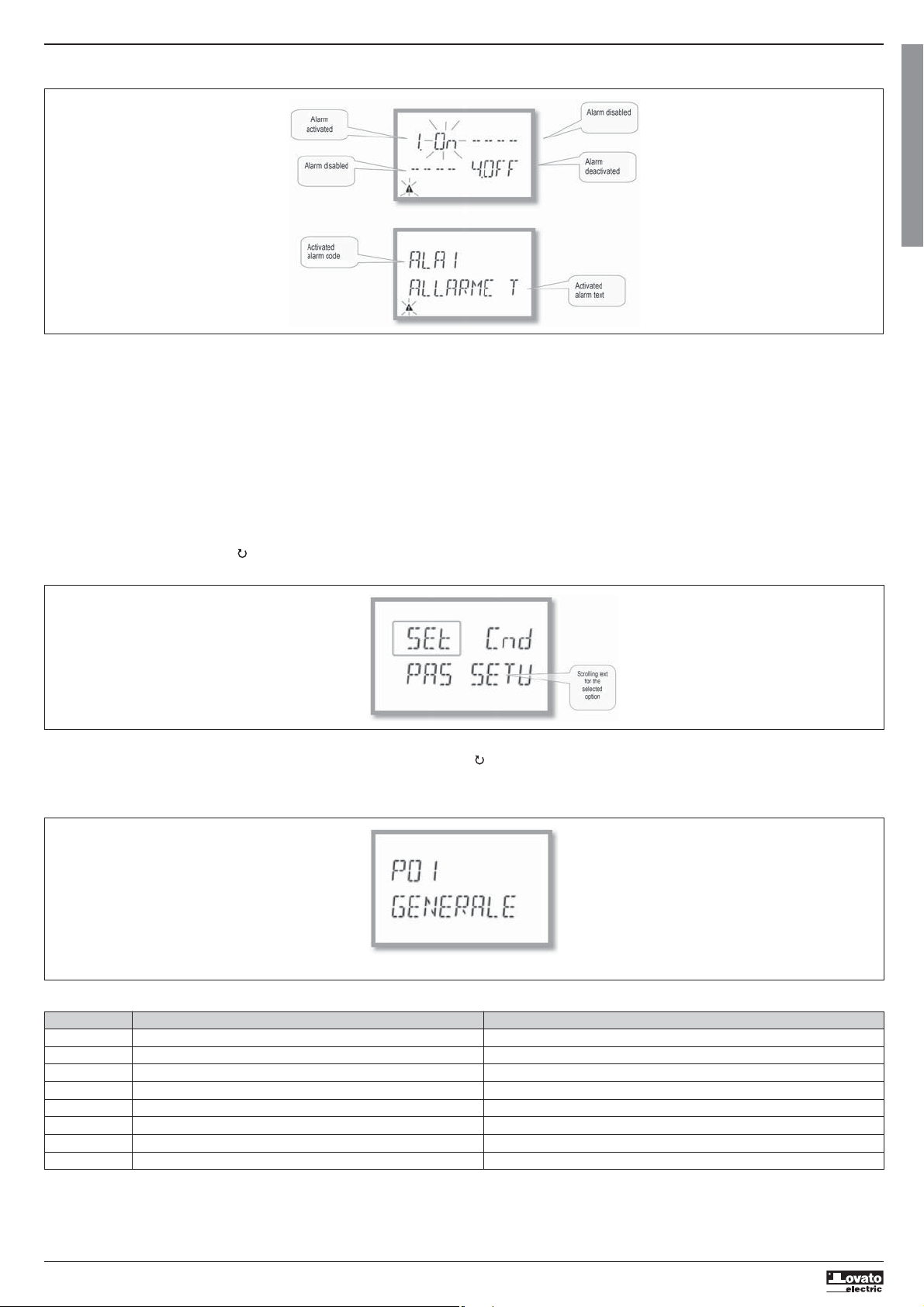
ALARM INDICATION
– If alarms are enabled (see menu P09), the DMG100-110 displays the page, with the corresponding status and the format indicated in the figure:
I422 GB I 10 17 31100212
– With Alarm activated, the word ON flashes with the triangle symbol, while if it is not activated the word OFF is constant.
– If no alarm is programmed, dashes are displayed. After about 3 s, the scrolling text of the alarm programmed in parameter P09.n.05 appears.
– With several alarms active, the text of the corresponding alarm alternates on the display.
– Dedicated parameter P02.14 for the utility menu can be used to make the display backlighting flash in the event of an alarm to highlight the presence of the fault.
– The alarm reset method depends on parameter P09.n.03. This determines whether it can be automatic, on the disappearance of the alarm conditions, or requires manual intervention through the commands menu
(C.07).
MAIN MENU
To access the main menu:
– Press the MENU button. The main menu is displayed (see figure), with the available options:
• SET – Access to the set-up menu
• CMD – Access to the commands menu
• PAS – Password entry
– The selected option flashes. Descriptive text for the selection scrolls in the alphanumeric display.
– If the password needs to be set, the menu opens with the option PAS already selected.
– Press
– To return to the measurement display, press MENU again.
to select the desired option, then to confirm.
G
B
SETTING PARAMETERS (SETUP) FROM THE FRONT PANEL
– From the standard measurement display, press MENU to call up the main menu, then select SET and press to access the settings menu.
– The display indicates the first menu level P.01 at the top left of the display, with selection 01 flashing.
– Select the desired menu (P.01, P.02, P.03) using the
– To exit and return to the measurement display, press MENU.
– The following menu lists the available menus:
Code MENU DESCRIPTION
P01 GENERAL Specifications of the system
P02 UTILITY Language, brightness, display, etc.
P03 PASSWORD Enablement of protected access
P04 INTEGRATION Measurement integration times
P05 HOUR COUNTER Enablement of hour counter
P07 COMMUNICATION Communication ports (DMG110)
P08 LIMIT THRESHOLDS (LIMn) Measurement thresholds
P09 ALARMS (ALAn) Alarm messages
buttons. During selection, the alphanumeric display scrolls a brief description of the currently selected menu.
Setup: menu selection
6
Page 7
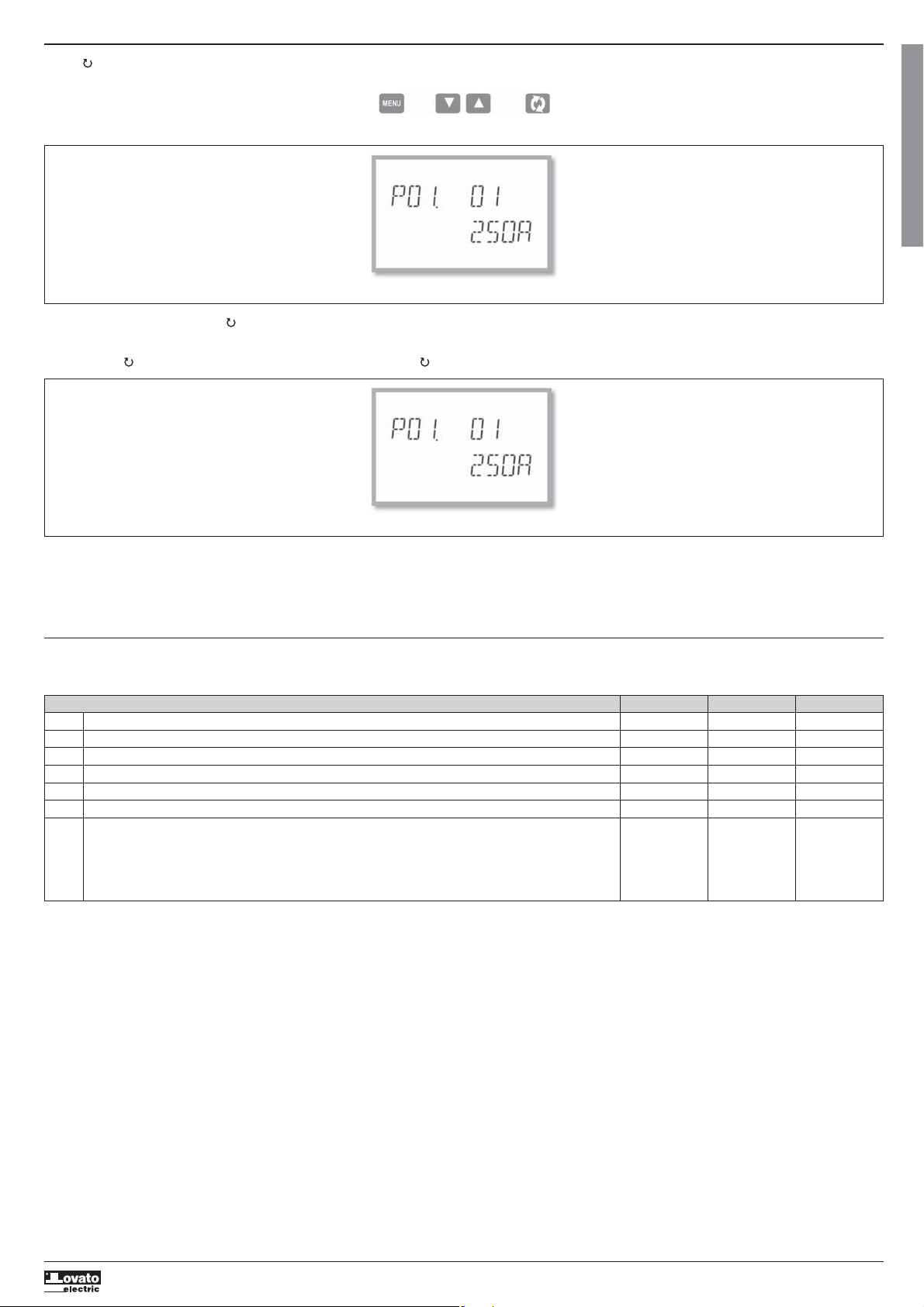
– Press to access the selected menu.
– At this point the sub-menu (if applicable) and sequential parameter number can be selected, again using the buttons as follows:
Back Increase/decrease Next
I422 GB I 10 17 31100212
Set-up: selecting the parameter number
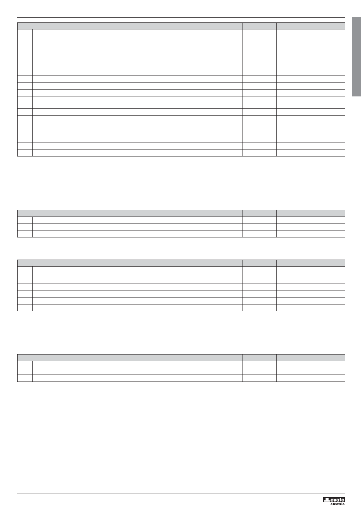
– Once the desired parameter number is set, switches to parameter value edit mode, with the parameter shown in the alphanumeric display.
– Pressing
– Pressing
– Pressing
– Pressing MENU stores the parameter and returns to the previous level, i.e. parameter selection.
– Press MENU several times to exit and save the parameters. The device will reboot.
– Alternatively, from within programming, holding down MENU continuously for three seconds saves changes and exits directly.
– If no buttons are pressed for two minutes, the set-up menu is abandoned automatically and the system returns to the standard display without saving the parameters.
– Remember that, solely for the data that can be edited using the buttons, a backup copy can be made in the DMG100-110’s EEPROM. If required, this data can be restored to the working memory. The backup and
or changes the parameter within the permitted range.
and simultaneously restores the factory default value.
and simultaneously sets the minimum possible value, while pressing and sets the maximum.
date restore commands are in the commands menu.
Setting the parameter value
G
B
PARAMETER TABLE
– All available programming parameters are indicated in the following table. For each parameter the range of possible settings and factory default are shown, in addition to an explanation of the parameter’s function.
The description of the parameter visible on the display may in some cases vary from that indicated in the table due to the limited number of characters available. The parameter code is a valid reference in any case.
M01 - GENERAL UdM Default Range
P01.01 CT primary A 5 1-10000
P01.02 CT secondary A 5 1-5
P01.03 Rated voltage V 400 50-500000
P01.04 Use VT OFF OFF-ON
P01.05 VT primary V 100 50-500000
P01.06 VT secondary V 100 50-500
P01.07 Wiring configuration L1-L2-L3-N L1-L2-L3-N
L1-L2-L3
L1-L2-L3-N BIL
L1-L2-L3 BIL
L1-N-L2
L1-N
P01.01 – Rated current of CT primary winding.
P01.02 – Current of CT secondary winding.
P01.03 – Rated voltage of system.
P01.04 – Program as ON if VTs are used. If programmed as OFF, the next two parameters are ignored.
P01.05 – Rated voltage of VT primary winding.
P01.06 – Rated voltage of VT secondary winding.
P01.07 – Set in accordance with the connection scheme adopted. See Connection Schemes at the end of the manual.
7
Page 8
M02 - UTILITY UdM Default Range
P02.01 Language English English
Italiano
Francais
Espanol
Portuguese
Deutsch
P02.02 High backlight level % 100 0-100
P02.03 Low backlight level % 30 0-50
P02.04 Low backlight delay s 30 5-600
P02.05 Default page return s 60 OFF / 10-600
P02.06 Default page VL-L VL-L / VL-N …
I422 GB I 10 17 31100212
P02.07 Default sub-page INST INST / HI / LO /
AVG / MD
P02.08 Display update time s 0.5 0.1 – 5.0
P02.09 Exported energy measure OFF OFF-ON
P02.10 Phase energy measure OFF OFF-ON
P02.11 Asymmetry measure OFF OFF-ON
P02.12 THD/harmonic measure OFF OFF-THD-THD/HAR
P02.13 Power unbalance measurement OFF OFF-ON
P02.14 Backlight flash when in alarm OFF OFF-ON
P02.05 – If set to OFF, the display always remains on the page where the user left it. If set to a value, after this time the display returns to the page set with P02.06.
P02.06 – Number of the page that the display returns to automatically once the time P02.05 since a button was last pressed has elapsed.
P02.07 – Type of sub-page that the display returns to after P02.05 has elapsed.
P02.09 – Enables the measurement and display of exported energies (generated in the mains).
P02.10 – Enables the measurement and display of energies by individual phase.
P02.11 – Enables the measurement and display of voltage and current asymmetry.
P02.12 – Enables the measurement and display of voltage and current THDs (% Harmonic Distortion).
P02.13 – Enables the calculation and display of phase power unbalance.
P02.14 – When there is an alarm, the display’s backlight flashes to highlight the fault.
M03 - PASSWORD UdM Default Range
P03.01 Enable passwords OFF OFF-ON
P03.02 User level password 1000 0-9999
P03.03 Advanced level password 2000 0-9999
P03.01 – If set to OFF, password management is disabled and there is free access to settings and the commands menu.
P03.02 – With P03.01 active, value to specify to activate user-level access. See Password Access section.
P03.03 – As P03.02, with reference to advanced-level access.
M04 - INTEGRATION UdM Default Range
P04.01 Integration mode Shift Fixed
Shift
Bus (DMG110)
P04.02 Power integration time min 15 1-60
P04.03 Current integration time min 15 1-60
P04.04 Voltage integration time min 1 1-60
P04.05 Frequency integration time min 1 1-60
P04.01 – Integrated measurement calculation mode selection.
Fixed = The instantaneous measurements are integrated for the time set. Each time that the time set elapses, the integrated measurement is updated with the result of the latest integration.
Shift = he instantaneous measurements are integrated for a time = 1/15 of the time set. Each time this interval elapses, the oldest value is replaced with the new value calculated. The integrated
measurement is updated every 1/15 of the time set, considering a time-shift window that includes the last 15 values calculated, equivalent in length to the time set.
Bus = As fixed mode, but the integration intervals are dictated by synchronisation messages sent on the serial bus. (110)
P04.02 – Average (AVG) measurement integration time for active, reactive and apparent power.
P04.03, P04.04, P04.05 – Average (AVG) measurement integration time for the corresponding values.
M05 - HOUR COUNTER UdM Default Range
P05.01 Hour counters general enable ON OFF-ON
P05.02 Partial hour counter enable ON OFF-ON-LIMx
P05.03 Channel number (x) 1 1-4
P05.01 – If Off, the hour counters are disabled and the hour counter measurement page is not displayed.
P05.02 – If OFF, the partial hour counter is not incremented. If ON, it is incremented when the multimeter is supplied. If linked to one of the internal variables (LIMn), it is incremented only when this condition is true.
P05.03 – Channel number (x) of any internal variable used in the previous parameter. Example: If the partial hour counter needs to count the time that a measurement is above a certain threshold, defined by LIM3,
program LIMx in the previous parameter and specify 3 in this parameter.
G
B
8
Page 9
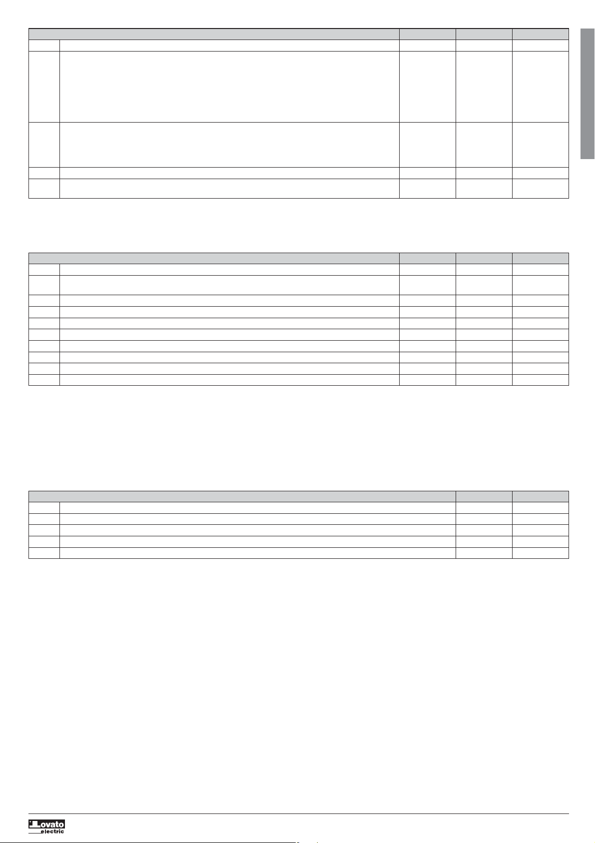
M07 - COMMUNICATION (DMG110 only) UdM Default Range
P07.01 Serial node address 01 01-255
P07.02 Serial speed bps 9600 1200
2400
4800
9600
19200
38400
57600
115200
P07.03 Data format 8 bit – n 8 bit, no parity
8 bit, odd
8bit, even
7 bit, odd
I422 GB I 10 17 31100212
7 bit, even
P07.04 Stop bits 1 1-2
P07.05 Protocol Modbus RTU Modbus RTU
Modbus ASCII
P07.n.01 – Serial address (node) for the communication protocol.
P07.n.02 – Communication port bitrate.
P07.n.03 – Data format. 7-bit settings available for ASCII protocol only.
P07.n.04 – Number of stop bits.
P07.n.05 – Communication protocol selection.
M08 - LIMIT THRESHOLDS (LIMn, n=1..4) UdM Default Range
P08.n.01 Reference measure OFF OFF- (measures)
P08.n.02 Function Max Max – Min –
Min+Max
P08.n.03 Upper threshold 0 -9999 - +9999
P08.n.04 Multiplier x1 /100 – x10k
P08.n.05 Delay s 0 0.0 – 1000.0
P08.n.06 Lower threshold 0 -9999 - +9999
P08.n.07 Multiplier x1 /100 – x10k
P08.n.08 Delay s 0 0.0 – 1000.0
P08.n.09 Normal status OFF OFF-ON
P08.n.10 Latch OFF OFF-ON
Note: this menu is divided into 4 sections, for limit thresholds LIM1..4
P08.n.01 – Defines which multimeter measurement the limit threshold is applied to.
P08.n.02 – Defines the function of the limit threshold. It can be:
P08.n.03 and P08.n.04 – Define the upper threshold, which results from multiplying value P08.n.03 by P08.n.04.
P08.n.05 – Trip delay on upper threshold.
P08.n.06, P08.n.07, P08.n.08 – as above, with reference to the lower threshold.
P08.n.09 – Permits inversion of the status of limit threshold LIMn.
P08.n.10 – Defines whether the threshold is stored and must be reset manually (ON) or is reset automatically (OFF).
Max = LIMn active when measurement exceeds P08.n.03. P08.n.06 is the reset threshold.
Min = LIMn active when measurement is below P08.n.06. P08.n.03 is the reset threshold.
Min+Max = LIMn active when measurement is above P08.n.03 or below P08.n.06.
G
B
M09 - ALARMS (ALAn, n=1..4) Default Range
P09.n.01 Alarm source OFF OFF-LIMx
P09.n.02 Channel number (x) 1 1-4
P09.n.03 Latch OFF OFF-ON
P09.n.04 Priority Low Low - High
P09.n.05 Text ALAn (text: 16 characters
Note: this menu is divided into 4 sections, for alarms ALA1..4
P09.n.01 – Signal that causes the alarm. It can be when a threshold (LIMx) is exceeded.
P09.n.02 – Channel number (x), with reference to the previous parameter.
P09.n.03 – Defines whether the alarm is stored and must be reset manually (ON) or is reset automatically (OFF).
P09.n.04 – If the alarm has a priority of high, its activation switches the display to the alarm page automatically and it is displayed with the alarm icon. If instead it is set to low priority, the page does not change and
P09.n.05 – Free text for alarm. 16 characters max.
it is displayed with the ‘information’ icon.
9
Page 10
COMMANDS MENU
– The commands menu permits the execution of occasional operations such as resetting measurements, meters, counter, etc.
– If the advanced-access password has been entered, the commands menu can also be used to perform some automatic operations that are useful for configuring the instrument.
– The following table indicates the functions available through the commands menu, divided by required access level.
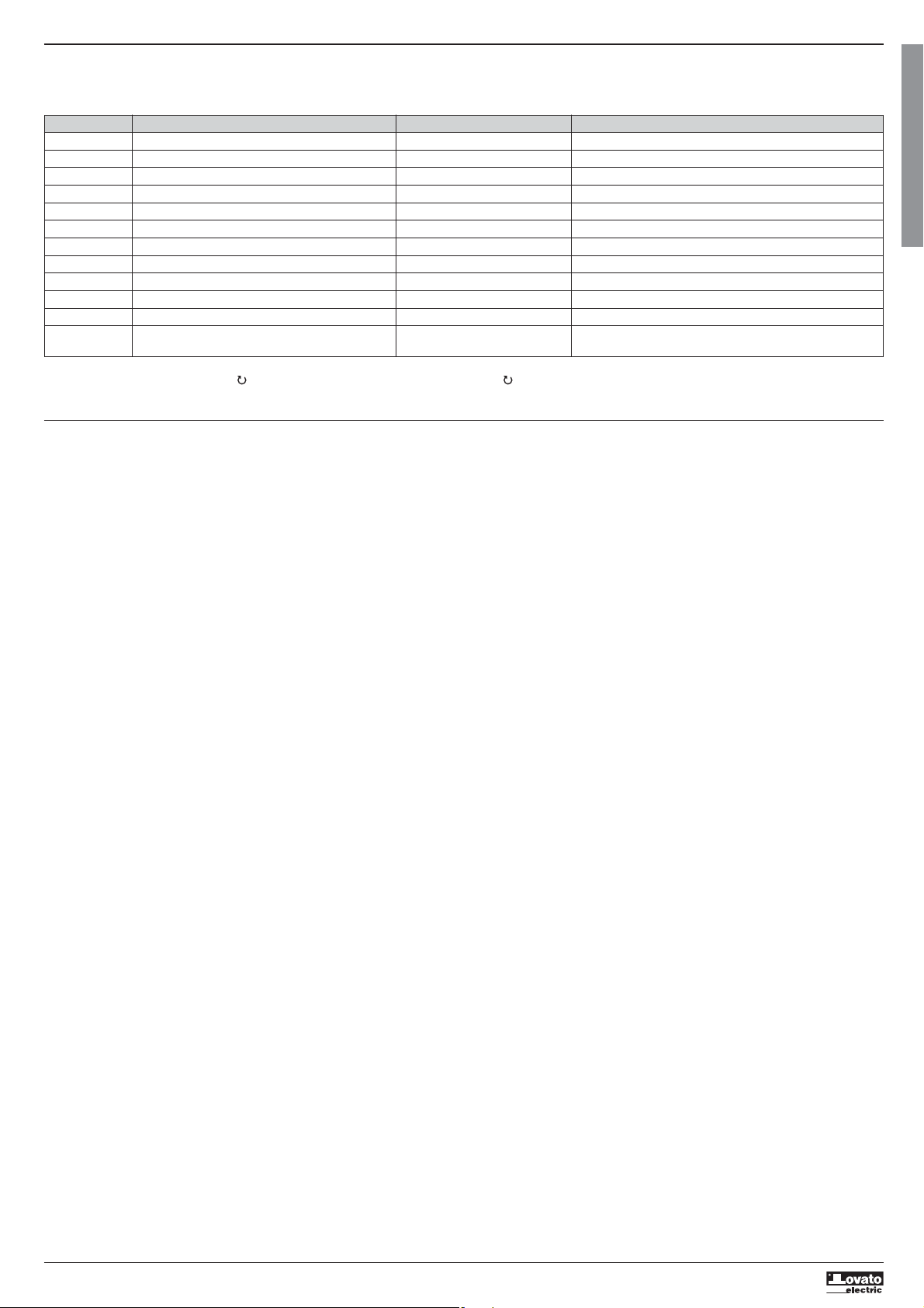
Code COMMAND ACCESS LEVEL DESCRIPTION
C.01 RESET HI-LO User / Advanced Resets the HI and LO values of all measurements
C.02 RESET MAX DEMAND User / Advanced Resets Max Demand values for all measurements
C.03 RESET PARTIAL ENERGY METERS User / Advanced Resets partial energy meters
C.04 RESET PARTIAL HOUR COUNTER User / Advanced Resets partial hour counters
C.07 RESET ALARMS User / Advanced Resets alarms with latch
C.08 RESET LIMITS User / Advanced Resets limit thresholds with latch
C.11 RESET TOTAL ENERGY METER Advanced Resets total and partial energy meters
I422 GB I 10 17 31100212
C.12 RESET TOTAL HOUR COUNTERS Advanced Resets total hour counters
C.13 PARAMETERS TO DEFAULT Advanced Restores all settings to factory default values
C.14 PARAMETER BACKUP Advanced Saves a backup copy of the settings
C.15 PARAMETERS RESTORE Advanced Reloads the settings from the backup copy
C.16 WIRING TEST Advanced Runs the test to check that the DMG is connected correctly.
– Once the desired command is selected, press to execute it. The instrument will request confirmation. Pressing again will execute the command.
– To cancel the execution of a selected command, press MENU.
– To abandon the command menu, press MENU.
CONNECTION TEST
– The connection test permits verification of the correct installation of the multimeter.
– In order to run the test, the multimeter must be connected to an active system with the following conditions:
• three-phase system with all phases present (V > 50VAC PH-N)
• minimum current flow in each phase > 1% of the CT full scale set
• positive flow of energies (i.e. a normal system where the inductive load draws power from the supply)
– To launch the test, enter the commands menu and select command C.16, according to the instructions in the Commands Menu section.
– The test permits verification of the following:
• reading of the three voltages
• phase sequence
• voltage unbalance
• reverse polarity of one or more CTs
• mismatch between voltage/current phases
– If the test is not passed, the display shows the reason for the failure.
See Connection Test section
G
B
10
Page 11
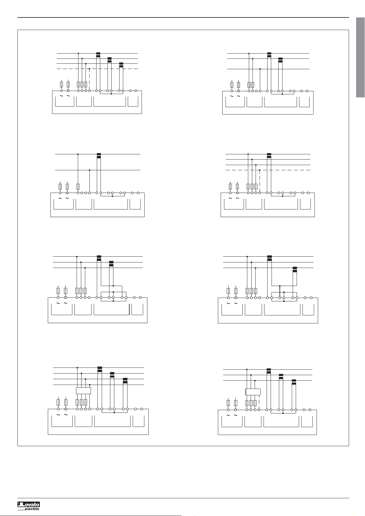
CONNECTION SCHEMES
I422 GB I 10 17 31100212
3-phase connection whit or without neutral
P01.07 = L1-L2-L3-N L1-L2-L3
V1 VNV2 V3
VOLTAGE
TA/CT1
S1
S2
I1
TA/CT2
S2S1
CURRENT
S2S1
S1 S2 S1 S2
L1
L2
L3
N
100...240VAC
110...250VDC
---
A1
AUX SUPPLY
+
A2
Single-phase connection
P01.07 = L1-N
V1 VNV2 V3
VOLTAGE
TA/CT1
S1
I1
S2
S2S1
S1 S2 S1 S2
CURRENT
L1
N
100...240VAC
110...250VDC
---
A1
AUX SUPPLY
+
A2
2-phase connection
P01.07 = L1-N-L2
V1 VNV2 V3
VOLTAGE
TA/CT1
S1
I1
S2
S2S1
TA/CT2
S2S1
S1 S2 S1 S2
CURRENT
L
O
A
D
AB
I3I2
RS485
G
B
TA/CT3
L
O
A
S2S1
I3I2
D
A B
RS485
L1
L2
N
100...240VAC
110...250VDC
---
A1
AUX SUPPLY
+
A2
Balanced 3-phase connection whit or without neutral
P01.07 = L1-L2-L3-N-BIL L1-L2-L3-BIL
V1 VNV2 V3
VOLTAGE
TA/CT1
S2
S1
I1
S2S1
CURRENT
S1 S2 S1 S2
I2
L
O
A
D
A B
I3
RS485
L
O
A
D
AB
I3
I2
RS485
L1
L2
L3
N
100...240VAC
110...250VDC
---
A1
AUX SUPPLY
+
A2
ARON connection 3-phase without neutral
P01.07 = L1-L2-L3
V1 VNV2 V3
VOLTAGE
TA/CT1
S1
I1
S2
S2S1
L1
L2
L3
100...240VAC
110...250VDC
A1
AUX SUPPLY
+
---
A2
3 phase connection with neutral via VT
Set P01.04, P01.05 and P01.06
P01.07 = L1-L2-L3-N
TV/VT
VOLTAGE
TA/CT1
S1
S2
S2S1
I1
L1
L2
L3
N
100...240VAC
110...250VDC
A1
AUX SUPPLY
V1 VNV2 V3
+
---
A2
TA/CT2
S2S1
S1 S2 S1 S2
CURRENT
TA/CT2
S2S1
S1 S2 S1 S2
I2
CURRENT
I3I2
TA/CT3
ARON connection 3-phase without neutral
P01.07 = L1-L2-L3
VOLTAGE
TA/CT1
S1
I1
S2
S2S1
S1 S2 S1 S2
CURRENT
TA/CT3
L
O
A
S2S1
I3I2
D
A B
RS485
A B
RS485
L
O
A
D
L1
L2
L3
N
100...240VAC
110...250VDC
---
A1
AUX SUPPLY
V1 VNV2 V3
+
A2
3 phase connection without neutral via VT
Set P01.04, P01.05 and P01.06
P01.07 = L1-L2-L3
TV/VT
V1 VNV2 V3
VOLTAGE
TA/CT1
S1
I1
S2
S2S1
TA/CT2
S2S1
S1 S2 S1 S2
CURRENT
TA/CT3
I3I2
L
O
A
S2S1
D
A B
RS485
L
O
A
S2S1
I3
D
A B
RS485
L1
L2
L3
100...240VAC
110...250VDC
---
A1
AUX SUPPLY
+
A2
NOTES
1. Recommended fuses:
aux supply and measure inputs voltage: F1A (fast).
2. S2 terminals are internally interconnected.
3. Class 1 CTs should be used. In case of DMG110 and VLN>300V, class 2 CTs must be installed.
11
Page 12
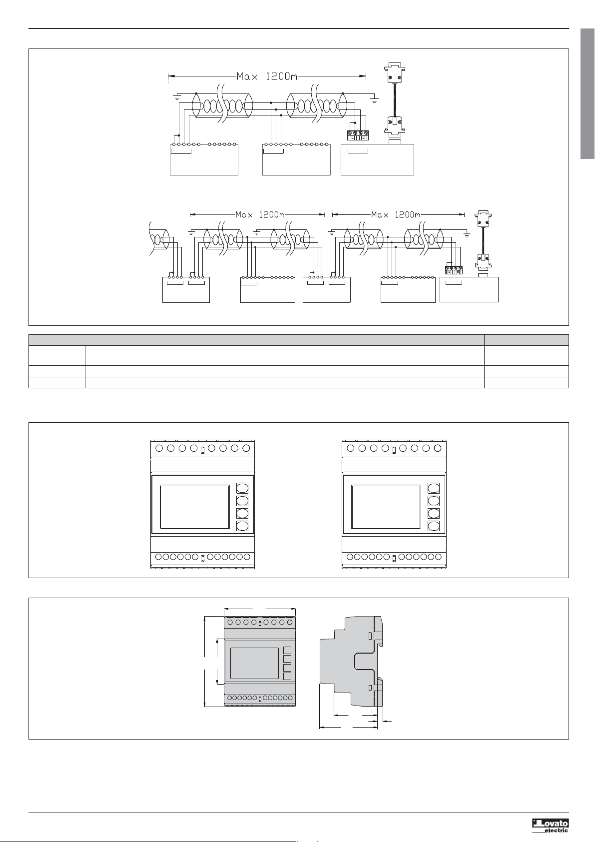
PC-DMG110 CONNECTION VIA RS485 INTERFACE
PC
Cable
51C4
G
B
SGBTR A
Interface converter
RS232/485
PX1
I422 GB I 10 17 31100212
SG
ABTR
RS485
DMG110 n°31
TR SGAB
RS485
DMG110 n°1
PC
Cable
51C4
Repeat this wiring diagram
up to 255 devices
TR
TR SGAB SGAB
Interface
converter
RS232/485
PX1
TR ABSG
RS485
DMG110
Device addresses n° 31-60
BTR A SG BTR A SG
Interface
converter
RS232/485
PX1
Set as repeaterSet as repeater
TRSGSGBA
RS485
DMG110
Device addresses n° 1-30
TR A B
Interface converter
RS232/485
PX1
Remote control
Order Description Weight (kg)
codes
4PX1 RS232/RS-485 galvanically isolated converter drive 220…240 Vac supply. 0.600
51C4 PC- RS232/RS-485 converter drive connection cable, length 1.80 metres. 0.147
RS232/RS-485 galvanically isolated bench converter drive, 38,400 Baud-rate max., automatic or manual TRANSMIT line supervision, 220…240 Vac ±10% supply (or 110…120 Vac on request).
TERMINAL LAYOUT
DMG100 DMG110
A1 A2 V2V1 V3 VN
MECHANICAL DIMENSIONS AND PANEL CUT-OUT (mm)
S1
90
I1 I2
S2
45
S1 S1
S2
A1 A2
I3
S2
TR
SGBA
I1 I2
S1
V2V1 V3 VN
S1 S1
S2
I3
S2
S2
72
43.7
58
5
12
Page 13
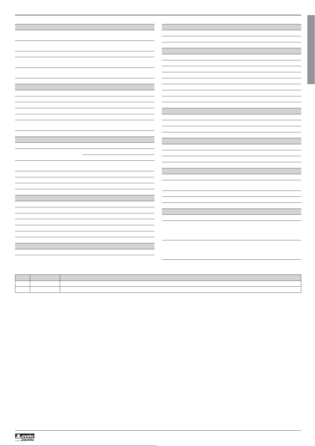
TECHNICAL CHARACTERISTICS
Supply
or 5 A
) ±0.5 digit
) ±0.5 digit
Rated voltage Us 100 - 240V
110 - 250V=
Operating voltage range 90 - 264V
93.5 - 300V=
Frequency 45 - 66Hz
Power consumption/dissipation DMG100 0.5W – 1.5VA
Immunity time for microbreakings DMG100 >= 40ms
Recommended fuses F1A (fast)
I422 GB I 10 17 31100212
Voltage input
Max. rated voltage Ue 600 VAC L-L (346 VAC L-N)
Measuring range 90…720 V L-L (50...415 VAC L-N)
Frequency range 45…65 Hz
Measurement type True root mean square (TRMS)
Measurement input impedance L-N - L-L > 8MΩ
Connection method Single-phase, two-phase, three-phase with or
without neutral or balanced three-phase system
Recommended fuses F1A (fast)
Current inputs
Rated current Ie 1 A
Measuring range For 5 A scale: 0.025 - 6 A
For 1 A scale: 0.025 – 1.2 A
Input type Shunt supplied by an external current transformer
(low voltage). 5 A max.
Measurement type Root mean square (RMS)
Overload capacity +20% Ie
Overload peak 50 A for 1 second
Burden (per phase) ≤0.6 VA
Measurement accuracy
Measuring conditions
Temperature +23 °C ±2 °C
Voltage (phase to neutral) ± 0.5% (50…415 V
Voltage (phase to phase) ± 0.5% (90…720 V
Current (CT /5) ± 0.5% (0.1…1.2In) ±0.5 digit
Active energy Class 1 (IEC/EN 62053-21)
Reactive energy Class 2 (IEC/EN 62053-23)
Additional errors
Temperature 0.05%/°K per V, A, W
MANUAL REVISION HISTORY
REV. DATE NOTES
00 26/01/2015 First release
01 19/03/2015 Change of range for P08.n.05 and P08.n.08
DMG110 0.8W – 2.2VA
DMG110 >= 30ms
Insulation
Rated insulation voltage Ui 600 V
Rated impulse withstand voltage Uimp 9.5 kV
Power frequency withstand voltage 5.2 kV
Ambient conditions
Operating temperature -20 - +60°C
Storage temperature -30 - +80°C
Relative humidity <80% (IEC/EN 60068-2-78)
Maximum pollution degree 2
Overvoltage category 3
Measurement category III
Climatic sequence Z/ABDM (IEC/EN 60068-2-61)
Shock resistance 15g (IEC/EN 60068-2-27)
Vibration resistance 0.7g (IEC/EN 60068-2-6)
Auxiliary supply and voltage input connections
Type of terminal Screw (fixed)
Number of terminals 4 for voltage inputs / 2 for Aux supply
Conductor cross section (min… max) 0.2 - 4.0 mm
Tightening torque 0.8Nm (7lbin)
Current Input and RS485 (DMG110 only) connections
Terminal type Screw (fixed)
Number of terminals 6 for CT connection / 4 for RS485 connection
Conductor cross section (min… max) 0.2 – 2.5 mmq (24 - 12 AWG)
Tightening torque 0.44 Nm (4 lbin)
Housing
Version 4 modules (DIN 43880)
Mounting 35mm DIN rail (EN60715) or by screw using
extractible clips
Material Polyamide RAL7035
Degree of protection IP40 on front / IP20 terminals
Weight 300g
Certifications and compliance
Certifications obtained cULus, RCM, EAC
Comply with standards IEC/EN 61010-1, IEC/EN 61010-2-030,
IEC/EN 61000-6-2, IEC/ EN 61000-6-3,
UL 61010-1, CSA C22.2 n° 61010-1,
UL 61010-2-030, CSA 22.2 n° 61010-2-030
UL Marking Use 75°C min copper (CU) conductor only
AWG Range: 18 - 12 AWG stranded or solid
Field Wiring Terminals Tightening Torque: 4.5lb.in
Flat panel mounting on a Type 1 enclosure
Auxiliary supply from a system with a phase-neutral voltage ≤300V
2
(24 - 12 AWG)
G
B
13
Page 14
LOVATO ELECTRIC S.P.A.
24020 GORLE (BERGAMO) ITALIA
VIA DON E. MAZZA, 12
TEL. 035 4282111
FAX (Nazionale): 035 4282200
FAX (International): +39 035 4282400
E-mail info@
Web www.
I422 GB I 10 17 31100212
L
ovatoElectric.com
L
ovatoElectric.com
MULTIMETRO DIGITALE
I
Manuale operativo
DMG100 – DMG110
WARNING!
– Carefully read the manual before the installation or use.
– This equipment is to be installed by qualified personnel, complying to current standards, to avoid
damages or safety hazards.
– Before any maintenance operation on the device, remove all the voltages from measuring and supply inputs and short-
circuit the CT input terminals.
– The manufacturer cannot be held responsible for electrical safety in case of improper use of the equipment.
– Products illustrated herein are subject to alteration and changes without prior notice. Technical data and descriptions
in the documentation are accurate, to the best of our knowledge, but no liabilities for errors, omissions or
contingencies arising there from are accepted.
– A circuit breaker must be included in the electrical installation of the building. It must be installed close by the
equipment and within easy reach of the operator. It must be marked as the disconnecting device of the equipment:
IEC /EN 61010-1 § 6.11.2.
– Clean the instrument with a soft dry cloth; do not use abrasives, liquid detergents or solvents.
ATTENTION !
– Lire attentivement le manuel avant toute utilisation et installation.
– Ces appareils doivent être installés par un personnel qualifié, conformément aux normes en vigueur en
matière d'installations, afin d'éviter de causer des dommages à des personnes ou choses.
– Avant toute intervention sur l'instrument, mettre les entrées de mesure et d'alimentation hors tension et court-circuiter
les transformateurs de courant.
– Le constructeur n'assume aucune responsabilité quant à la sécurité électrique en cas d'utilisation impropre du
dispositif.
– Les produits décrits dans ce document sont susceptibles d'évoluer ou de subir des modifications à n'importe quel
moment. Les descriptions et caractéristiques techniques du catalogue ne peuvent donc avoir aucune valeur
contractuelle.
– Un interrupteur ou disjoncteur doit être inclus dans l'installation électrique du bâtiment. Celui-ci doit se trouver tout
près de l'appareil et l'opérateur doit pouvoir y accéder facilement. Il doit être marqué comme le dispositif
d'interruption de l'appareil : IEC/ EN 61010-1 § 6.11.2.
– Nettoyer l'instrument avec un chiffon doux, ne pas utiliser de produits abrasifs, détergents liquides ou solvants.
ACHTUNG!
– Dieses Handbuch vor Gebrauch und Installation aufmerksam lesen.
– Zur Vermeidung von Personen- und Sachschäden dürfen diese Geräte nur von qualifiziertem
Fachpersonal und unter Befolgung der einschlägigen Vorschriften installiert werden.
– Vor jedem Eingriff am Instrument die Spannungszufuhr zu den Messeingängen trennen und die Stromwandler
kurzschlieβen.
– Bei zweckwidrigem Gebrauch der Vorrichtung übernimmt der Hersteller keine Haftung für die elektrische Sicherheit.
– Die in dieser Broschüre beschriebenen Produkte können jederzeit weiterentwickelt und geändert werden. Die im
Katalog enthaltenen Beschreibungen und Daten sind daher unverbindlich und ohne Gewähr.
– In die elektrische Anlage des Gebäudes ist ein Ausschalter oder Trennschalter einzubauen. Dieser muss sich in
unmittelbarer Nähe des Geräts befinden und vom Bediener leicht zugänglich sein. Er muss als Trennvorrichtung für das
Gerät gekennzeichnet sein: IEC/ EN 61010-1 § 6.11.2.
– Das Instrument mit einem weichen Tuch reinigen, keine Scheuermittel, Flüssigreiniger oder Lösungsmittel verwenden.
ATTENZIONE!
– Leggere attentamente il manuale prima dell’utilizzo e l’installazione.
– Questi apparecchi devono essere installati da personale qualificato, nel rispetto delle vigenti normative
– Prima di qualsiasi intervento sullo strumento, togliere tensione dagli ingressi di misura e di alimentazione e
– Il costruttore non si assume responsabilità in merito alla sicurezza elettrica in caso di utilizzo improprio del dispositivo.
– I prodotti descritti in questo documento sono suscettibili in qualsiasi momento di evoluzioni o di modifiche. Le
– Un interruttore o disgiuntore va compreso nell’impianto elettrico dell’edificio. Esso deve trovarsi in stretta vicinanza
– Pulire lo strumento con panno morbido, non usare prodotti abrasivi, detergenti liquidi o solventi.
UWAGA!
– Przed użyciem i instalacją urządzenia należy uważnie przeczytać niniejszą instrukcję.
– W celu uniknięcia obrażeń osób lub uszkodzenia mienia tego typu urządzenia muszą być instalowane przez
– Przed rozpoczęciem jakichkolwiek prac na urządzeniu należy odłączyć napięcie od wejść pomiarowych i zasilania oraz zewrzeć
– Producent nie przyjmuje na siebie odpowiedzialności za bezpieczeństwo elektryczne w przypadku niewłaściwego użytkowania
– Produkty opisane w niniejszym dokumencie mogą być w każdej chwili udoskonalone lub zmodyfikowane. Opisy oraz dane
– W instalacji elektrycznej budynku należy uwzględnić przełącznik lub wyłącznik automatyczny. Powinien on znajdować się w
– Urządzenie należy czyścić miękką szmatką, nie stosować środkow ściernych, płynnych detergentow lub rozpuszczalnikow.
•
•
•
•
•
•
•
impiantistiche, allo scopo di evitare danni a persone o cose.
cortocircuitare i trasformatori di corrente.
descrizioni ed i dati a catalogo non possono pertanto avere alcun valore contrattuale.
dell’apparecchio ed essere facilmente raggiungibile da parte dell’operatore. Deve essere marchiato come il dispositivo
di interruzione dell’apparecchio: IEC/ EN 61010-1 § 6.11.2.
wykwalifikowany personel, zgodnie z obowiązującymi przepisami.
zaciski przekładnika prądowego.
urządzenia.
katalogowe nie mogą mieć w związku z tym żadnej wartości umownej.
bliskim sąsiedztwie urządzenia i być łatwo osiągalny przez operatora. Musi być oznaczony jako urządzenie służące do
wyłączania urządzenia: IEC/ EN 61010-1 § 6.11.2.
警告
安装或使用前︐
本
建筑物
的
断开所
︐
︒
︐以避免造
有
IEC /EN 61010-1 § 6.11.2
成
端子的
︒
CT
︐并短
接
︒
I
ADVERTENCIA
– Leer atentamente el manual antes de instalar y utilizar el regulador.
– Este dispositivo debe ser instalado por personal cualificado conforme a la normativa de instalación
vigente a fin de evitar daños personales o materiales.
– Antes de realizar cualquier operación en el dispositivo, desconectar la corriente de las entradas de alimentación y
medida, y cortocircuitar los transformadores de corriente.
– El fabricante no se responsabilizará de la seguridad eléctrica en caso de que el dispositivo no se utilice de forma
adecuada.
– Los productos descritos en este documento se pueden actualizar o modificar en cualquier momento. Por consiguiente,
las descripciones y los datos técnicos aquí contenidos no tienen valor contractual.
– La instalación eléctrica del edificio debe disponer de un interruptor o disyuntor. Éste debe encontrarse cerca del
dispositivo, en un lugar al que el usuario pueda acceder con facilidad. Además, debe llevar el mismo marcado que el
interruptor del dispositivo (IEC/ EN 61010-1 § 6.11.2).
– Limpiar el dispositivo con un trapo suave; no utilizar productos abrasivos, detergentes líquidos ni disolventes.
UPOZORNĚNÍ
– Návod se pozorně pročtěte, než začnete regulátor instalovat a používat.
– Tato zařízení smí instalovat kvalifikovaní pracovníci v souladu s platnými předpisy a normami pro předcházení
úrazů osob či poškození věcí.
– Před jakýmkoli zásahem do přístroje odpojte měřicí a napájecí vstupy od napětí a zkratujte transformátory proudu.
– Výrobce nenese odpovědnost za elektrickou bezpečnost v případě nevhodného používání regulátoru.
– Výrobky popsané v tomto dokumentu mohou kdykoli projít úpravami či dalším vývojem. Popisy a údaje uvedené v katalogu
nemají proto žádnou smluvní hodnotu.
– Spínač či odpojovač je nutno zabudovat do elektrického rozvodu v budově. Musejí být nainstalované v těsné blízkosti přístroje a
snadno dostupné pracovníku obsluhy. Je nutno ho označit jako vypínací zařízení přístroje: IEC/ EN 61010-1 § 6.11.2.
– Přístroj čistěte měkkou utěrkou, nepoužívejte abrazivní produkty, tekutá čistidla či rozpouštědla.
AVERTIZARE!
– Citiţi cu atenţie manualul înainte de instalare sau utilizare.
– Acest echipament va fi instalat de personal calificat, în conformitate cu standardele actuale, pentru a evita
deteriorări sau pericolele.
– Înainte de efectuarea oricărei operaţiuni de întreţinere asupra dispozitivului, îndepărtaţi toate tensiunile de la intrările de
măsurare şi de alimentare şi scurtcircuitaţi bornele de intrare CT.
– Produsele ilustrate în prezentul sunt supuse modificărilor şi schimbărilor fără notificare anterioară.
– Datele tehnice şi descrierile din documentaţie sunt precise, în măsura cunoştinţelor noastre, dar nu se acceptă nicio răspundere
pentru erorile, omiterile sau evenimentele neprevăzute care apar ca urmare a acestora.
– Trebuie inclus un disjunctor în instalaţia electrică a clădirii. Acesta trebuie instalat aproape de echipament şi într-o zonă uşor
accesibilă operatorului. Acesta trebuie marcat ca fiind dispozitivul de deconectare al echipamentului: IEC/EN 61010-1 § 6.11.2.
– Curăţaţi instrumentul cu un material textil moale şi uscat; nu utilizaţi substanţe abrazive, detergenţi lichizi sau solvenţi.
ПРЕДУПРЕЖДЕНИЕ!
– Прежде чем приступать к монтажу или эксплуатации устройства, внимательно ознакомьтесь с одержанием
– Во избежание травм или материального ущерба монтаж должен существляться только квалифицированным персоналом
– Перед проведением любых работ по техническому обслуживанию устройства необходимо обесточить все
– Производитель не несет ответственность за обеспечение электробезопасности в случае ненадлежащего использования
– Изделия, описанные в настоящем документе, в любой момент могут подвергнуться изменениям или
– Электрическая сеть здания должна быть оснащена автоматическим выключателем, который должен быть расположен
– Очистку устройства производить с помощью мягкой сухой ткани, без применения абразивных материалов, жидких
DİKKAT!
– Montaj ve kullanımdan önce bu el kitabını dikkatlice okuyunuz.
– Bu aparatlar kişilere veya nesnelere zarar verme ihtimaline karşı yürürlükte olan sistem kurma normlarına göre
– Aparata (cihaz) herhangi bir müdahalede bulunmadan önce ölçüm girişlerindeki gerilimi kesip akım transformatörlerinede kısa
– Üretici aparatın hatalı kullanımından kaynaklanan elektriksel güvenliğe ait sorumluluk kabul etmez.
– Bu dokümanda tarif edilen ürünler her an evrimlere veya değişimlere açıktır. Bu sebeple katalogdaki tarif ve değerler herhangi bir
– Binanın elektrik sisteminde bir anahtar veya şalter bulunmalıdır. Bu anahtar veya şalter operatörün kolaylıkla ulaşabileceği yakın
– Aparatı (cihaz) sıvı deterjan veya solvent kullanarak yumuşak bir bez ile siliniz aşındırıcı temizlik ürünleri kullanmayınız.
настоящего руководства.
в соответствии с действующими нормативами.
измерительные и питающие входные контакты, а также замкнуть накоротко входные контакты трансформатора тока (ТТ).
устройства.
усовершенствованиям. Поэтому каталожные данные и описания не могут рассматриваться как действительные с точки
зрения контрактов
вблизи оборудования в пределах доступа оператора. Автоматический выключатель должен быть промаркирован как
отключающее устройство оборудования: IEC /EN 61010-1 § 6.11.2.
моющих средств или растворителей.
kalifiye personel tarafından monte edilmelidirler
devre yaptırınız.
bağlayıcı değeri haiz değildir.
bir yerde olmalıdır. Aparatı (cihaz) devreden çıkartma görevi yapan bu anahtar veya şalterin markası: IEC/ EN 61010-1 § 6.11.2.
14
Page 15
INDICE Pagina
Introduzione. . . . . . . . . . . . . . . . . . . . . . . . . . . . . . . . . . . . . . . . . . . . . . . . . . . . . . . . . . . . . . . . . . . . . . . . . . . . . . . . . . . . . . . . . . . . . . . . . . . . . . . . . . . . . . . . . . . . . . . . . . . . . . . . . . . . . . . . . . . . . . . . . . . . . . . . . . . . . 15
Descrizione . . . . . . . . . . . . . . . . . . . . . . . . . . . . . . . . . . . . . . . . . . . . . . . . . . . . . . . . . . . . . . . . . . . . . . . . . . . . . . . . . . . . . . . . . . . . . . . . . . . . . . . . . . . . . . . . . . . . . . . . . . . . . . . . . . . . . . . . . . . . . . . . . . . . . . . . . . . . . 15
Funzione dei tasti frontali . . . . . . . . . . . . . . . . . . . . . . . . . . . . . . . . . . . . . . . . . . . . . . . . . . . . . . . . . . . . . . . . . . . . . . . . . . . . . . . . . . . . . . . . . . . . . . . . . . . . . . . . . . . . . . . . . . . . . . . . . . . . . . . . . . . . . . . . . . . . . . . . . . . 15
Indicazioni sul display . . . . . . . . . . . . . . . . . . . . . . . . . . . . . . . . . . . . . . . . . . . . . . . . . . . . . . . . . . . . . . . . . . . . . . . . . . . . . . . . . . . . . . . . . . . . . . . . . . . . . . . . . . . . . . . . . . . . . . . . . . . . . . . . . . . . . . . . . . . . . . . . . . . . . 15
Visualizzazione delle misure . . . . . . . . . . . . . . . . . . . . . . . . . . . . . . . . . . . . . . . . . . . . . . . . . . . . . . . . . . . . . . . . . . . . . . . . . . . . . . . . . . . . . . . . . . . . . . . . . . . . . . . . . . . . . . . . . . . . . . . . . . . . . . . . . . . . . . . . . . . . . . . . 16
Tabella delle pagine del display . . . . . . . . . . . . . . . . . . . . . . . . . . . . . . . . . . . . . . . . . . . . . . . . . . . . . . . . . . . . . . . . . . . . . . . . . . . . . . . . . . . . . . . . . . . . . . . . . . . . . . . . . . . . . . . . . . . . . . . . . . . . . . . . . . . . . . . . . . . . . . 16
Navigazione fra le pagine del display . . . . . . . . . . . . . . . . . . . . . . . . . . . . . . . . . . . . . . . . . . . . . . . . . . . . . . . . . . . . . . . . . . . . . . . . . . . . . . . . . . . . . . . . . . . . . . . . . . . . . . . . . . . . . . . . . . . . . . . . . . . . . . . . . . . . . . . . . . 17
Indicazione contatori energia . . . . . . . . . . . . . . . . . . . . . . . . . . . . . . . . . . . . . . . . . . . . . . . . . . . . . . . . . . . . . . . . . . . . . . . . . . . . . . . . . . . . . . . . . . . . . . . . . . . . . . . . . . . . . . . . . . . . . . . . . . . . . . . . . . . . . . . . . . . . . . . . 18
Indicazione contaore . . . . . . . . . . . . . . . . . . . . . . . . . . . . . . . . . . . . . . . . . . . . . . . . . . . . . . . . . . . . . . . . . . . . . . . . . . . . . . . . . . . . . . . . . . . . . . . . . . . . . . . . . . . . . . . . . . . . . . . . . . . . . . . . . . . . . . . . . . . . . . . . . . . . . . 18
Indicazione analisi armonica . . . . . . . . . . . . . . . . . . . . . . . . . . . . . . . . . . . . . . . . . . . . . . . . . . . . . . . . . . . . . . . . . . . . . . . . . . . . . . . . . . . . . . . . . . . . . . . . . . . . . . . . . . . . . . . . . . . . . . . . . . . . . . . . . . . . . . . . . . . . . . . . 18
Indicazione stato limiti (LIMn) . . . . . . . . . . . . . . . . . . . . . . . . . . . . . . . . . . . . . . . . . . . . . . . . . . . . . . . . . . . . . . . . . . . . . . . . . . . . . . . . . . . . . . . . . . . . . . . . . . . . . . . . . . . . . . . . . . . . . . . . . . . . . . . . . . . . . . . . . . . . . . . 18
Indicazione allarmi . . . . . . . . . . . . . . . . . . . . . . . . . . . . . . . . . . . . . . . . . . . . . . . . . . . . . . . . . . . . . . . . . . . . . . . . . . . . . . . . . . . . . . . . . . . . . . . . . . . . . . . . . . . . . . . . . . . . . . . . . . . . . . . . . . . . . . . . . . . . . . . . . . . . . . . . 19
I422 GB I 10 17 31100212
Menu principale . . . . . . . . . . . . . . . . . . . . . . . . . . . . . . . . . . . . . . . . . . . . . . . . . . . . . . . . . . . . . . . . . . . . . . . . . . . . . . . . . . . . . . . . . . . . . . . . . . . . . . . . . . . . . . . . . . . . . . . . . . . . . . . . . . . . . . . . . . . . . . . . . . . . . . . . . 19
Impostazione parametri (setup) dal pannello frontale . . . . . . . . . . . . . . . . . . . . . . . . . . . . . . . . . . . . . . . . . . . . . . . . . . . . . . . . . . . . . . . . . . . . . . . . . . . . . . . . . . . . . . . . . . . . . . . . . . . . . . . . . . . . . . . . . . . . . . . . . . . . . 19
Tabella dei parametri . . . . . . . . . . . . . . . . . . . . . . . . . . . . . . . . . . . . . . . . . . . . . . . . . . . . . . . . . . . . . . . . . . . . . . . . . . . . . . . . . . . . . . . . . . . . . . . . . . . . . . . . . . . . . . . . . . . . . . . . . . . . . . . . . . . . . . . . . . . . . . . . . . . . . . 20
Menu comandi . . . . . . . . . . . . . . . . . . . . . . . . . . . . . . . . . . . . . . . . . . . . . . . . . . . . . . . . . . . . . . . . . . . . . . . . . . . . . . . . . . . . . . . . . . . . . . . . . . . . . . . . . . . . . . . . . . . . . . . . . . . . . . . . . . . . . . . . . . . . . . . . . . . . . . . . . . 23
Test di collegamento . . . . . . . . . . . . . . . . . . . . . . . . . . . . . . . . . . . . . . . . . . . . . . . . . . . . . . . . . . . . . . . . . . . . . . . . . . . . . . . . . . . . . . . . . . . . . . . . . . . . . . . . . . . . . . . . . . . . . . . . . . . . . . . . . . . . . . . . . . . . . . . . . . . . . . 23
Schemi di collegamento. . . . . . . . . . . . . . . . . . . . . . . . . . . . . . . . . . . . . . . . . . . . . . . . . . . . . . . . . . . . . . . . . . . . . . . . . . . . . . . . . . . . . . . . . . . . . . . . . . . . . . . . . . . . . . . . . . . . . . . . . . . . . . . . . . . . . . . . . . . . . . . . . . . . 24
Disposizione morsetti . . . . . . . . . . . . . . . . . . . . . . . . . . . . . . . . . . . . . . . . . . . . . . . . . . . . . . . . . . . . . . . . . . . . . . . . . . . . . . . . . . . . . . . . . . . . . . . . . . . . . . . . . . . . . . . . . . . . . . . . . . . . . . . . . . . . . . . . . . . . . . . . . . . . . 25
Dimensioni meccaniche e foratura pannello (mm) . . . . . . . . . . . . . . . . . . . . . . . . . . . . . . . . . . . . . . . . . . . . . . . . . . . . . . . . . . . . . . . . . . . . . . . . . . . . . . . . . . . . . . . . . . . . . . . . . . . . . . . . . . . . . . . . . . . . . . . . . . . . . . . 25
Caratteristiche tecniche . . . . . . . . . . . . . . . . . . . . . . . . . . . . . . . . . . . . . . . . . . . . . . . . . . . . . . . . . . . . . . . . . . . . . . . . . . . . . . . . . . . . . . . . . . . . . . . . . . . . . . . . . . . . . . . . . . . . . . . . . . . . . . . . . . . . . . . . . . . . . . . . . . . . 26
Cronologia revisioni manuale. . . . . . . . . . . . . . . . . . . . . . . . . . . . . . . . . . . . . . . . . . . . . . . . . . . . . . . . . . . . . . . . . . . . . . . . . . . . . . . . . . . . . . . . . . . . . . . . . . . . . . . . . . . . . . . . . . . . . . . . . . . . . . . . . . . . . . . . . . . . . . . . 26
INTRODUZIONE
I multimetri DMG100 e DMG110 sono stati progettati per unire la massima semplicità di utilizzo con una ampia scelta di funzioni avanzate. Nonostante l’estrema compattezza del contenitore modulare (solo 4 moduli),
le prestazioni del multimetro sono le stesse di un apparecchio di alto livello. Il display retroilluminato LCD consente una interfaccia utente chiara ed intuitiva. DMG110 è inoltre dotato di una interfaccia di
comunicazione RS-485 isolata con protocollo Modbus per consentirne la supervisione.
DESCRIZIONE
– Multimetro digitale trifase.
– Esecuzione modulare 4U (72mm) per guida DIN.
– Display LCD retroilluminato.
– Versioni:
• DMG100 - versione base.
• DMG110 - con interfaccia RS485 incorporata.
– 4 tasti di navigazione per funzioni ed impostazioni.
– Elevata accuratezza delle misure in vero valore efficace (TRMS).
– Vasta gamma di misure disponibili, inclusive di analisi armonica e THD di tensione e di corrente.
– Alimentazione ausiliaria ad ampio range di tensione (100-240 VAC).
– Protezione impostazioni via password a 2 livelli.
– Copia di salvataggio delle impostazioni originali.
– Montaggio senza necessità di utensili.
– Testi in 6 lingue.
I
FUNZIONE DEI TASTI FRONTALI
Tasto MENU – Serve per entrare o uscire dai vari menu sia di visualizzazione che di impostazione.
e
Tasti
Tasto – Serve per lo scorrimento delle sotto-pagine, per confermare una scelta effettuata e per passare da una modalità all’ altra di visualizzazione.
INDICAZIONI SUL DISPLAY
– Servono per lo scorrimento fra le pagine video, per la selezione fra le possibili scelte presentate a display e per la modifica di impostazioni (incremento/decremento).
15
Page 16
VISUALIZZAZIONE DELLE MISURE
e
– I tasti
– Alcune delle misure potrebbero non essere visualizzate in funzione della programmazione e del collegamento dell’apparecchio (ad esempio se programmato per un sistema senza neutro le misure riferite al neutro
non vengono visualizzate).
– Per ogni pagina, il tasto consente di accedere a delle sottopagine (ad esempio per visualizzare i valori massimi e minimi registrati per la misura selezionata).
– La sottopagina visualizzata correntemente è indicata in basso a destra da una delle seguenti icone:
•
IN = Valore istantaneo – Valore istantaneo attuale della misura, visualizzato di default ogni volta che si cambia pagina.
•
HI = Valore massimo istantaneo – Valore più alto misurato dal multimetro per la relativa misura. I valori HIGH vengono memorizzati e mantenuti anche in assenza di alimentazione. Possono essere azzerati
tramite apposito comando (vedere menu comandi).
•
LO = Valore minimo istantaneo – Valore più basso misurato dal multimetro dal momento della messa in tensione. Viene resettato con lo stesso comando usato per i valori HI.
•
AV = Valore integrato – Valore della misura integrato (mediato) nel tempo. Consente di vedere una misura con variazioni lente. Vedere menu Integrazione.
•
MD = Massimo valore integrato – Valore massimo del valore integrato (max demand). Rimane memorizzato in memoria non volatile ed è resettabile con apposito comando.
I422 GB I 10 17 31100212
– L’utente ha la possibilità di specificare su quale pagina e su quale sottopagina il display deve ritornare automaticamente dopo che è trascorso un tempo senza che siano premuti dei tasti.
– Volendo è anche possibile programmare il multimetro in modo che la visualizzazioni resti sempre nella posizione in cui è stata lasciata.
– Per l’impostazione di queste funzioni vedere menu P02 – Utilità.
TABELLA DELLE PAGINE DEL DISPLAY
Selezione con
N° PAGINE SOTTO-PAGINE
1 TENSIONI CONCATENATE - V(L1-L2), V(L2-L3), V(L3-L1), V(LL)EQV HI LO AV
2 TENSIONI DI FASE - V(L1-N), V(L2-N), V(L3-N), V(L-N)EQV HI LO AV
3 CORRENTI DI FASE E DI NEUTRO - I(L1), I(L2), I(L3), I(N) HI LO AV MD
4 POTENZA ATTIVA - P(L1), P(L2), P(L3), P(TOT) HI LO AV MD
5 POTENZA REATTIVA - Q(L1), Q(L2), Q(L3), Q(TOT) HI LO AV MD
6 POTENZA APPARENTE - S(L1), S(L2), S(L3), S(TOT) HI LO AV MD
7 FATTORE DI POTENZA - PF(L1),PF(L2),PF(L3),PF(EQ) HI LO AV
8 SBILANCIAMENTO POTENZA ATTIVA - L1-L2, L2-L3, L3-L1 HI LO AV
9 FREQUENZA - Hz HI LO AV
10 ASIMMETRIA ASY(VLL) HI LO AV
11 ASIMMETRIA ASY(VLN) HI LO AV
12 ASIMMETRIA ASY(I) HI LO AV
13 DIST. ARMONICA TENSIONI L-L - THD-V(L1-L2), THD-V(L2-L3), THD-V(L3-L1) HI LO AV
14 ARMONICHE VLL H2…H15
15 DIST. ARMONICA TENSIONI L-N - THD-V(L1),THD-V(L2),THD-V(L3) HI LO AV
16 ARMONICHE VLN H2…H15
17 DIST. ARMONICA CORRENTE - THD-I(L1), THD-I(L2) THD-I(L3) HI LO AV
18 ARMONICHE CORRENTE H2…H15
19 CONTATORI ENERGIA ATTIVA IMP - kWh+(SYS) PAR - kWh+(SYS) TOT
20 CONTATORI ENERGIA ATTIVA EXP - kWh-(SYS) PAR - kWh-(SYS) TOT
21 CONTATORI ENERGIA REATTIVA IMP - kvarh+(SYS) PAR - kvarh+(SYS) TOT
22 CONTATORI ENERGIA REATTIVA EXP - Kvarh-(SYS) PAR - Kvarh-(SYS) TOT
23 CONTATORI ENERGIA APPARENTE - kvah(SYS) PAR - kvah(SYS) TOT
24 CONTATORI DI ENERGIA (L1) - kWh+(L1) PAR - kWh+(L1) TOT
25 CONTATORI DI ENERGIA (L2) - kWh+(L2) PAR - kWh+(L2) TOT
26 CONTATORI DI ENERGIA (L3) - kWh+(L3) PAR - kWh+(L3) TOT
27 CONTATORI DI ENERGIA (L1) - kWh-(L1) PAR - kWh-(L1) TOT
28 CONTATORI DI ENERGIA (L2) - kWh-(L2) PAR - kWh-(L2) TOT
29 CONTATORI DI ENERGIA (L3) - kWh-(L3) PAR - kWh-(L3) TOT
30 CONTATORI DI ENERGIA (L1) - kvarh+(L1) PAR - kvarh+(L1) TOT
31 CONTATORI DI ENERGIA (L2) - kvarh+(L2) PAR - kvarh+(L2) TOT
32 CONTATORI DI ENERGIA (L3) - kvarh+(L3) PAR - kvarh+(L3) TOT
33 CONTATORI DI ENERGIA (L1) - kvarh-(L1) PAR - kvarh-(L1) TOT
34 CONTATORI DI ENERGIA (L2) . kvarh-(L2) PAR - kvarh-(L2) TOT
35 CONTATORI DI ENERGIA (L3) - kvarh-(L3) PAR - kvarh-(L3) TOT
36 CONTAORE - hhhhhh-mm-ss TOT PAR
37 LIMITI - LIM1–LIM2–LIM3–LIM4
38 ALLARMI - ALA1–ALA2–ALA3–ALA4
39 INFO-REVISIONI-SERIAL NR. - MODELLO,REV SW, REV HW,Nr. SERIE
Nota: Le pagine evidenziate con colore grigio nella tabella sopra potrebbero non essere visualizzate se la funzione o il parametro che le controlla non sono abilitati.
Ad esempio se non viene programmato alcun allarme, la corrispondente pagina non viene visualizzata.
16
consentono di scorrere le pagine di visualizzazione misure una per volta. La pagina attuale è riconoscibile tramite la visualizzazione della unità di misura nella parte alta del display.
e
Selezione con
I
Page 17
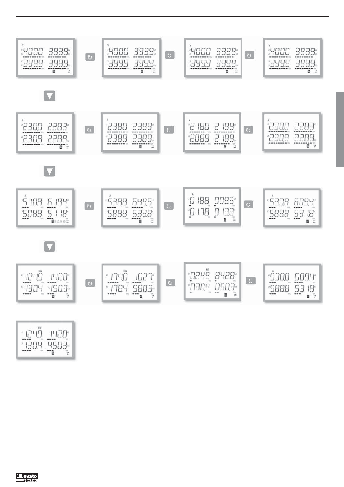
NAVIGAZIONE FRA LE PAGINE DEL DISPLAY
Tensioni concatenate
IN = Valore istantaneo HI = Valore massimo LO = Valore minimo AV = Valore medio
I422 GB I 10 17 31100212
Tensioni di fase
IN = Valore istantaneo HI = Valore massimo LO = Valore minimo AV = Valore medio
Correnti di fase e neutro
I
IN = Valore istantaneo HI = Valore massimo LO = Valore minimo AV = Valore medio
Potenza attiva di fase e totale
IN = Valore istantaneo HI = Valore massimo LO = Valore minimo AV = Valore medio
MD = Valore Max Demand
17
Page 18
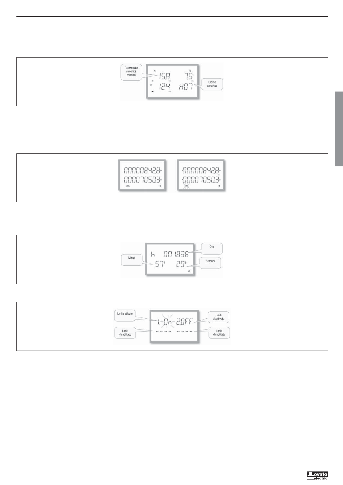
INDICAZIONE ANALISI ARMONICA
– Nel DMG100-110 è disponibile l’analisi armonica di fase fino al 15.mo ordine delle seguenti misure:
•
tensioni concatenate
•
tensioni di fase
•
correnti
– Per attivare l’analisi armonica è necessario impostare il parametro P02.12 = THD/HAR.
– Con P02.12 = THD viene visualizzato solo il THD delle misure sopracitate.
I422 GB I 10 17 31100212
INDICAZIONE CONTATORI ENERGIA
– Per le misure di energia ci sono 5 pagine dedicate.
•
Energia attiva importata ed esportata
•
Energia reattiva induttiva o capacitiva
•
Energia apparente.
– Ogni pagina visualizza il valore totale e parziale (azzerabili da menu comandi).
– Se l’unità di misura è accesa fissa significa che il contatore in questione è quello dell’energia importata (positiva). Impostando il parametro P02.09 su ON è possibile abilitare anche la visualizzazione delle energie
esportate (negative). Queste energie vengono evidenziate dalla unità di misura lampeggiante, e sono visualizzate successivamente a quelle importate premendo
.
I
Energia attiva importata Energia attiva esportata
– Se viene abilitata la visualizzazione delle energie per singola fase (P02.10=ON), allora per ogni potenza verranno visualizzate tre pagine indipendenti aggiuntive, una per ciascuna fase, comprendenti l’energia totale e
parziale.
INDICAZIONE CONTAORE
– Se il contaore è abilitato (vedere menu P05) il DMG100-110 visualizza la pagina contaore con il formato indicato in figura:
INDICAZIONE STATO LIMITI (LIMX)
– Se i limiti sono abilitati (vedere menu P08) il DMG100-110 visualizza la pagina con il relativo stato e con il formato indicato in figura:
– Con limite attivato la scritta ON lampeggia, mentre se il limite è disattivato la scritta OFF è fissa. Se un limite non è programmato compaiono i trattini.
18
Page 19
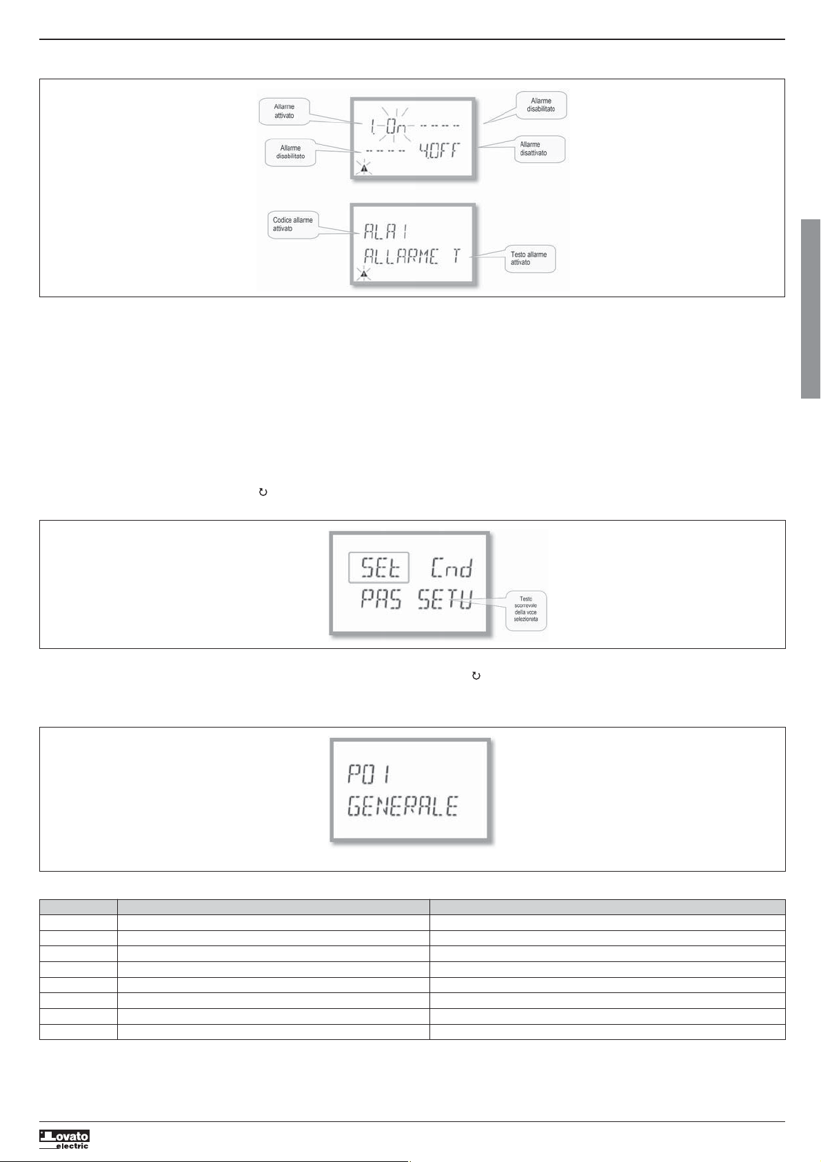
INDICAZIONE ALLARMI
– Se gli allarmi sono abilitati (vedere menu P09) il DMG100-110 visualizza la pagina con il relativo stato e con il formato indicato in figura:
I422 GB I 10 17 31100212
– Con Allarme attivato la scritta ON lampeggia con il simbolo del triangolo, mentre se l’allarme non è attivo la scritta OFF è fissa.
– Se un allarme non è programmato compaiono i trattini. Dopo circa 3s appare la scritta scorrevole con il testo dell’allarme programmato al parametro P09.n.05.
– Con più allarmi attivi il testo del relativo allarme viene visualizzato in modo alterno.
– Tramite l’apposito parametro P02.14 del menu utilità, è possibile fare in modo che la retroilluminazione del display lampeggi in caso di allarme per evidenziare la presenza dell’anomalia.
– Il reset degli allarmi è condizionato alla impostazione del parametro P09.n.03, che definisce se può essere automatico allo scomparire delle condizioni di allarme o se necessita di un azzeramento manuale tramite
menu comandi (C.07).
MENU PRINCIPALE
Per accedere al menu principale:
– Premere il tasto MENU. Viene visualizzato il menu principale (vedi figura) con le possibili scelte:
• SET – Accesso al menu impostazioni Setup
• CMD – Accesso al menu comandi
• PAS – Inserimento della password
– La scelta selezionata lampeggia. Nel display alfanumerico scorre una scritta descrittiva della scelta effettuata.
– Se è necessario impostare la password, il menu si apre con la voce PAS già selezionata.
– Premere
– Se si vuole tornare alla visualizzazione misure premere di nuovo MENU.
IMPOSTAZIONE DEI PARAMETRI (SETUP) DAL PANNELLO FRONTALE
– Dalla normale visualizzazione misure, premere MENU per richiamare il menu principale, quindi selezionare SET e premere per accedere al menu impostazioni.
– Il display indica il primo livello di menu P.01 nel display in alto a sinistra, con la selezione 01 lampeggiante.
– Selezionare il menu desiderato (P.01, P.02, P.03) tramite i tasti
– Se si vuole uscire e tornare alla visualizzazione misure, premere MENU.
per selezionare la voce voluta e poi premere per confermare la scelta.
. Mentre si seleziona, il display alfanumerico riporta una breve descrizione scorrevole del menu attualmente selezionato.
I
Impostazione: selezione menu
– Nella seguente tabella sono elencati i menu disponibili :
Cod. MENU DESCRIZIONE
P01 GENERALE Dati caratteristici dell’impianto
P02 UTILITA’ Lingua, luminosità, display ecc.
P03 PASSWORD Abilitazione protezione accesso
P04 INTEGRAZIONE Tempi di integrazione misure
P05 CONTAORE Abilitazione contaore
P07 COMUNICAZIONE Porte di comunicazione (DMG110)
P08 SOGLIE LIMITE (LIMn) Soglie sulle misure
P09 ALLARMI (ALAn) Messaggi di allarme
19
Page 20
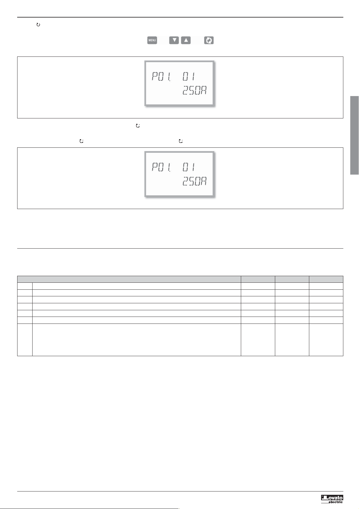
– Premere per accedere al menu selezionato.
– A questo punto è possibile selezionare il sottomenu (se presente) e poi il numero sequenziale del parametro, sempre con la funzione dei tasti come segue:
Indietro Incrementa/decrementa Avanti
I422 GB I 10 17 31100212
Impostazione: selezione numero del parametro
– Una volta impostato il numero del parametro desiderato, proseguendo con si passa alla modalità modifica del valore del parametro, che viene visualizzato nel display alfanumerico.
– Premendo
– Premendo contemporaneamente
– Premendo contemporaneamente
– Premendo MENU il valore del parametro viene memorizzato e si torna al livello precedente, cioè alla selezione parametri.
– Premere più volte MENU per uscire dalla impostazione e salvare i parametri. L’apparecchio si reinizializza.
– In alternativa, dall’interno della programmazione, tenendo premuto MENU per tre secondi consecutivi, si salvano le modifiche e si esce direttamente.
– Se non vengono premuti tasti per 2 minuti consecutivi, il menu setup viene abbandonato automaticamente e il sistema torna alla visualizzazione normale senza salvare i parametri.
– Rammentiamo che, per i soli dati di set-up modificabili da tastiera, è possibile fare una copia di sicurezza (backup) nella memoria eeprom del DMG100-110. Questi stessi dati all’occorrenza possono essere
TABELLA DEI PARAMETRI
– Di seguito vengono riportati tutti i parametri di programmazione disponibili in forma tabellare. Per ogni parametro sono indicati il range di impostazione possibile ed il default di fabbrica, oltre ad una spiegazione
M01 - GENERALE UdM Default Range
P01.01 Primario TA A 5 1-10000
P01.02 Secondario TA A 5 1-5
P01.03 Tensione nominale V 400 50-500000
P01.04 Utilizzo TV OFF OFF-ON
P01.05 Primario TV V 100 50-500000
P01.06 Secondario TV V 100 50-500
P01.07 Tipo di collegamento L1-L2-L3-N L1-L2-L3-N
L1-L2-L3
L1-L2-L3-N BIL
L1-L2-L3 BIL
L1-N-L2
L1-N
P01.01 – Corrente nominale del primario dei TA.
P01.02 – Corrente del secondario dei TA.
P01.03 – Tensione nominale dell’impianto.
P01.04 – Programmare ad ON se vengono utilizzati dei TV. Se programmato ad OFF i successivi due parametri vengono ignorati.
P01.05 – Tensione nominale primario TV.
P01.06 – Tensione nominale secondario TV.
P01.07 – Impostare concordemente allo schema di collegamento utilizzato. Vedere Schemi di collegamento alla fine del manuale.
o
il valore del parametro viene modificato all’interno del range previsto.
ripristinati (restore) nella memoria di lavoro. I comandi di copia di sicurezza e ripristino dei dati sono disponibili nel Menu comandi.
della funzionalità del parametro. La descrizione del parametro visibile sul display può in qualche caso differire da quanto riportato in tabella a causa del ridotto numero di caratteri disponibile. Il codice del
parametro vale comunque come riferimento.
e
il valore viene riportato immediatamente al valore di default di fabbrica.
e il valore viene impostato al minimo possibile, mentre con e al massimo possibile.
Impostazione valore del parametro
I
20
Page 21
M02 - UTILITÁ UdM Default Range
P02.01 Lingua English English
Italiano
Francais
Espanol
Portuguese
Deutsch
P02.02 Retroill. display alta % 100 0-100
P02.03 Retroill. display bassa % 30 0-50
P02.04 Tempo passaggio a retroilluminazione bassa s 30 5-600
P02.05 Ritorno a pagina di default s 60 OFF / 10-600
P02.06 Pagina di default VL-L VL-L / VL-N …
I422 GB I 10 17 31100212
P02.07 Sotto-pagina di default INST INST / HI / LO /
AVG / MD
P02.08 Tempo di aggiornamento display s 0.5 0.1 – 5.0
P02.09 Misura energie esportate OFF OFF-ON
P02.10 Misura energie per fase OFF OFF-ON
P02.11 Misura asimmetrie OFF OFF-ON
P02.12 Misura THD/Armoniche OFF OFF-THD-THD/HAR
P02.13 Misura sbilanciamento potenze OFF OFF-ON
P02.14 Lampeggio display in caso di allarme OFF OFF-ON
P02.05 – Se impostato ad OFF il display rimane sempre nella pagina dove è stato lasciato dall’utente. Se impostato ad un valore, dopo questo tempo il display ritorna alla pagina impostata con P02.06.
P02.06 – Numero della pagina alla quale il display ritorna automaticamente una volta che è trascorso il tempo P02.05 dall’ultima pressione di un tasto.
P02.07 – Tipo di sotto-pagina alla quale il display torna dopo trascorso P02.05.
P02.09 – Abilita la misura e la visualizzazione delle energie esportate (generate verso la rete).
P02.10 – Abilita la misura e la visualizzazione delle energie per singola fase.
P02.11 – Abilita la misura e la visualizzazione delle asimmetrie di tensione e di corrente.
P02.12 – Abilita la misura e la visualizzazione dei THD (distorsione armonica %) di tensione e di corrente.
P02.13 – Abilita il calcolo e la visualizzazione dello sbilanciamento fra le potenze di fase.
P02.14 – In presenza di un allarme la back light del display lampeggia per evidenziare l’anomalia.
M03 - PASSWORD UdM Default Range
P03.01 Utilizzo password OFF OFF-ON
P03.02 Password livello Utente 1000 0-9999
P03.03 Password livello Avanzato 2000 0-9999
P03.01 – Se impostato ad OFF, la gestione delle password è disabilitata e l’accesso alle impostazioni e al menu comandi è libero.
P03.02 – Con P03.01 attivo, valore da specificare per attivare l’accesso a livello utente. Vedere capitolo Accesso tramite password.
P03.03 – Come P03.02, riferito all’accesso livello Avanzato.
M04 - INTEGRAZIONE UdM Default Range
P04.01 Modo integrazione Scorr. Fisso
Scorrevole
Bus (DMG110)
P04.02 Tempo integrazione potenze min 15 1-60
P04.03 Tempo integrazione correnti min 15 1-60
P04.04 Tempo di integrazione tensioni min 1 1-60
P04.05 Tempo di integrazione frequenza min 1 1-60
P04.01 – Selezione della modalità di calcolo delle misure integrate.
Fisso = Le misure istantanee vengono integrate per il tempo impostato. Ad ogni scadenza del tempo, la misura integrata viene aggiornata con il risultato dell’ultima integrazione.
Scorrevole = Le misure istantanee vengono integrate per un tempo = 1/15 del tempo impostato. Ad ogni scadenza di questo intervallo viene sostituito il valore più vecchio con il nuovo calcolato. La misura
integrata viene aggiornata ogni 1/15 del tempo impostato, considerando una finestra scorrevole nel tempo che comprende gli ultimi 15 valori calcolati, di lunghezza totale equivalente al tempo impostato.
Bus = Come modalità fisso, ma gli intervalli di integrazione sono scanditi da messaggi di sincronismo inviati sul bus seriale.(110)
P04.02 – Tempo integrazione misure AVG (media) per le potenze attiva, reattiva ed apparente.
P04.03, P04.04, P04.05 – Tempo integrazione misure AVG (media) per le relative grandezze.
M05 - CONTAORE UdM Default Range
P05.01 Abilitazione generale contaore ON OFF-ON
P05.02 Abilitazione contaore parziale ON OFF-ON-LIMx
P05.03 Numero canale (x) 1 1-4
P05.01 – Se OFF i contaore sono disabilitati e la pagina di misura dei contaore non viene visualizzata.
P05.02 – Se OFF il contaore parziale non viene incrementato. Se ON viene incrementato quando il multimetro è alimentato. Se abbinato ad una delle variabili interne (LIMn) viene incrementato solo quando questa
condizione è vera.
P05.03 – Numero del canale (x) della variabile interna eventualmente usato nel parametro precedente. Esempio: Se il contaore parziale deve contare il tempo per cui una misura è oltre una certa soglia, definita dal
limite LIM3, programmare LIMx nel parametro precedente e specificare 3 in questo parametro.
I
21
Page 22
M07 - COMUNICAZIONE (solo DMG110) UdM Default Range
P07.01 Indirizzo seriale nodo 01 01-255
P07.02 Velocità seriale bps 9600 1200
2400
4800
9600
19200
38400
57600
115200
P07.03 Formato dati 8 bit – n 8 bit, no parità
8 bit, dispari
8bit, pari
7 bit, dispari
I422 GB I 10 17 31100212
7 bit, pari
P07.04 Bit di stop 1 1-2
P07.05 Protocollo Modbus RTU Modbus RTU
Modbus ASCII
P07.n.01 – Indirizzo seriale (nodo) del protocollo di comunicazione.
P07.n.02 – Velocità di trasmissione della porta di comunicazione.
P07.n.03 – Formato dati. Impostazioni a 7 bit possibili solo per protocollo ASCII.
P07.n.04 – Numero bit di stop.
P07.n.05 – Scelta del protocollo di comunicazione.
M08 - SOGLIE LIMITE (LIMn, n=1..4) UdM Default Range
P08.n.01 Misura di riferimento OFF OFF- (misure)
P08.n.02 Funzione Max Max – Min –
Min+Max
P08.n.03 Soglia superiore 0 -9999 - +9999
P08.n.04 Moltiplicatore x1 /100 – x10k
P08.n.05 Ritardo s 0 0.0 – 1000.0
P08.n.06 Soglia inferiore 0 -9999 - +9999
P08.n.07 Moltiplicatore x1 /100 – x10k
P08.n.08 Ritardo s 0 0.0 – 1000.0
P08.n.09 Stato a riposo OFF OFF-ON
P08.n.10 Memoria OFF OFF-ON
Nota: questo menu è diviso in 4 sezioni, per le soglie limite LIM1..4
P08.n.01 – Definisce a quale delle misure del multimetro applicare la soglia limite.
P08.n.02 – Definisce il funzionamento della soglia limite. Può essere:
P08.n.03 e P08.n.04 – Definiscono la soglia superiore, che è data dal valore di P08.n.03 moltiplicato per P08.n.04.
P08.n.05 – Ritardo di intervento sulla soglia superiore.
P08.n.06, P08.n.07, P08.n.08 – come sopra, riferiti alla soglia inferiore.
P08.n.09 – Permette di invertire lo stato del limite LIMn.
P08.n.10 – Definisce se la soglia rimane memorizzata e va azzerata manualmente (ON) o se si ripristina automaticamente (OFF).
Max = LIMn attivo quando la misura supera P08.n.03. P08.n.06 è la soglia di ripristino.
Min = LIMn attivo quando la misura è inferiore a P08.n.06. P08.n.03 è la soglia di ripristino.
Min+Max = LIMn attivo quando la misura è superiore a P08.n.03 oppure inferiore a P08.n.06.
I
M09 - ALLARMI (ALAn, n=1..4) Default Range
P09.n.01 Sorgente allarme OFF OFF-LIMx
P09.n.02 Numero canale (x) 1 1-4
P09.n.03 Memoria OFF OFF-ON
P09.n.04 Priorità Bassa Bassa - Alta
P09.n.05 Testo ALAn (testo 16 caratteri)
Nota: questo menu è diviso in 4 sezioni, per gli allarmi ALA1..4
P09.n.01 – Segnale che provoca l’allarme. Può essere il superamento di una soglia (LIMx).
P09.n.02 – Numero del canale x riferito al parametro precedente.
P09.n.03 – Definisce se l’ allarme rimane memorizzato e va azzerato manualmente (ON) o se si ripristina automaticamente (OFF).
P09.n.04 – Se l’allarme ha priorità alta, al suo verificarsi provoca lo spostamento automatico del display sulla pagina allarmi e viene visualizzato con l’icona di allarme. Se invece è impostato su priorità bassa, la
P09.n.05 – Testo libero dell’allarme. Max. 16 caratteri.
pagina non cambia e viene visualizzato con l’icona ‘informazioni’.
22
Page 23
MENU COMANDI
– Il menu comandi permette di eseguire operazioni saltuarie quali azzeramenti di misure, contatori, allarmi, ecc.
– Se è stata immessa la password per accesso avanzato, allora tramite il menu comandi è anche possibile effettuare delle operazioni automatiche utili ai fini della configurazione dello strumento.
– Nella seguente tabella sono riportate le funzioni disponibili con il menu comandi, divise a seconda del livello di accesso necessario.
Cod. COMANDO LIVELLO ACCESSO DESCRIZIONE
C.01 RESET HI-LO Utente / Avanzato Azzera i valori di picco HI e LO di tutte le misure
C.02 AZZERAMENTO MAX DEMAND Utente / Avanzato Azzera i valori Max demand di tutte le misure
C.03 AZZERAMENTO ENERGIE PARZIALI Utente / Avanzato Azzeramento dei contatori di energia parziali
C.04 AZZERAMENTO CONTAORE PARZIALI Utente / Avanzato Azzeramento dei contaore parziali
C.07 AZZERAMENTO ALLARMI Utente / Avanzato Azzeramento allarmi con memoria
C.08 AZZERAMENTO LIMITI Utente / Avanzato Azzeramento soglie limite con memoria
C.11 AZZERAMENTO ENERGIE TOTALI Avanzato Azzeramento dei contatori di energia totali e parziali
I422 GB I 10 17 31100212
C.12 AZZERAMENTO CONTAORE TOTALI Avanzato Azzeramento dei contaore totali
C.13 PARAMETRI A DEFAULT Avanzato Ripristina tutte le impostazioni ai valori di default di fabbrica
C.14 BACKUP PARAMETRI Avanzato Salva una copia di sicurezza (backup) delle impostazioni
C.15 RIPRISTINO PARAMETRI Avanzato Ricarica le impostazioni dalla copia di sicurezza
C.16 TEST COLLEGAMENTO Avanzato Esegue il test per verificare la correttezza del collegamento del DMG.
– Una volta selezionato il comando desiderato, premere per eseguirlo. Lo strumento chiederà una conferma. Premendo nuovamente il comando verrà eseguito.
– Per annullare l’esecuzione di un comando selezionato premere MENU.
– Per abbandonare il menu comandi premere MENU.
TEST DI COLLEGAMENTO
– Il test di collegamento consente di verificare se l’installazione del multimetro è stata effettuata correttamente.
– Per poter eseguire il test, il multimetro deve essere inserito in un impianto attivo con le seguenti condizioni:
• sistema trifase con presenza di tutte le fasi (V > 50VAC L-N)
• corrente minima circolante su ciascuna fase> 1% del fondo scala del TA impostato
• verso positivo delle energie (cioè in un comune impianto dove il carico induttivo assorbe energia dalla fornitura)
– Per lanciare l’esecuzione del test, entrare nel menu comandi e selezionare il comando C.16 secondo le istruzioni del capitolo Menu comandi.
– Il test consente di verificare i seguenti punti:
• lettura delle tre tensioni
• sequenza delle fasi
• sbilanciamento delle tensioni
• inversione della polarità di uno o più TA
• scambio delle fasi fra tensioni/correnti
– Se il test non viene superato, il display visualizza la ragione dell’errore.
Vedere capitolo Test collegamento
I
23
Page 24
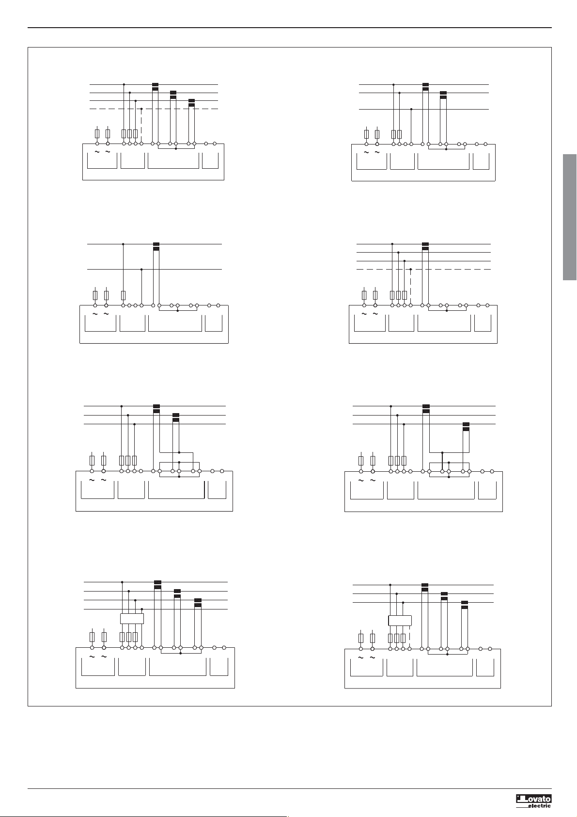
SCHEMI DI COLLEGAMENTO
I422 GB I 10 17 31100212
Connessione trifase con o senza neutro
P01.07 = L1-L2-L3-N L1-L2-L3
V1 VNV2 V3
VOLTAGE
TA/CT1
S1
S2
I1
S2S1
L1
L2
L3
N
100...240VAC
110...250VDC
---
A1
AUX SUPPLY
+
A2
Connessione monofase
P01.07 = L1-N
V1 VNV2 V3
VOLTAGE
TA/CT1
S1
I1
S2
S2S1
L1
N
100...240VAC
110...250VDC
---
A1
AUX SUPPLY
+
A2
TA/CT2
S2S1
S1 S2 S1 S2
CURRENT
S1 S2 S1 S2
I2
CURRENT
TA/CT3
Connessione bifase
P01.07 = L1-N-L2
V1 VNV2 V3
VOLTAGE
V1 VNV2 V3
VOLTAGE
TA/CT1
S2
S1
I1
TA/CT1
S2
S1
I1
TA/CT2
S2S1
CURRENT
S2S1
CURRENT
S2S1
S1 S2 S1 S2
I3I2
S1 S2 S1 S2
I2
L
O
A
D
AB
RS485
I
L
O
A
D
A B
I3
RS485
L
O
A
S2S1
I3I2
D
A B
RS485
L1
L2
N
100...240VAC
110...250VDC
---
A1
AUX SUPPLY
+
A2
Connessione trifase bilanciata con o senza neutro
P01.07 = L1-L2-L3-N-BIL L1-L2-L3-BIL
L
O
A
D
AB
I3
RS485
L1
L2
L3
N
100...240VAC
110...250VDC
---
A1
AUX SUPPLY
+
A2
Connessione ARON 3 fasi senza neutro
P01.07 = L1-L2-L3
V1 VNV2 V3
VOLTAGE
TA/CT1
S1
I1
S2
TA/CT2
S2S1
CURRENT
L1
L2
L3
100...240VAC
110...250VDC
A1
AUX SUPPLY
+
---
A2
Connessione trifase con neutro mediante TV
Impostare P01.04, P01.05 e P01.06
P01.07 = L1-L2-L3-N
TV/VT
VOLTAGE
TA/CT1
S1
S2
I1
TA/CT2
S2S1
CURRENT
L1
L2
L3
N
100...240VAC
110...250VDC
A1
AUX SUPPLY
V1 VNV2 V3
+
---
A2
S2S1
S1 S2 S1 S2
TA/CT3
S2S1
S1 S2 S1 S2
I2
Connessione ARON 3 fasi senza neutro
P01.07 = L1-L2-L3
VOLTAGE
TA/CT1
S1
I1
S2
S2S1
S1 S2 S1 S2
CURRENT
TA/CT3
L
O
A
S2S1
I3I2
D
A B
RS485
L
O
A
D
A B
I3I2
RS485
L1
L2
L3
N
100...240VAC
110...250VDC
---
A1
AUX SUPPLY
V1 VNV2 V3
+
A2
Connessione trifase senza neutro mediante TV
Impostare P01.04, P01.05 e P01.06
P01.07 = L1-L2-L3
TV/VT
V1 VNV2 V3
VOLTAGE
TA/CT1
S2
S1
I1
TA/CT2
S2S1
CURRENT
TA/CT3
S2S1
S1 S2 S1 S2
L
O
A
S2S1
I3I2
D
A B
RS485
L
O
A
S2S1
I3
D
A B
RS485
L1
L2
L3
100...240VAC
110...250VDC
---
A1
AUX SUPPLY
+
A2
NOTE
1. Fusibili raccomandati:
alimentazione ausiliaria e ingresso misura tensione: F1A (rapido).
2. I morsetti S2 sono internamente connessi fra di loro.
3. Utilizzare TA di classe 1. Per DMG110, se la tensione dell'impianto è VLN >300V, vanno utilizzati TA che garantiscono il doppio isolamento (classe 2).
24
Page 25
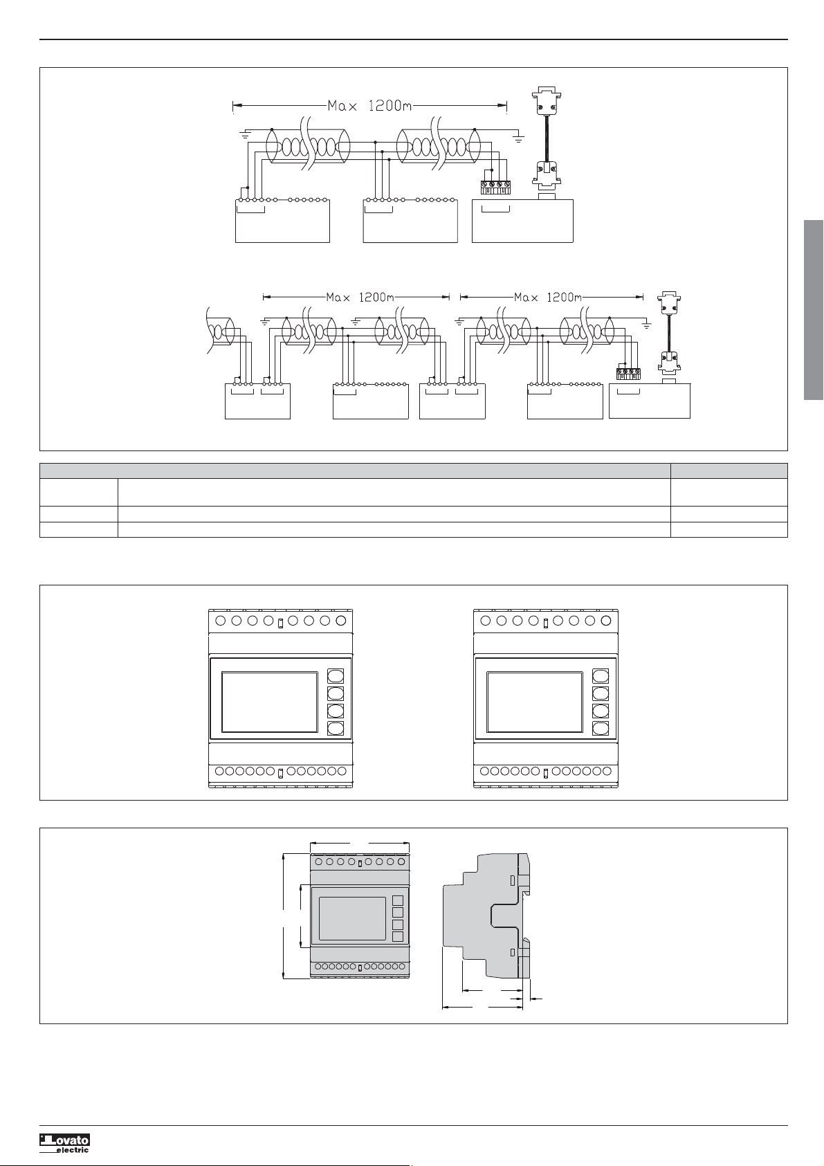
CONNESSIONE PC-DMG110.. MEDIANTE INTERFACCIA RS485
PC
Cable
51C4
SGBTR A
Interface converter
RS232/485
PX1
I422 GB I 10 17 31100212
SG
ABTR
RS485
DMG110 n°31
TR SGAB
RS485
DMG110 n°1
PC
Repeat this wiring diagram
up to 255 devices
TR
TR SGAB SGAB
Interface
converter
RS232/485
PX1
TR ABSG
RS485
DMG110
Device addresses n° 31-60
BTR A SG BTR A SG
Interface
converter
RS232/485
PX1
Set as repeaterSet as repeater
TRSGSGBA
RS485
DMG110
Device addresses n° 1-30
TR A B
Interface converter
RS232/485
PX1
Controllo remoto
Codici Descrizione Peso kg
ordinazione
4PX1 Convertitore RS232/RS-485 galvanicamente isolato alimentatore 220…240VAC. 0,600
51C4 Cavo di connessione PC Convertitore RS232/RS-485 lunghezza 1,80 metri. 0,147
Convertitore da tavolo RS232/RS-485 optoisolato, 38.400 Baud-rate max, gestione automatica o manuale della linea di TRASMIT, alimentazione 220…240Vac ±10% oppure 110…120Vac a richiesta .
DISPOSIZIONE MORSETTI
DMG100 DMG110
Cable
51C4
I
A1 A2 V2V1 V3 VN
DIMENSIONI MECCANICHE E FORATURA PANNELLO (mm)
S1
90
I1 I2
S2
45
S1 S1
S2
A1 A2
I3
S2
TR
SGBA
I1 I2
S1
V2V1 V3 VN
S1 S1
S2
I3
S2
S2
72
43.7
58
5
25
Page 26

CARATTERISTICHE TECNICHE
Alimentazione
Tensione nominale Us 100 - 240V
110 - 250V=
Limiti di funzionamento 90 - 264V
93,5 - 300V=
Frequenza 45 - 66Hz
Potenza assorbita/dissipata DMG100 0,5W – 1,5VA
Tempo di immunità alla DMG100 >= 40ms
microinterruzione DMG110 >= 30ms
Fusibili raccomandati F1A (rapidi)
I422 GB I 10 17 31100212
Ingresso voltmetrico
Tensione nominale Ue max 600VAC L-L (346VAC L-N)
Campo di misura 90…720V L-L (50...415VAC L-N)
Campo di frequenza 45…65Hz
Tipo di misura Vero valore efficace (TRMS)
Impedenza dell’ingresso di misura L-N - L-L > 8MΩ
Modalità di collegamento Linea monofase, bifase, trifase con o senza neutro
e trifase bilanciato
Fusibili raccomandati F1A (rapidi)
Ingressi amperometrici
Corrente nominale Ie 1A
Campo di misura Per scala 5A: 0,025 - 6A
Per scala 1A: 0,025 – 1,2A
Tipo di ingresso Shunt alimentati mediante trasformatore di
corrente esterno (bassa tensione) 5A max.
Tipo di misura Vero valore efficace (RMS)
Limite termico permanente +20% Ie
Limite termico di breve durata 50A per 1 secondo
Autoconsumo (per fase) ≤0,6VA
Precisione misure
Condizioni di misura
Temperatura +23°C ±2°C
Tensione (fase - neutro) ± 0,5% (50…415V
Tensione (fase - fase) ± 0,5% (90…720V
Corrente (TA /5) ± 0,5% (0,1…1,2In) ±0,5 digit
Energia attiva Classe 1 (IEC/EN 62053-21)
Energia reattiva Classe 2 (IEC/EN 62053-23)
Errori addizionali
Temperatura 0,05%/°K per V, A, W
DMG110 0,8W – 2,2VA
o 5A
) ±0,5 digit
) ±0,5 digit
Isolamento
Tensione nominale d’isolamento Ui 600V
Tensione nomi. di tenuta a impulso Uimp 9,5kV
Tensione di tenuta a frequenza d’esercizio 5,2kV
Condizioni ambientali
Temperatura d’impiego -20 - +60°C
Temperatura di stoccaggio -30 - +80°C
Umidità relativa <80% (IEC/EN 60068-2-78)
Grado di inquinamento ambiente massimo 2
Categoria di sovratensione 3
Categoria di misura III
Sequenza climatica Z/ABDM (IEC/EN 60068-2-61)
Resistenza agli urti 15g (IEC/EN 60068-2-27)
Resistenza alle vibrazioni 0,7g (IEC/EN 60068-2-6)
Connessioni circuito alimentazione/misura tensioni
Tipo di morsetti A vite (fissi)
N° morsetti 4 per controllo tensione / 2 per alimentazione
Sezione conduttori (min e max) 0,2 – 4,0 mm
Coppia di serraggio mors. 0,8Nm (7lbin)
Connessioni circuito misura correnti e RS485 (solo DMG110)
Tipo di morsetti A vite (fissi)
N° morsetti 6 per connessioni TA / 4 per connessioni RS485
Sezione conduttori (min e max) 0,2 - 2,5 mmq (24 - 12 AWG)
Coppia di serraggio mors. 0,44 Nm (4 lbin)
Contenitore
Esecuzione 4 moduli (DIN 43880)
Montaggio Guida 35mm (EN60715) o a vite a mezzo clip estraibili
Materiale Poliammide RAL 7035
Grado di protezione IP40 sul fronte / IP20 connessioni
Peso 300g
Omologazioni e conformità
Omologazioni ottenute cULus, RCM, EAC
Conformità alle norme IEC/EN 61010-1, IEC/EN 61010-2-030,
IEC/EN 61000-6-2, IEC/ EN 61000-6-3,
UL 61010-1, CSA C22.2 n° 61010-1,
UL 61010-2-030, CSA 22.2 n° 61010-2-030
UL Marking Use 75°C min copper (CU) conductor only
AWG Range: 18 - 12 AWG stranded or solid
Field Wiring Terminals Tightening Torque: 4.5lb.in
Flat panel mounting on a Type 1 enclosure
Alimentazione ausiliaria prelevata da un sistema con tensione fase-neutro ≤300V
2
(24 - 12 AWG)
I
CRONOLOGIA REVISIONI MANUALE
REV. DATA NOTE
00 26/01/2015 Prima versione
01 19/03/2015 Adeguati range P08.n.05 e P08.n.08 all’apparecchio
26
 Loading...