

Page 1
TLO
®
6955 VALJEAN AVE, VAN NUYS, CA 91406
PH: (818)994-6498 / FAX: (818)994-6458
/ www.louroe.com[email protected]
INSTALLATION AND OPERATING INSTRUCTIONS
DESCRIPTION
The TLO is a two-way speaker with microphone and re-entry horn for high volume
penetration. Weatherized for outdoor use, it is a microphone and speaker within one
housing. In operation, the TLO provides both listen and talkback capabilities
between the remote zone and Louroe base station, or with other compatible audio
receiving devices such as Louroe AOP-SP70.
OUTDOOR SPEAKER/MICROPHONE
MICROPHONE CONNECTION OF TLO
MODEL TLO
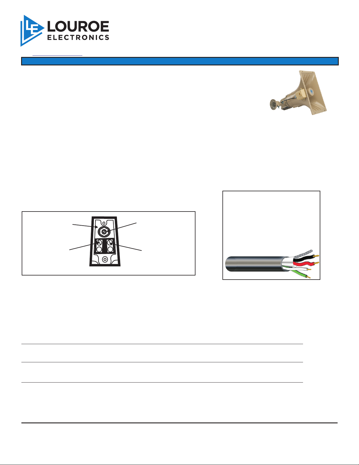
The short cable extending from the back of the TLO is the microphone connection and consists of three wires: red, black
and bare. Using recommended wiring (West Penn 356 or equivalent), make microphone connections using 20 gauge
wire nuts, and matching wire with , black with black and wire with wire. See diagram page 2.red red bare bare
SPEAKER CONNECTION OF TLO
Speaker connection is located near the rear of the TLO and has a plexiglass window. Remove window and connect the
speaker portion of West Penn 356 (green and white wires) to the two terminal screws marked 1 and 2.
Green speaker wire goes to position 2 (positive)
White speaker wire goes to position 1 (negative)
see diagram below
WIRING REQUIREMENTS
4 Conductor consisting of:
1 through 7
power tap settings
Speaker connection
(WHITE-negative)
2
1
1
3 5
+
set screw
6
7
Speaker connection
(GREEN-positive)
2
20 gauge with 22 gauge drain
(microphone connection)
+
unshielded, 18 gauge (speaker
connection)
West Penn 356 or equivalent
2 Conductor shielded,
2 Conductor
POWER TAP SETTINGS
Located above the speaker connection is a set screw with a dial numbered 1 through 7. Using a small screw
driver, adjust the set screw to correspond to the proper power tap setting with the following Louroe audio base
stations.
IF TLO IS CONNECTED TO BASE STATION MODELS:
Setting Wattage
AP-1TB through AP-16TB #1 1.8W
DG 12II and DG 25III 1 TLO per zone #4 15.0W
2-4 TLO’s per zone using MLA-6 Mixer #2 3.7W
If TLO is to be connected to Louroe AOP-SP70 conversion unit #2 3.7W
for interfacing with a DVR or PC Soundcard, use setting
Page 1 of 4
tlo inst 3/15
Page 2
INSTALLATION AND OPERATING INSTRUCTIONS
POSITIONING TLO
After TLO has been mounted to desired structure (wall, pole, etc.), horn should be tilted in a downward position.
This will protect the microphone element from water damage.
CONNECTING TLO TO A LOUROE BASE STATION
Model TLO is compatible with all Louroe™ audio base stations that feature two-way talk/listen communication. All
Louroe™ base stations contain terminal blocks for receiving both microphone and speaker connections from Model
TLO. For wiring and installation instructions, please refer to the specific Louroe™ Base Station being used.
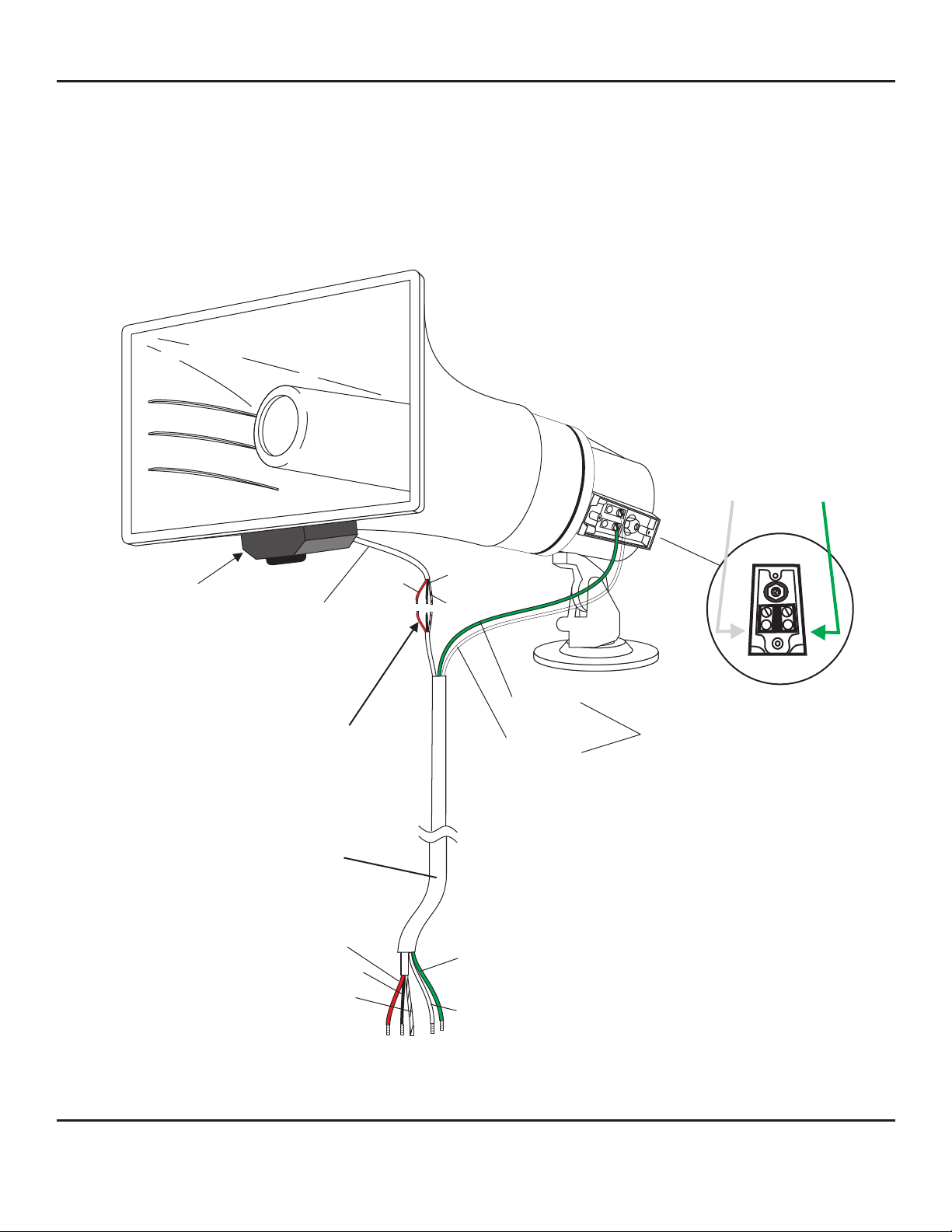
Speaker terminal screws
green wire to #2 (positive +)
white wire to #1 (ground -)
GROUND (-)
POSITIVE (+)
MICROPHONE
HOUSING
Microphone connection
using three wire nuts
Red = 12Vdc
Black = Audio Output
Bare = Ground
MICROPHONE
CONNECTION
Connects to
Terminals A, B, C
of Louroe Base
Station
{
RED
MICROPHONE
CABLE
(A) RED
(B) BLACK
(C) BARE
to Louroe base station
BLACK
BARE
WHITE
(GROUND)
GREEN
(POSITIVE)
SPEAKER
2
1
3 5
1
6
7
2
Green = speaker (positive)
connects to terminal “SP” of base station
White = speaker (negative)
connects to terminal “G” of base station
Refer to the specific base station instructions for connections
LOUROE ELECTRONICS™ 6 9 5 5 VALJEAN AVENUE, VAN NUYS, CA 91406 TEL (818) 994-6498 FAX 994-6458
website: www.louroe.com e-mail: [email protected]
Page 2 of 4
(818)
tlo inst 3/15
Page 3
ASPB
C
West Penn 358
or equivalent
INSTALLATION AND OPERATING INSTRUCTIONS
INTERCONNECTION DIAGRAM
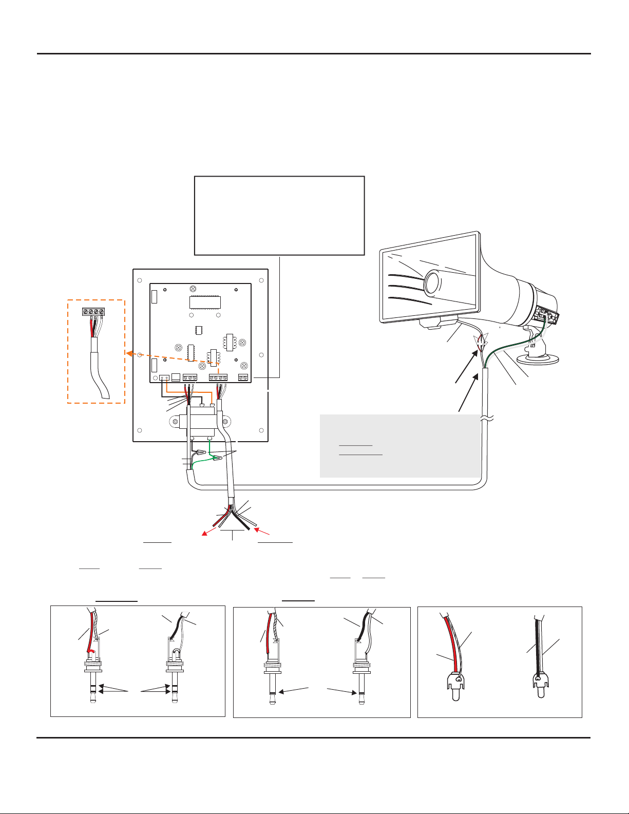
LOUROE MODEL AOP-SP70 SPEAKERPHONE CONVERSION UNIT,
AND LOUROE MODEL TLO SPEAKER/MICROPHONE
CONNECTION TO
DVR, IP NETWORK CAMERAS OR VIDEO SERVER
(BI-DIRECTIONAL AUDIO)
Using power supply (included), connect as
follows:
Positive 12Vdc connects to terminal marked
“+”
Negative 12Vdc or ground connects to
terminal marked “GND”(wire with white
stripes)
LOUROE MODEL AOP-SP70
EXT
EXT
SPKR
RED (A)
BLACK (B)
BARE (C)
SPKR SPKR
WHITE
GREEN
A B C CBA SP
Vdc+12
GND
WIRE NUTS
+
WIRING REQUIREMENTS FOR TLO
4 Conductor shielded cable
2 shielded 20 gauge and
2 unshielded 18 gauge,
20 gauge drain wire
West Penn 356 or equivalent
Model TLO is Designed For Outdoor
or Moist Applications
BLACK
RED
MICROPHONE
CABLE
Microphone connection
using three wire nuts
Red = 12Vdc
Black = Audio Output
Bare = Ground
BARE
GREEN SPEAKER
(POSITIVE)
WHITE SPEAKER
(GROUND)
(C) BARE
(B) RED
TO AUDIO IN OF DVR, ETC.
BLACK (C)
WHITE (SP)
TO AUDIO OUT OF DVR, ETC.
For connection to DVR, IP Network Camera, etc., solder the appropriate plug (RCA, 3.5mm
mono or 3.5mm stereo) to match the audio inputs of the receiving device as shown below.
Refer to IP Camera’s instruction to determine if 3.5mm audio is mono or stereo
3.5mm STEREO CONNECTION
Black Wire
Bare Wire
Red Wire
S
T
E
R
E
O
Audio In
LOUROE ELECTRONICS® 6 9 5 5 VALJEAN AVENUE, VAN NUYS, CA 91406 TEL (818) 994-6498 FAX 994-6458
White Wire
Audio Out
3.5mm MONO CONNECTION
Black Wire
Bare Wire
Red Wire
M
O
N
O
Audio In
Audio Out
RCA CONNECTION
White Wire
Red Wire
(818)
Bare Wire
Audio In
White Wire
Black Wire
Audio Out
website: www.louroe.com e-mail: [email protected]
tlo inst 3/15
Page 4
INSTALLATION AND OPERATING INSTRUCTIONS
MANUFACTURED
IN THE
IMPORTANT NOTICE
When this equipment is used as part of an
audio monitoring system, the law requires
that the public be given notice of AUDIO
MONITORING ON THE PREMISES. A
decal notice is included with each
microphone shipped.
Federal Law References:
Federal Regulations, US Code, Title 18.
Crime and Criminal Procedure, Sec 2510.
AUDIO
MONITORING
On
These Premises
®
SPECIFICATIONS (MICROPHONE)
Sensitivity -45 dBV/Pa
1 Pa = 94 dB SPL
Frequency Response 50 Hz to 15 kHz
Output Line Level (0 dBV, 600W @ 1kHz)
Current Drain 10mA
Supply Voltage 12 Vdc
SPECIFICATIONS (SPEAKER)
Power rating
Input
Frequency response
Sensitivity
Material
Dimensions
Dispersion
Weight
Shipping Weight
30W
70.7V constant
350 Hz to 14 kHz
109dB (Measured at 1m, 1W @ 1kHz)
Heavy Duty ABS Resin
11” W x 6 5/8” H x 12 3/4” D
105° x 72°
5 lbs 5 oz
7 lbs
LOUROE ELECTRONICS warrants that at the time of shipment products manufactured by LOUROE ELECTRONICS to be free of defects in material and workmanship.
Should a defect appear within one year (12 months) from date of shipment, LOUROE ELECTRONICS will, at its sole discretion, repair or replace the defective equipment.
This equipment shall not be accepted for repair or return without prior notification by LOUROE ELECTRONICS .
This warranty does not extend to any Louroe product that has been subjected to improper or incorrect installation, misuse, accident, or in violation of installation
instructions provided by LOUROE ELECTRONICS.
Returned shipments to LOUROE ELECTRONICS shall be at customer’s expense. LOUROE ELECTRONICS will return the equipment prepaid via best way.
®
®
®
LOUROE ELECTRONICS™ 6 9 5 5 VALJEAN AVENUE, VAN NUYS, CA 91406 TEL (818) 994-6498 FAX 994-6458
WARRANTY
®
®
®
(818)
website: www.louroe.com e-mail: [email protected]
Page 4 of 4
tlo inst 3/15
 Loading...