

Page 1
®
6955 VALJEAN AVE, VAN NUYS, CA 91406
PH: (818)994-6498 / FAX: (818)994-6458
/ www.louroe.com[email protected]
®
VERIFACT CGC
MICROPHONE
INSTALLATION AND OPERATING INSTRUCTIONS
DESCRIPTION
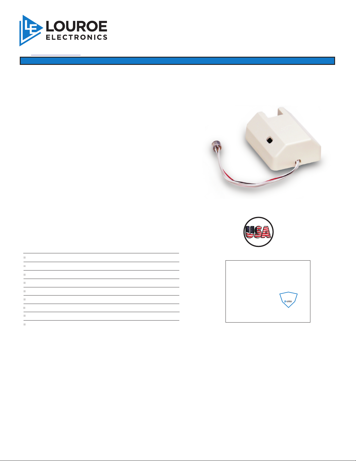
The Verifact CGC is an omni-directional, low
®
impedance, electret condenser microphone with built-in
preamp and automatic gain control. It can pick up
normal sounds approximately 25 ft. away, or within a 50
ft. diameter circle. It’s built-in limiter prevents the output
signal to be overdriven thus minimizing distortion.
Verifact C-AGC produces line level output (0 dB) and
®
can be located up to 1,000’ from the Louroe base
station. It is designed for mounting in a special or
customized housing. The Verifact CGC is compatible
®
with all Louroe Audio Base Stations or Louroe Audio
Interface Adapters.
NOTE:
Verifact CGC Microphone is NOT
®
recommended for outdoor use or in areas with
high moisture content.
VERIFACT CGC
U
T
C
A
F
U
N
A
M
®
R
E
D
I
N
T
H
E
SPECIFICATIONS
Microphone Sensitivity
Frequency response
Output
Current drain
Supply voltage 12 Vdc
Output gain
Microphone housing
Dimensions
Weight
Shipping Weight
LOUROE ELECTRONICS warrants that at the time of shipment products manufactured by LOUROE ELECTRONICS to be free of defects in material and workmanship.
Should a defect appear within one year (12 months) from date of shipment, LOUROE ELECTRONICS will, at its sole discretion, repair or replace the defective equipment.
This equipment shall not be accepted for repair or return without prior notification by LOUROE ELECTRONICS .
This warranty does not extend to any Louroe product that has been subjected to improper or incorrect installation, misuse, accident, or in violation of installation
instructions provided by LOUROE ELECTRONICS.
Returned shipments to LOUROE ELECTRONICS shall be at customer’s expense. LOUROE ELECTRONICS will return the equipment prepaid via best way.
®
-45dB
50Hz to 8kHz
Line Level (0 dB, 1 kW at 1 Khz )
10 mA
+10dB
High impact ABS
2 5/8”L x 2 1/8”W x 1 1/16”H
1.5 oz
1lb
WARRANTY
®
®
IMPORTANT NOTICE
When this equipment is used as part of an
audio monitoring system, the law requires
that the public be given notice of AUDIO
MONITORING ON THE PREMISES. A
deca l noti ce is included with each
microphone shipped.
Federal Law References:
Federal Regulations, US Code, Title 18.
Crime and Criminal Procedure, Sec 2510.
®
®
®
AUDIO
MONITORING
On
These Premises
®
Page 1 of 4
Cgc_mic_inst_12/14
Page 2

INSTALLATION AND OPERATING INSTRUCTIONS
MECHANICAL INSTALLATION
Microphone pre-amp is mounted in a protective plastic housing with openings for wire connection and microphone
sensitivity adjustment. If microphone is to be mounted in a special housing, a black grommet is included for optional use
in securing the microphone element to the inside of a camera housing or special housing. A 1/8” minimum opening must
be provided for microphone pickup. Microphone should be located within 4’ to 6’ of the subject. Avoid ceiling mounts
in excess of 10’ in height.
ELECTRICAL CONNECTION
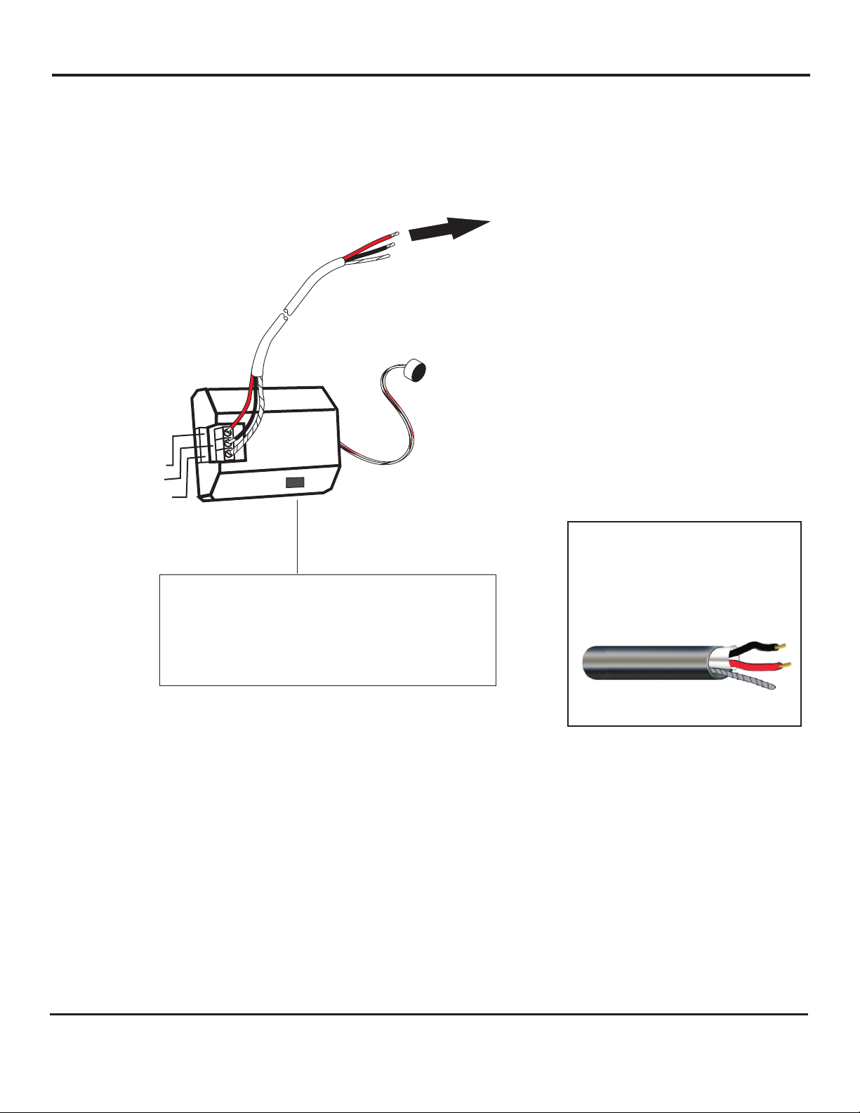
Verifact CGC Microphone will connect directly to any Louroe Base Station (AP Series or DG Series) or to the IF-1, IF-4
or IF-8 Interface Adapters. A small terminal block is located on the microphone pre-amp, and marked A, B, C:
®
A represents 12 Vdc (positive)
B represents Audio (Mic output)
C represents Ground (negative)
NOTE:
Verifact CGC Microphone is NOT recommended for
®
outdoor use or in areas with high moisture content.
CONNECTING VERIFACT CGC MICROPHONE TO A LOUROE RECEIVING DEVICE (BASE
®
STATION OR AUDIO INTERFACE ADAPTER)
After microphone connection has been made, run 2 conductor shielded cable to the Louroe Base Station or interface
adapter.
If Louroe Base Station is AP Series, DG-12/25 series, IF-1, IF-4 or IF-8:
RED wire to terminal A of base station
BLACK wire to terminal B of base station
BARE wire to terminal C of base station
CONNECTING VERIFACT CGC MICROPHONE DIRECTLY TO A DVR OR IP CAMERA
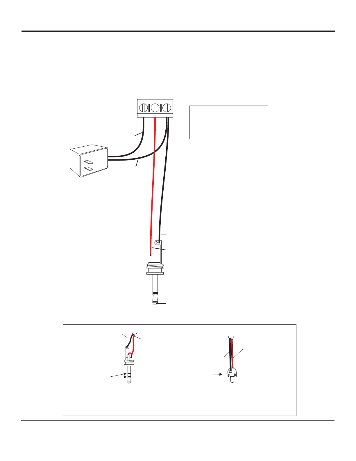
If a Louroe Audio Base Station or interface adapter is not used and Verifact CGC is to be connected
directly to a DVR or soundcard, etc. use the following procedure (See last page for interconnection diagram)
1) Apply 12 Vdc (100 mA minimum) to PC board’s terminals A and C, A is positive, C is
ground
2) Run a single conductor shielded cable 22 gauge with a 24 gauge drain wire to DVR or
IP Camera
3) Solder on an RCA connector with wire from terminal B of microphone going to the tip
of the plug, and wire from terminal C of microphone going to the sleeve of RCA plug.
4) Connect RCA plug into “Audio In” jack of DVR or soundcard.
®
®
NOTE: In the interconnection diagram, black wire is used instead of bare to represent ground.
If DVR’s audio input is 3.5mm (1/8”port), a 3.5mm adapter must be connected to one end of the RCA cable.
Check DVR manufacturer’s instructions to determine if 3.5mm audio input is mono or stereo.
LOUROE ELECTRONICS 6 9 5 5 VA L J E A N AVENUE, VAN NUYS, CA 91406 TEL (818) 994-6498 FAX 994-6458
®
website: www.louroe.com e-mail: [email protected]
Page 2 of 4
(818)
Cgc_mic_inst_12/14
Page 3
INTERCONNECTION DIAGRAM
CONNECTION DIAGRAM
A
B
C
A (12 Vdc)
B (Audio)
C (Ground)
L
INSTALLATION AND OPERATING INSTRUCTIONS
TO LOUROE BASE
STATION OR AUDIO
AUDIO INTERFACE
ADAPTER
If using recommended wiring (West Penn 452)
RED wire (12 Vdc) connects to Terminal A
BLACK wire (Audio) connects to Terminal B wire
(Ground) connects to Terminal C
N
BARE
WIRING REQUIREMENTS
2 Conductor shielded cable, 22
gauge with a 24 gauge drain wire
MICROPHONE GAIN ADJUSTMENT
The microphone has an audio output gain potentiometer.
Microphone is always shipped with a 0dB output. If it’s necessary
to change the gain of the microphone, insert a small screwdriver
into the potentiometer rotate clockwise to increase or
counterclockwise to decrease. Maximum gain is +10dB
NOTE: Unshielded cable is not
satisfactory for audio systems
West Penn 452 or equivalent
INSTALLATION TIPS
1. Use overall shielded audio cable only. West Penn 452, Belden 8451 or equivalent.
UNSHIELDED CABLE IS NOT SATISFACTORY FOR SOUND SYSTEMS.
2. When used at a cash register checkout, microphone should be installed closer to the customer rather than the cash
register, as the drawer sound could dominate the recording. It should be installed closest to the
area to be monitored and documented.
3. Avoid installing microphone near air vents, air conditioners, fans and other equipment that generate
high sound and air pressure.
4. If microphone is installed in a police interview room, room should be conditioned with any type of carpeting, acoustical
ceiling tiles, acoustical foam, etc. to reduce echo. This will enhance the quality of live and recorded audio.
5. The APR-1 and microphone should have a barrier or solid wall between them in order to avoid audio
feedback, especially when they are in close proximity to each other. If no barrier, microphone should be at least 25’
from APR-1 to avoid acoustical feedback.
LOUROE ELECTRONICS 6 9 5 5 VA L J E A N AVENUE, VAN NUYS, CA 91406 TEL (818) 994-6498 FAX 994-6458
®
website: www.louroe.com e-mail: [email protected]
Page 3 of 4
(818)
Cgc_mic_inst_12/14
Page 4
CONNECTING A LOUROE MICROPHONE DIRECTLY
TO AN IP CAMERA, ENCODER OR DVR WITH 3.5mm
12 Vdc POWER SUPPLY
INSTALLATION AND OPERATING INSTRUCTIONS
MONO AUDIO INPUT
MICROPHONE TERMINAL BLOCK
A
B
C
+12 Vdc
+
_
GROUND
A = 12Vdc Power
B = Audio Output
C = Ground
LOOP “C” WIRE THRU OPENING, THEN SOLDER
“B” WIRE
3.5mm MONO PLUG REMOVED
FROM JACKET
TO LINE LEVEL INPUT OF IP CAMERA OR
DVR WITH 3.5mm MONO AUDIO INPUT
OTHER PLUGS WIRING CONFIGURATION
Black Wire
Red Wire
S
T
E
R
E
O
Audio In
of receiver
3.5mm Stereo CONNECTION
Red Wire
Black Wire
R
C
A
Audio In
of receiver
RCA CONNECTION
LOUROE ELECTRONICS 6 9 5 5 VA L J E A N AVENUE, VAN NUYS, CA 91406 TEL (818) 994-6498 FAX 994-6458
®
website: www.louroe.com e-mail: [email protected]
Page 4 of 4
(818)
Cgc_mic_inst_12/14
 Loading...