

Page 1
IF-2/IF-4/IF-8
®
6955 VALJEAN AVE, VAN NUYS, CA 91406
PH: (818)994-6498 / FAX: (818)994-6458
/ www.louroe.com[email protected]
INSTALLATION AND OPERATING INSTRUCTIONS
DESCRIPTION
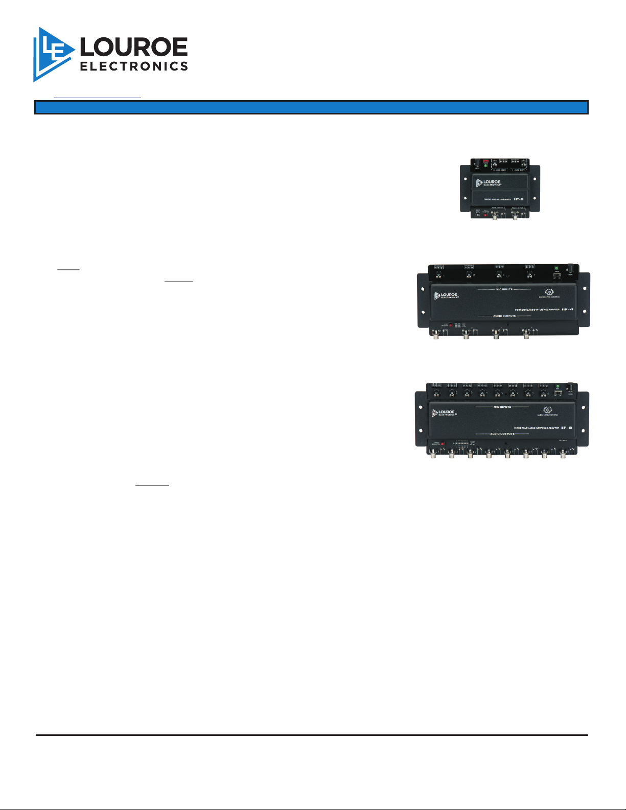
The LOUROE IF-2, IF-4 and IF-8 are two, four zone and eight zone audio
interface adapters designed for connecting up to two (IF-2), four (IF-4) or eight
(IF-8) Louroe microphones with:
! DVR’s
! IP Network Cameras with audio inputs
! Video Servers with audio inputs
! PC Sound Card Modules
The input side of the IF-2/IF-4/IF-8 has terminal blocks for receiving the wiring
from the microphones. The output side has RCA types of output. The
following cables and adaptors are included with each IF series.
RCA to RCA type - For connection to a DVR, etc. with RCA audio inputs.
RCA to 3.5mm mono type adaptor - For connection to an IP Network
Camera, etc. with a 3.5mm audio input
AUDIO INTERFACE ADAPTERS
IF-2 AUDIO
INTERFACE ADAPTER
(two audio inputs and outputs)
IF-4 AUDIO
INTERFACE ADAPTER
(four audio inputs and outputs)
These three units also contain individual “audio level control” potentiometers
for audio gain adjustment. Output from the Louroe microphone can be
increased 10dB or decreased -30dB.
WIRING CONNECTIONS
IF-8 AUDIO
MICROPHONE TO INPUT SIDE OF IF-2/IF-4/IF-8
INTERFACE ADAPTER
(eight audio inputs and outputs)
All Louroe microphones contain a terminal block
marked A, B, C
A = 12Vdc power (Red)
B = Audio output (Black)
C = Ground (Bare)
If using recommended wiring, connect as follows:
Red wire goes to Terminal A of microphone (12Vdc power)
Black wire goes to Terminal B of microphone (Audio Output)
Bare wire goes to Terminal C of microphone (Ground)
After all microphones have been connected, bring other end of wiring to the IF-2/IF-4/IF-8 location
and connect each microphone to the terminal blocks of the unit marked A, B, C. Be sure to properly
match wire colors. If using cable from other manufacturers, color code may vary.
LOUROE ELECTRONICS 69 5 5 VA L J E A N AVENUE, VAN NUYS, CA 91406 TEL (818) 994-6498 FAX 994-6458
®
website: www.louroe.com e-mail: [email protected]
Page 1 of 4
(818)
If_248_inst_3/15
Page 2

INSTALLATION AND OPERATING INSTRUCTIONS
CONNECTION BETWEEN IF-2/IF-4/IF-8 AND DVR (OR OTHER AUDIO RECEIVING DEVICES)
The output side of IF-2/IF-4/IF-8 has an RCA output per microphone with two types of connectors
1. RCA to RCA type cable; for connection to a DVR, etc. with RCA audio inputs
2. RCA to 3.5mm mono adaptor: for connection to a DVR, IP Network Camera or Video Server
that has 3.5mm audio inputs.
If the receiving device contains RCA type “audio in” jacks, then connect from Audio Out of IF-2/IF-4/IF-8 to
APPLYING POWER TO THE IF-2/IF-4/IF-8
Audio In of DVR, using the provided RCA connector cables.
If the receiving device contains 3.5mm mono audio inputs, connect 3.5mm RCA to mono adaptor to one
end of the RCA cable (supplied) and plug that end to the IP camera or video server. Connect the RCA
end of the cable to the output of the IF-2/IF-4/IF-8.
Included with the units are:
2, 4 or 8 RCA to RCA cables
2, 4 or 8 RCA to3.5mm mono adaptors
Included with the IF-2/IF-4/IF-8 is a power supply (120V/12Vdc). Connect the small end of the 90° female
plug into the 12Vdc jack, located on the input side. Then connect the two-prong large end into a
standard 110/120V electrical outlet.
Turn ON/OFF power switch, located behind green power LED to ON position. The green LED will illuminate,
indicating power to the system. The system will now provide audio to the DVR, Soundcard Module, IP
Network Camera, etc.
AUDIO LEVEL ADJUSTMENT
Located on the input side are potentiometers (round, with adjustment arrow) for each microphone. This is
for adjusting the audio gain and to prevent overdriving or underdriving the audio signal.
The adjustment arrows are shipped in the straight-up position. Turn slowly counterclockwise to lower
the gain, and clockwise to increase. This will provide the desired level of audio signal into the Audio
Receiving Device (DVR, Soundcard Module, etc.). A full turn clockwise increases the gain to 10dB. A
full turn counterclockwise will decrease the gain -30dB.
AUDIO TEST SWITCH
The purpose of this switch is to indicate the presence of audio and to assure the user that the IF-2/IF-4 or IF-
8 is driving the audio signals into the audio input of receiving device (DVR, IP Network Camera, Video
Server, Soundcard module, etc.)
Located on the audio output side of IF-2/IF-4/IF-8 is a DIP switch labeled Audio Test Switch. To the left
of the switch is a red LED marked Audio Indicator.
For testing:
1) Select a zone that has a microphone connected to the microphone terminal block.
IF-2 utilizes pins 1&2. IF-4 utilizes pins 1-4. IF-8 utilizes pins 1-8.
2) Push pin to the ON position. The red LED will illuminate, indicating audio is present. With
short bursts of audio, the LED will flicker and with continuous flow of audio LED
illumination is constant. Only one microphone can be tested at a time
NOTE: When testing is complete, all pins on DIP switch
NOTE: When testing is complete, all pins on DIP switch must be in the OFF position
LOUROE ELECTRONICS 69 5 5 VA L J E A N AVENUE, VAN NUYS, CA 91406 TEL (818) 994-6498 FAX 994-6458
®
website: www.louroe.com e-mail: [email protected]
Page 2 of 4
(818)
If_248_inst_3/15
Page 3
INSTALLATION AND OPERATING INSTRUCTIONS
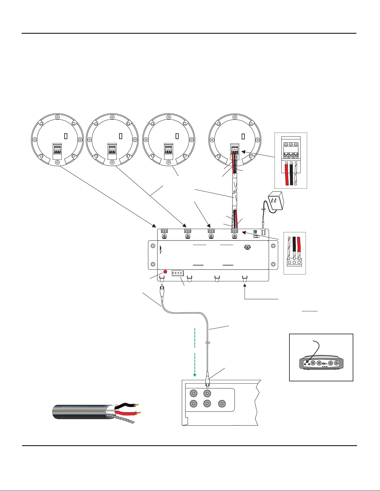
INTERCONNECTION DIAGRAM
FOR
CONNECTING LOUROE VERIFACT MICROPHONES
TO A DVR WITH MULTIPLE AUDIO INPUTS USING
LOUROE MODEL IF-2, IF-4 OR IF-8 AUDIO INTERFACE ADAPTER
(IF-4 used as an example)
Verifact™ A Microphone Shown
®
Back side of
VE RIF ACT A
VERIFACT A, B, C, D, D-V, E, K, L-DT
N
L
A B C
All Louroe microphones
®
VE RIF ACT A
A B C
N
L
are compatible with Louroe IF-2,
IF-4 and IF-8 Audio Interface Adapters
Verifact A Microphone shown as an example
®
with IF-4 Interface Adapter
Audio Indicator Light
Audio Out
LOUROE MODEL IF-4
AUDIO INTERFACE ADAPTER
(Connections for IF-2 and IF-8 are same as above)
IF-2 will accommodate
2 Louroe™ microphones
VE RIF ACT A
A B C
N
L
2 CONDUCTOR
SHIELDED
22 GAUGE
WEST PENN
452 OR EQUIV.
OUROE
L
LECTRONICS
E
ON RS
1 2 3 4
1
BLACK
BLACK
BARE
MIC INPUTS
AUDIO OUTPUTS
2
Audio Test Switch
RCA CABLE CONNECTS FROM
“AUDIO OUT” OF IF-4 TO
“AUDIO IN” OF DVR, ETC.
VE RIF ACT A
A B C
RED
FOUR ZONE AUDIO INTERFACE ADAPTER
3
N
L
BARE
R
RED
AUDIO LEVEL CONTROL
4
+12 Vdc POWER
SUPPLY (INCLUDED)
IF-4
11 1 1
Red - 12Vdc power
A
B
Black - Audio Output
C
Bare - Ground
B
C
A
RCA output
Use 3.5mm mono to RCA
cable of IF-4 for
connection to
Video Server or IP camera
audio input
IF-4 will accommodate up to
4 Louroe™ microphones
Audio Path
1 2 3 4
Audio In
IF-8 will accommodate up to
8 Louroe™ microphones
VIDEO SERVER
West Penn 452
AUDIO OUT
AUDIO IN
or equivalent
DVR WITH RCA TYPE AUDIO INPUTS
LOUROE ELECTRONICS 69 5 5 VA L J E A N AVENUE, VAN NUYS, CA 91406 TEL (818) 994-6498 FAX 994-6458
®
(818)
website: www.louroe.com e-mail: [email protected]
Page 3 of 4
If_248_inst_3/15
Page 4
MANUFACTURED
SPECIFICATIONS
IN THE
Input (3-pin terminal block)
Audio Input Impedance
Audio Output Impedance
Audio Output Gain
Line Level
20kW
IF-2 400W IF-4/8 600W @1kHz
+10dB
Power Requirements +12 Vdc, 500mA
Dimensions (IF-2)
Dimensions (IF-4/IF-8)
Weight
6 1/8”L x 4 5/8”W x 1 3/8”H
11 1/2”L x 4 3/4”W x 1 1/2”H
IF-2 7 oz
IF-4 12.5 oz
IF-8 13.5 oz
Shipping Weight
IF-2 1 lb
IF-4 2 lbs
IF-8 2 lbs
IMPORTANT NOTICE
When this equipment is used as part of an audio
monitoring system, the law requires that the public
be given notice of AUDIO MONITORING ON THE
PREMISES. A decal notice is included with each
microphone shipped.
Federal Law References:
Federal Regulations, US Code, Title 18. Crime
and Criminal Procedure, Sec 2510.
AUDIO
MONITORING
On
These Premises
®
LOUROE ELECTRONICS warrants that at the time of shipment products manufactured by LOUROE ELECTRONICS to be free of defects in material and workmanship.
Should a defect appear within one year (12 months) from date of shipment, LOUROE ELECTRONICS will, at its sole discretion, repair or replace the defective equipment.
This equipment shall not be accepted for repair or return without prior notification by LOUROE ELECTRONICS .
This warranty does not extend to any Louroe product that has been subjected to improper or incorrect installation, misuse, accident, or in violation of installation
instructions provided by LOUROE ELECTRONICS.
Returned shipments to LOUROE ELECTRONICS shall be at customer’s expense. LOUROE ELECTRONICS will return the equipment prepaid via best way.
LOUROE ELECTRONICS 69 5 5 VA L J E A N AVENUE, VAN NUYS, CA 91406 TEL (818) 994-6498 FAX 994-6458
®
®
®
®
WARRANTY
®
®
®
(818)
website: www.louroe.com e-mail: [email protected]
Page 4 of 4
If_248_inst_3/15
 Loading...