

Page 1
L
OUROE
E
6955 VALJEAN AVE, VAN NUYS, CA 91406
LEC TRON ICS
PH: (818)994-6498 / FAX: (818)994-6458
[email protected] / www.louroe.com
DCS-12V
REMOTE CALL STATION
INSTALLATION AND OPERATING INSTRUCTIONS
For Connection to Louroe Model AP-4CS, AP-8CS or
AP-12CS Alarming Base Station
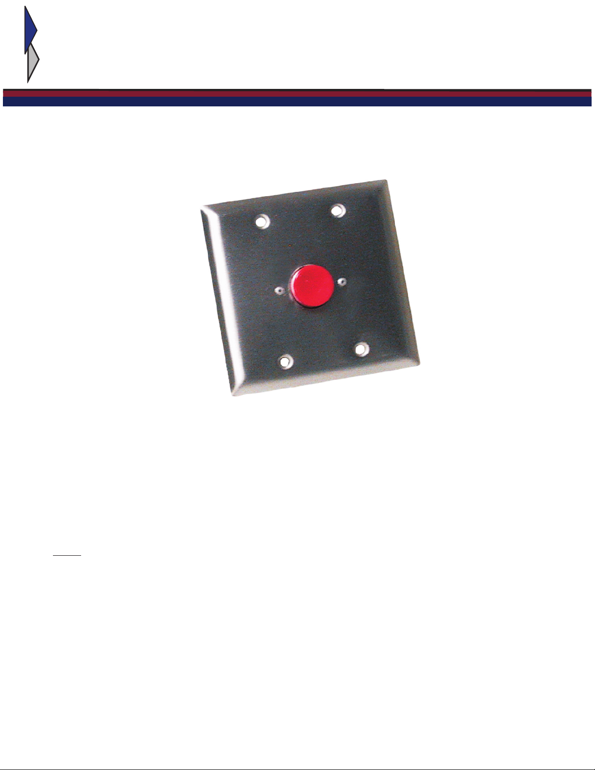
The DCS-12V is a remote call station with a 1” red pushbutton mounted to a 2-gang stainless
faceplate. It is part of a duress system that includes a Louroe alarming base station (Model AP-4CS,
AP-8CS or AP-12CS). When pushbutton is pressed the alarming base station is activated,
identifying the zone. The alarming base station contains a set of dry contact (one for each zone) that
can be used for activating a camera or other annunciation.
Note: The DCS-12V is compatible only with the three base stations listed above and does not
provide audio communications between the DCS-12V and the base station.
dcs 12v 408
Page 2
INSTALLATION AND OPERATING INSTRUCTIONS
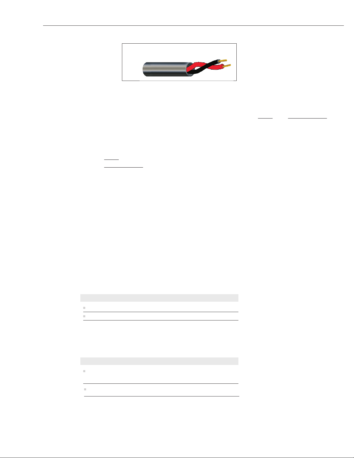
Activation only, no audio
Twisted pair 20 gauge
West Penn 222 or equivalent
INSTALLATION
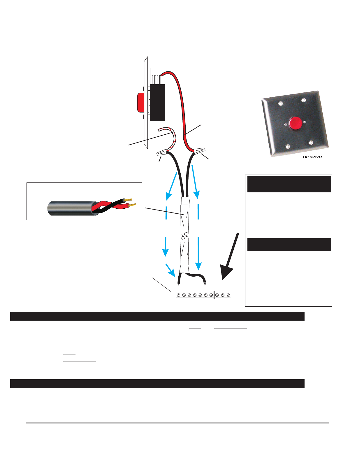
Located on the back side of the DCS-12V is a switch with two wires. RED and RED/WHITE.
Connect these two wires to a twisted pair, 22 gauge, using wire nuts. Extend the other end of
the twisted pair to the Louroe base station (AP-4CS, AP-8CS or AP-12CS). Rear panel of
base station contains a series of 7-pin terminal blocks. Pins are marked A, B, C, SP, G, AL,
and P.
1) Connect RED wire from DCS-12V to pin “AL” (Alarm) of back panel of base station.
2) Connect RED/WHITE wire from DCS-12V to pin “A” (12 Vdc) of back panel of base
station. The remaining 5 pins are not used with this application.
Located next to the 7-pin terminal block is a 3-pin relay closure terminal block for activating a
camera or other external device. The 3-pin terminal block is marked
CM - common contact
NC - normally closed
NO - Normally open
If this feature is to be used, connect the external device (camera, recorder, etc.) to pins “CM” and
“NO” of alarming base station, using a twisted pair, 20 gauge (West Penn 222 or equivalent).
When the Louroe base station is alarmed by the DCS-12V, a switch will close, activating the
external device. Models AP-4CS, AP-8CS and AP-12CS have both a manual reset and an
automatic reset for cancelling the activation. The auto reset can be adjusted for a time length of 3
seconds to 4 minutes. Refer to the Louroe AP-CS installation and operation instruction for
additional information.
SPECIFICATIONS
Pushbutton supply voltage 12 Vdc
Pushbutton actuator material Polycarbonate
SPECIFICATIONS ( )Mechanical
Faceplate
4 ½"L x 4 ½"W
stainless steel
Weight, net
LOUROE ELECTRONICS, 6955 VALJEAN AVE., VAN NUYS, CA 91406 (818) 994-6498 FAX 994-6458
Website: www.louroe.com Email: [email protected]
8 oz (227g)
dcs 12v 408
Page 1 of 2
Page 3
MODEL DCS-12V
SIDE VIEW
INSTALLATION AND OPERATING INSTRUCTIONS
WIRING CONNECTION
BETWEEN
LOUROE DCS-12V REMOTE CALL STATION
AND
LOUROE ALARMING BASE STATION
AP-4CS, AP-8CS OR AP-12CS
OPEN
NORMALLY
FACTORY INSTALLED
(WHITE/RED)
Activation only, no audio
Twisted pair 20 gauge
West Penn 222 or equivalent
Terminal Block of
WIRE NUT
AP-4CS,
AP-8CS,
or AP-12CS
Base Station
GROUND
TO
PIN
“A”
A B C SP G AL P
FACTORY INSTALLED
(RED)
WIRE NUT
TO
PIN
“AL”
CM NC NO
DCS-12V
REMOTE CALL STATION
Terminal Block
Identification
A - 12Vdc
B - Audio Output
C - Ground
SP - Speaker (+)
G - Speaker (-)
AL - Alarm
P - Parallel
(Used when paralleling two
base stations)
CM - Common
NC - Normally closed
NO - Normally open
CM, NC & NO pins are used for
activating a camera, etc. Refer
to manufacturers instruction for
wiring infomation
Wiring connection to Model DCS-12V Remote Call Station
Located on the back side of the DCS-12V is a switch with two wires. RED and RED/WHITE. Connect these two wires to a
twisted pair, 22 gauge, using wire nuts. Extend the other end of the twisted pair to the Louroe base station (AP-4CS, AP-8CS or
AP-12CS). Rear panel of base station contains a series of 7-pin terminal blocks. Pins are marked A, B, C, SP, G, AL, and P.
1) Connect RED wire from DCS-12V to pin “AL” (Alarm) of back panel of base station.
2) Connect RED/WHITE wire from DCS-12V to pin “A” (12 Vdc) of back panel of base station. The remaining 5 pins are
not used with this application.
Wiring connection to Model AP-4CS / AP-8CS / AP-12CS Base Station
Bring other end of the two cables to base station and connect as follows:
The base station has a set of terminal blocks marked A, B, C, SP, G, AL, P. Using the two wires from the twisted pair, connect as follows:
Wire connected to red/white wire with wire nut, connect to terminal A (Vdc)
Wire connected to red wire with wire nut, connect to terminal AL (Alarm)
LOUROE ELECTRONICS 6955 VALJEAN AVENUE, VAN NUYS, CA 91406 TEL (818) 994-6498 FAX 994-6458
Website: www.louroe.com Email: [email protected]
Page 2 of 2
(818)
dcs 12v 408
Page 4
L
OUROE
E
LECTRONICS
MANUFACTURED
IN THE
IMPORTANT NOTICE
When this equipment is used as part of an audio monitoring system, the law requires that the public be given notice of AUDIO
MONITORING ON THE PREMISES. To protect the installing dealer and his customers, when this equipment is used as part of
an audio monitoring system, a decal stating AUDIO MONITORING ON THESE PREMISES (provided by Louroe Electronics)
must be installed in a visible location at the entrances and exits of both private and public buildings and vehicles.
This is to comply with United States Code, Title 18, Section 2510(2) regarding rights of privacy, it states:
“Oral communication means any “oral communication” uttered by a person exhibiting an expectation that
such communication is not subject to interception under circumstances justifying such expectation.”
By definition of the code section, a person cannot have an expectation of privacy, nor can he or she expect that
communication will not be intercepted. THIS IS THE CASE ONLY IF THERE ARE PUBLIC SIGNS POSTED,
INDICATING THAT THE COMMUNICATION IS BEING MONITORED.
These laws vary from state to state. If you are not informed on these matters, consult a qualified attorney or contact the
appropriate state agency.
A decal notice is included with each microphone shipped
from Louroe Electronics.
EXTRA DECALS ARE AVAILABLE FOR FREE
Call (818) 994-6498
or
email [email protected]
AUDIO
MONITORING
On
These Premises
OUROE
L
LECTRONIC S
E
WARRANTY
LOUROE ELECTRONICS warrants that at the time of shipment products manufactured by LOUROE
ELECTRONICS to be free of defects in material and workmanship. Should a defect appear within one
year (12 months) from date of shipment, LOUROE ELECTRONICS will, at its sole discretion, repair or
replace the defective equipment. This equipment shall not be accepted for repair or return without
prior notification by LOUROE ELECTRONICS.
This warranty does not extend to any Louroe product that has been subjected to improper or incorrect
installation, misuse, accident, or in violation of installation instructions provided by LOUROE
ELECTRONICS.
Returned shipments to LOUROE ELECTRONICS shall be at customer’s expense. LOUROE
ELECTRONICS will return the equipment prepaid via best way.
LOUROE ELECTRONICS 6955 VALJEAN AVENUE, VAN NUYS, CA 91406 TEL (818) 994-6498 FAX 994-6458
Website: www.louroe.com Email: [email protected]
(818)
dcs 12v 408
 Loading...