

Page 1
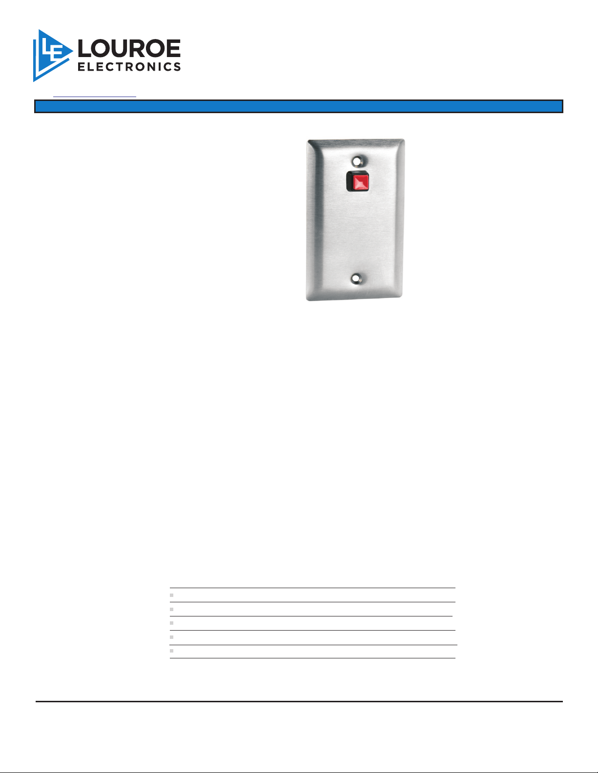
MODEL DCS
®
6955 VALJEAN AVE, VAN NUYS, CA 91406
PH: (818)994-6498 / FAX: (818)994-6458
/ www.louroe.com[email protected]
INSTALLATION AND OPERATING INSTRUCTIONS
DESCRIPTION
Model DCS is a Duress Call Station with a built-in panic button and a 3kHz oscillator mounted to the back side of a single
gang stainless steel electrical box (not supplied) for flush or surface mounting to a wall or flat surface.
REMOTE CALL STATION
When panic button is pressed, the DCS sends a 3kHz signal that alarms the Louroe sound activated base station. A
lighted LED on the base station identifies the zone in alarm. Model DCS is compatible only with the DG-12II and DG25III.
Model DCS can be connected directly to the above base stations or tied in with a Louroe Microphone (or
speaker/microphone) for providing one-way listen or two-way talk/listen with the base station.
This type of audio system can be used in applications such as:
! parking structures
! stairwells
! elevator lobbies
! elevator cabs
! secured entrances
! detention centers
SPECIFICATIONS
Tone output
Supply voltage
Dimensions
Weight 2.5 oz
Shipping Weight 1 lb
3 Vrms @ 3 kHz
12 Vdc
4 ½”x 2 3/4” W
LOUROE ELECTRONICS 6 9 5 5 VALJEAN AVENUE, VAN NUYS, CA 91406 TEL (818) 994-6498 FAX 994-6458
®
website: www.louroe.com e-mail: [email protected]
Page 1 of 4
(818)
dcs_inst_3/15
Page 2
INSTALLATION AND OPERATING INSTRUCTIONS
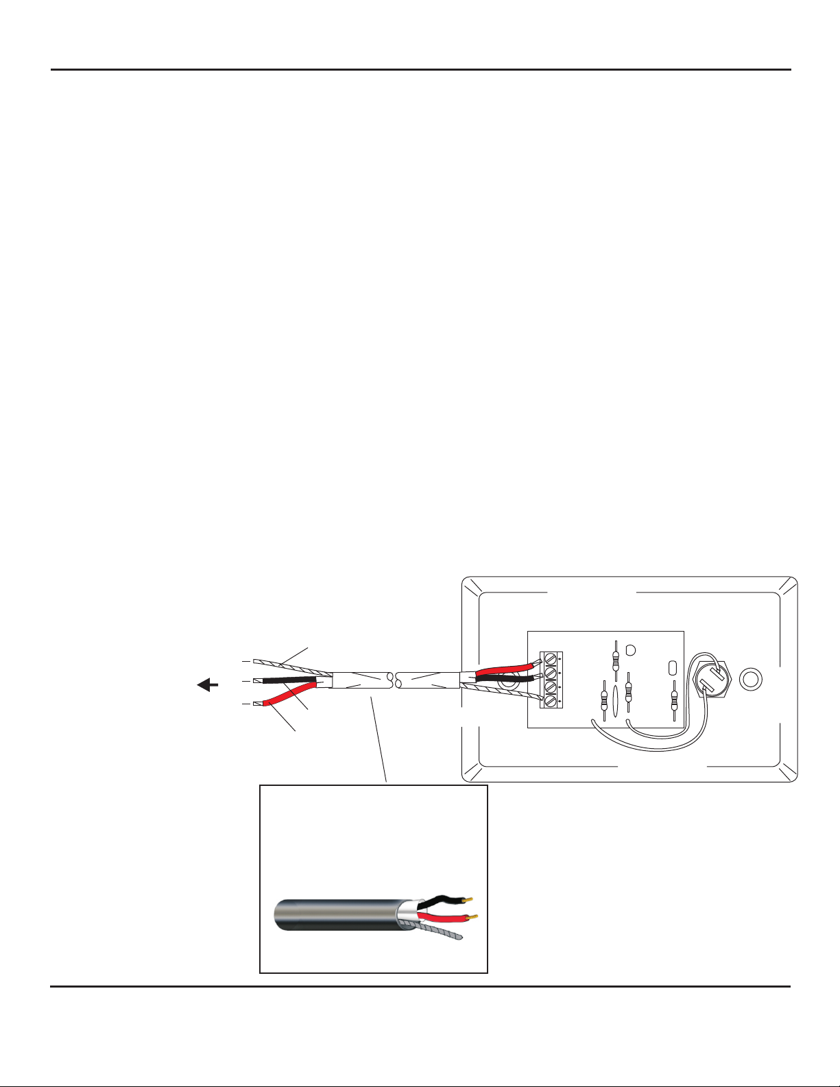
CONNECTING MODEL DCS DIRECTLY TO LOUROE BASE STATION
The PC Board of Model DCS contains a 4-pin terminal block marked 1, 2, 3, 4
1) Ground
2) Input from microphone (not used with this application)
3) Output of oscillator (3kHz)
4) 12Vdc power (positive)
NOTE: Pin #2 is used only when DCS is being connected to a Louroe Microphone
If using recommended wiring connect as follows:
BARE wire connects to Pin #1 of DCS
BLACK wire connects to Pin #3 of DCS
RED wire connects to Pin #4 of DCS
Note: Pin #2 is not used
For connecting other end of West Penn 452 to the Louroe Base Station, please refer to the specific base station
instructions for proper connection.
MODEL DCS
TO TERMINAL BLOCK OF
LOUROE DG SERIES BASE
STATION
REFER TO THE SPECIFIC BASE
STATION
INSTALLATION INSTRUCTIONS
FOR PROPER
CONNECTIONS
C
B
A
BARE
BLACK
RED RED
WIRING REQUIREMENTS
2 Conductor shielded cable, 22
gauge with a 24 gauge drain wire
NOTE: Unshielded cable is not
satisfactory for audio systems
BARE
4
3
2
1
BLACK
West Penn 452 or equivalent
LOUROE ELECTRONICS 6 9 5 5 VA L J E A N AVENUE, VAN NUYS, CA 91406 TEL (818) 994-6498 FAX 994-6458
®
website: www.louroe.com e-mail: [email protected]
Page 2 of 4
(818)
dcs_inst_3/15
Page 3
A
B
C
INSTALLATION AND OPERATING INSTRUCTIONS
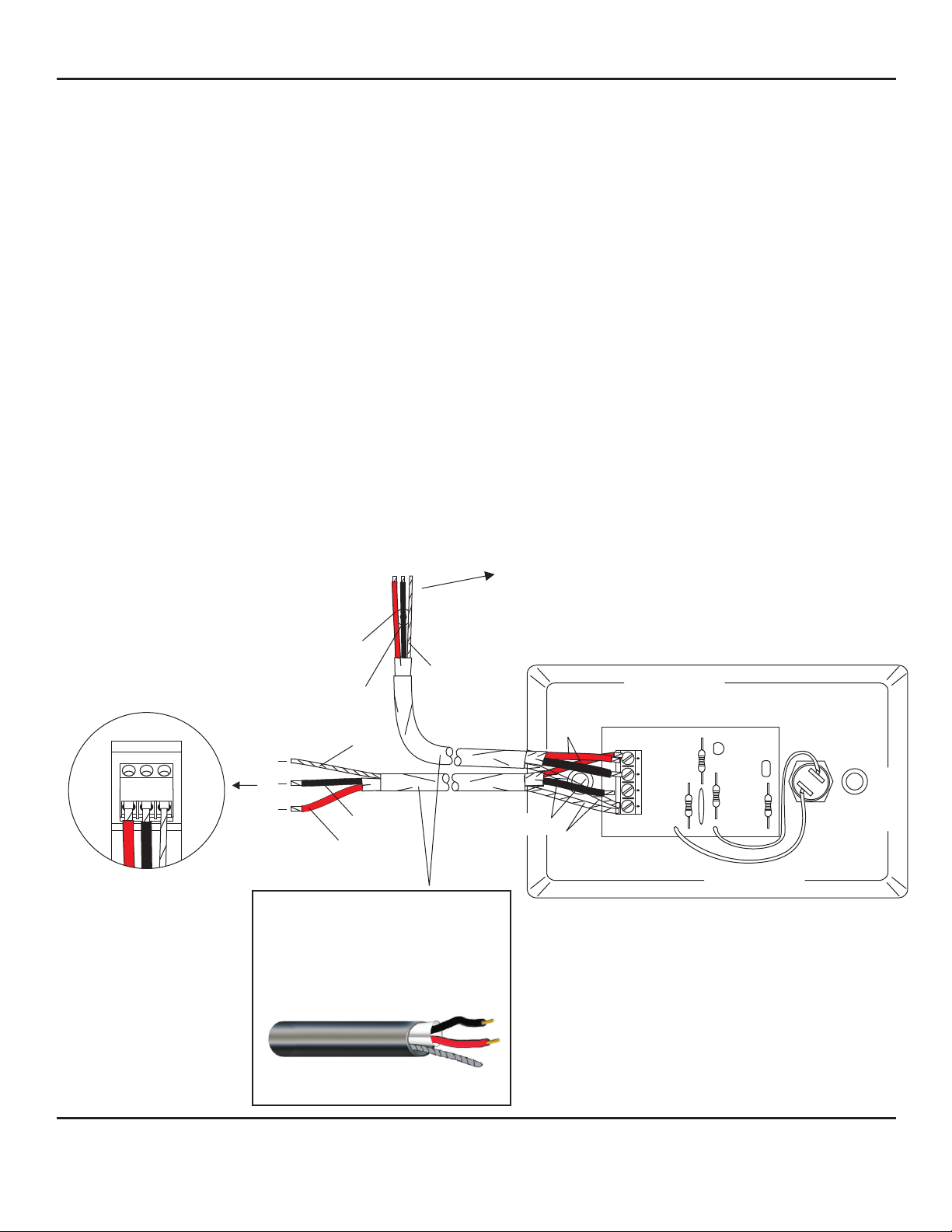
CONNECTING MODEL DCS DIRECTLY TO LOUROE MICROPHONE AND A BASE STATION
I WIRING CONNECTION TO MICROPHONE
A 3-pin terminal block is located on the back of the microphone housing, marked A, B, C
A represents +12Vdc
B represents Audio (Microphone Output)
C represents Ground
If using West Penn 452 or equivalent with same color code, connect:
Red wire (12Vdc) to terminal A of microphone terminal block
Black wire (Audio Out) to terminal B of microphone terminal block
Bare wire (Ground) to terminal C of microphone terminal block
II WIRING CONNECTION BETWEEN MICROPHONE AND DCS
Model DCS has a 4-pin terminal block on backside of face plate marked 1, 2, 3, 4
Bring other end of cable to DCS and connect as follows:
Bare wire connects to Pin 1 of DCS
Black wire connects to Pin 2 of DCS
Red wire connects to Pin 4 of DCS
III WIRING CONNECTION FROM MODEL DCS TO LOUROE SOUND ACTIVATED BASE STATION
Wiring requirements - West Penn 452 (same as used in step 1)
Bare wire connects to Pin 1 of DCS (shared with bare wire from microphone)
Black wire connects to Pin 3 of DCS
Red wire connects to Pin 4 of DCS (shared with red wire from microphone)
TO TERMINAL BLOCK OF
LOUROE DG SERIES BASE
STATION
REFER TO THE SPECIFIC BASE
STATION
INSTALLATION INSTRUCTIONS
FOR PROPER
CONNECTIONS
MODEL DCS
3-PIN BLOCK OF
LOUROE
MICROPHONE
RED
BLACK
BARE
RED
C
B
A
BARE
BLACK
RED BARE
BLACK
4
3
2
1
WIRING REQUIREMENTS
ALL LOUROE MICROPHONES
ARE COMPATIBLE
WITH MODEL DCS
2 Conductor shielded cable, 22
gauge with a 24 gauge drain wire
NOTE: Unshielded cable is not
satisfactory for audio systems
NOTE: If using wiring with a different
color code, be sure they are
West Penn 452 or equivalent
LOUROE ELECTRONICS 6 9 5 5 VA L J E A N AVENUE, VAN NUYS, CA 91406 TEL (818) 994-6498 FAX 994-6458
®
website: www.louroe.com e-mail: [email protected]
Page 3 of 4
(818)
properly matched between the
microphone and Model DCS.
dcs_inst_3/15
Page 4
INSTALLATION AND OPERATING INSTRUCTIONS
MANUFACTURED
IN THE
IMPORTANT NOTICE
When this equipment is used as part of an
audio monitoring system, the law requires
that the public be given notice of AUDIO
MONITORING ON THE PREMISES. A
deca l noti ce is includ ed with each
microphone shipped.
Federal Law References:
Federal Regulations, US Code, Title 18.
Crime and Criminal Procedure, Sec 2510.
LOUROE ELECTRONICS warrants that at the time of shipment products manufactured by LOUROE ELECTRONICS to be free of defects in material and workmanship.
Should a defect appear within one year (12 months) from date of shipment, LOUROE ELECTRONICS will, at its sole discretion, repair or replace the defective equipment.
This equipment shall not be accepted for repair or return without prior notification by LOUROE ELECTRONICS .
This warranty does not extend to any Louroe product that has been subjected to improper or incorrect installation, misuse, accident, or in violation of installation
instructions provided by LOUROE ELECTRONICS.
Returned shipments to LOUROE ELECTRONICS shall be at customer’s expense. LOUROE ELECTRONICS will return the equipment prepaid via best way.
LOUROE ELECTRONICS 6 9 5 5 VA L J E A N AVENUE, VAN NUYS, CA 91406 TEL (818) 994-6498 FAX 994-6458
®
®
®
®
WARRANTY
AUDIO
MONITORING
On
These Premises
®
®
®
®
(818)
website: www.louroe.com e-mail: [email protected]
Page 4 of 4
dcs_inst_3/15
 Loading...