

Page 1
®
6955 VALJEAN AVE, VAN NUYS, CA 91406
PH: (818)994-6498 / FAX: (818)994-6458
/ www.louroe.com[email protected]
®
ASK-4 #631
AUDIO MONITORING SYSTEM
INSTALLATION AND OPERATING INSTRUCTIONS
MODEL IF-1 INTERFACE ADAPTER
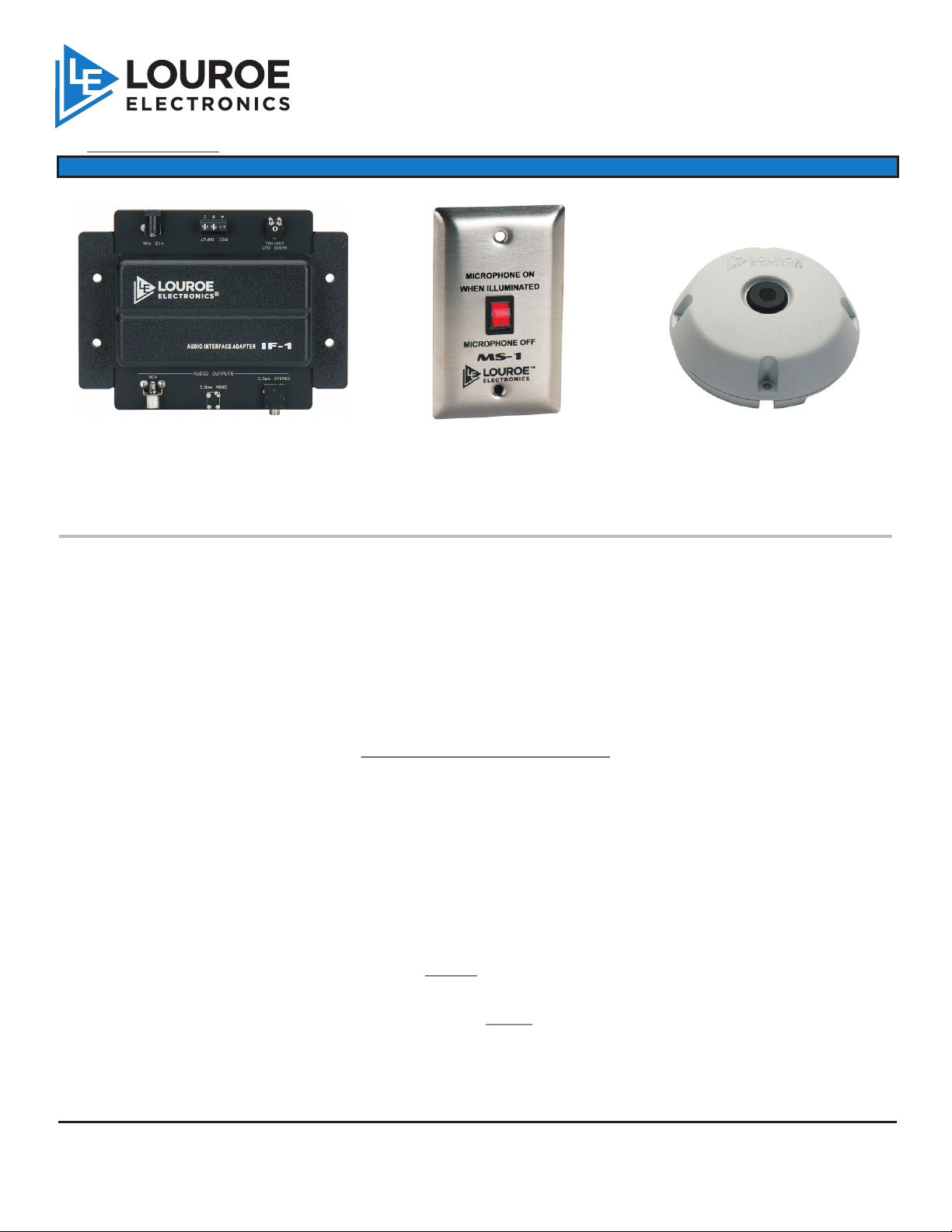
ASK-4 #631 is a single zone audio monitoring system designed for direct connection to:
®
MS-1 Mute Switch
VERIFACT A MICROPHONE
®
DVR or VCR
IP Network Camera
PC Soundcard
Video Server
or other audio receiving devices that accept line level audio
CONTENTS OF ASK-4 #631
, Verifact A Microphone Omni-directional Microphone
®
®
, Model IF-1 Audio Interface Adapter
, MS-1 Mute Switch
, Model AD-1 12 Vdc power supply
, Single RCA Cable For connection to DVR, VCR, etc.
, 3.5mm Stereo cable For connection to a Sound Card, IP
Network Camera, or Video Server with
stereo audio input
, RCA to 3.5mm Mono For connection to a IP Camera with a
Adaptor 3.5mm mono audio input
LOUROE ELECTRONICS 69 5 5 V A LJ E A N AVENUE, VAN NUYS, CA 91406 TEL (818) 994-6498 FAX 994-6458
®
website: www.louroe.com e-mail: [email protected]
Page 1 of 8
(818)
Ask4_631_inst_2/15
Page 2
INSTALLATION AND OPERATING INSTRUCTIONS
WIRING REQUIREMENTS
2 conductor shielded, 22 gauge, with a 24 gauge drain wire.
West Penn 452 or equivalent
MICROPHONE INSTALLATION - MECHANICAL
Verifact A Microphone is designed for surface mounting to a ceiling or wall. Microphone will pick up
®
sounds 15’ away from all directions. For best results, install microphone as close to desired area of
coverage as possible. Avoid mounting microphone to ceiling heights in excess of 10’, or near air
vents, refrigeration units, or other audio interferences.
NOTE: Make wiring connection on back side of microphone before installing microphone to ceiling or
flat surface.
MICROPHONE INSTALLATION - ELECTRICAL
Located on back side of microphone is a terminal block marked A, B and C.
A is 12 Vdc
B is Audio
C is Ground (common)
Using recommended wiring, connect as follows:
RED wire to terminal A (12Vdc)
BLACK wire to terminal B (Audio)
BARE wire to terminal C (Ground)
NOTE: If using wiring from other manufacturers,
color code may vary.
MS-1 MECHANICAL INSTALLATION
The MS-1 (Mute Switch) fits in a single gang electrical box for flush or surface mounting to a wall.
Electrical connection is thru a 3 Pin Terminal block.
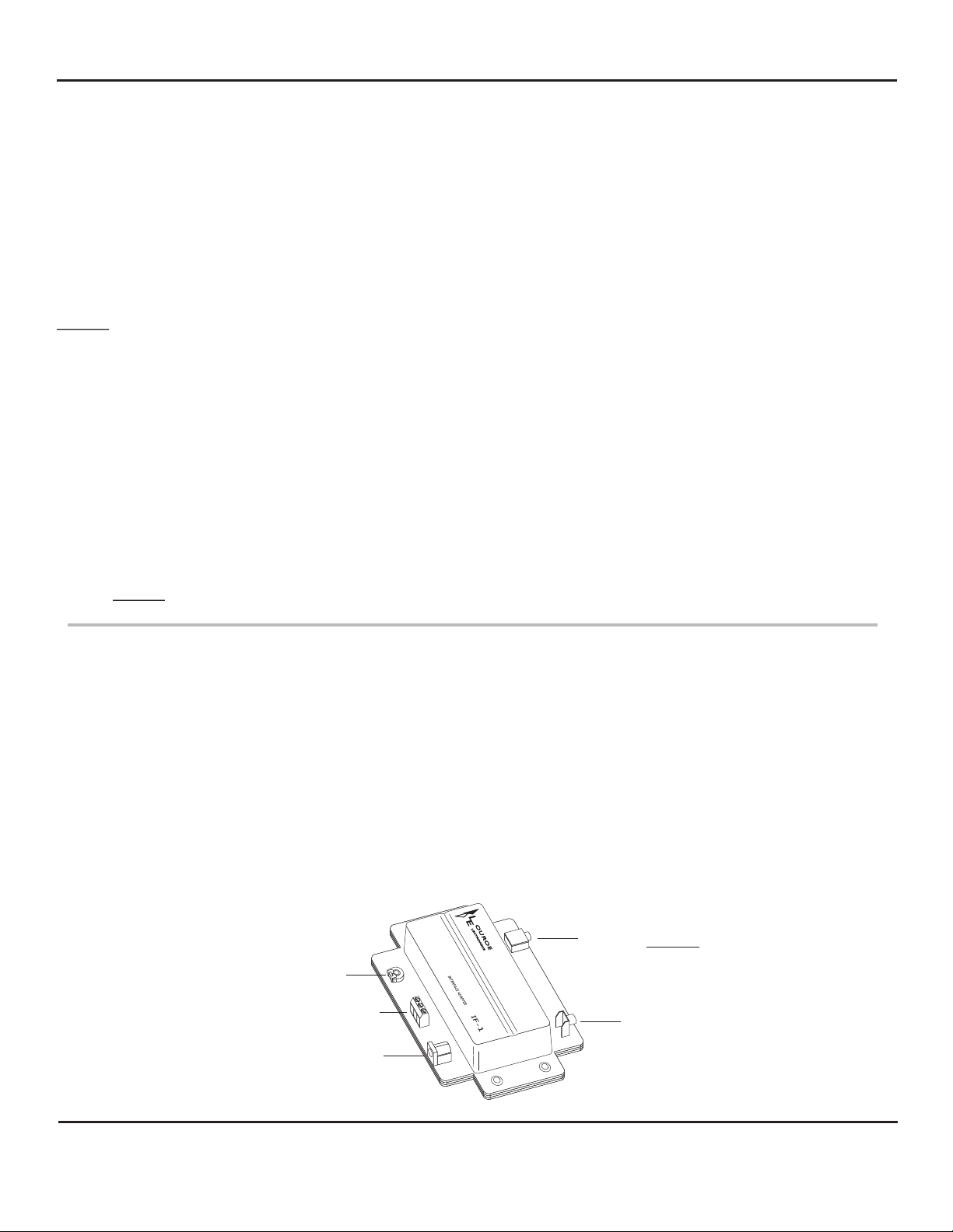
LOUROE MODEL IF-1 AUDIO INTERFACE ADAPTER
3.5mm Stereo Audio Out Jack
Audio Out Control
(Gain Adjustment)
Microphone Input Terminal Block
12 Vdc Power Jack
LOUROE ELECTRONICS 69 5 5 VA L J E A N AVENUE, VAN NUYS, CA 91406 TEL (818) 994-6498 FAX 994-6458
®
website: www.louroe.com e-mail: [email protected]
Page 2 of 8
RCA Audio Out Jack
(818)
Ask4_631_inst_2/15
Page 3

INSTALLATION AND OPERATING INSTRUCTIONS
MECHANICAL INSTALLATION - MODEL IF-1 INTERFACE ADAPTER
The IF-1 Interface Adapter serves as an interface device between the microphone and the audio receiver
(DVR/VCR, PC sound card, etc.). The IF-1 can be installed several ways:
1) Wall mounted close to DVR/VCR or IP Network Camera, etc.
2) Attached to side of the receiving device using two-way ¼” adhesive tape
(not provided)
MICROPHONE CONNECTION TO IF-1 INTERFACE ADAPTER VIA THE MS-1 (See
interconnection diagram on the next page)
Connect 2 cond shielded cable to the microphone terminal block as follows:
a. Using recommended cable, connect black wire to terminal B of microphone.
b. Connect bare (ground) wire to terminal C.
c. Connect red wire directly to terminal A of the MS-1 using a wire nut from a second 2 cond cable.
d. Connect the other end of this cable to IF-1 (red to terminal A; black to terminal B; and bare to
terminal C)
Using the second 2 cond shielded cable;
a. Connect red wire to terminal A of the MS-1 (the other end of this wire is connected to the first 2
cond cable mentioned above on “c”)
b. Connect black wire between terminal B of MS-1 and terminal A of microphone.
c. Connect both ends of bare wire to terminals C of microphone and MS-1
To apply power to the system, Model AD-1 12Vdc power supply is included. First connect small end (female
90° plug) into 12Vdc jack on IF-1, then connect 2-prong power block to a standard 110Vac outlet
or power strip.
NOTE: Model IF-1 contains two types of audio outputs. A connection cable is provided for each type.
1) RCA
2) 3.5mm stereo
3) RCA to 3.5mm mono with adaptor
These two audio outputs are in parallel ... only one can be used
CONNECTION BETWEEN IF-1 INTERFACE ADAPTER AND DVR/VCR WITH RCA TYPE AUDIO
CONNECTIONS
To make connection to DVR/VCR, plug the RCA cable (supplied) into the RCA type audio output jack located
on the output side of Model IF-1. Connect other end of RCA cable to the DVR/VCR’s “AUDIO IN” jack.
CONNECTION BETWEEN IF-1 AND AN IP NETWORK CAMERA, DVR, VIDEO SERVER WITH
3.5mm MONO TYPE AUDIO CONNECTIONS
To make connection to IP Network Camera, plug the RCA to 3.5mm mono cable with adaptor (supplied) into
the RCA audio out jack located on the output side of IF-1, connect other end of cable (3.5mm) to the camera’s
audio in jack.
CONNECTION BETWEEN IF-1 AND A DVR, IP NETWORK CAMERA OR PC SOUNDCARD WITH
3.5mm STEREO TYPE CONNECTION.
To make connection, plug the 3.5mm stereo cable (supplied) into the “audio out” jack located on the output
side of IF-1. Plug the other end of the cable to “AUDIO IN” of DVR, IP Network Camera or “ LINE IN” of PC
soundcard.
LOUROE ELECTRONICS 69 5 5 VA L J E A N AVENUE, VAN NUYS, CA 91406 TEL (818) 994-6498 FAX 994-6458
®
website: www.louroe.com e-mail: [email protected]
Page 3 of 8
(818)
Ask4_631_inst_2/15
Page 4

INSTALLATION AND OPERATING INSTRUCTIONS
OPERATION
With the addition of the MS-1 (Mute Switch), the microphone audio can be muted if not needed. Turn On the
rocker switch on the MS-1 to activated the audio of the microphone. The built-in red light on the switch will light
indicating that the microphone is live and audio is present at the IF-1. If the output of the IF-1 is connected to a
receiver such as a DVR, Video Encoder or IP Camera, audio is present on the input of these receivers.
Turning OFF the MS-1, will turn OFF the audio from the microphone and the built-in light on the switch is not
lighted.
SENSITIVITY SWITCH OF MICROPHONE
For special installations that require less microphone sensitivity, a sensitivity switch has been added
to the microphone pre-amp (PC board) and has two positions - N and L:
N represents normal sensitivity (0dB output into 600W)
L represents low sensitivity (-6dB output into 600W)
NOTE: Louroe™ Verifact microphones are always shipped with the sensitivity switch in
normal (N) position. Do not change unless required.
To make an adjustment, use a small screwdriver and move slide switch from N to L. Sensitivity
switch is located on the backside of Verifact™ A Microphone.
LOUROE ELECTRONICS 69 5 5 VA L J E A N AVENUE, VAN NUYS, CA 91406 TEL (818) 994-6498 FAX 994-6458
®
website: www.louroe.com e-mail: [email protected]
Page 4 of 8
(818)
Ask4_631_inst_2/15
Page 5
INSTALLATION AND OPERATING INSTRUCTIONS
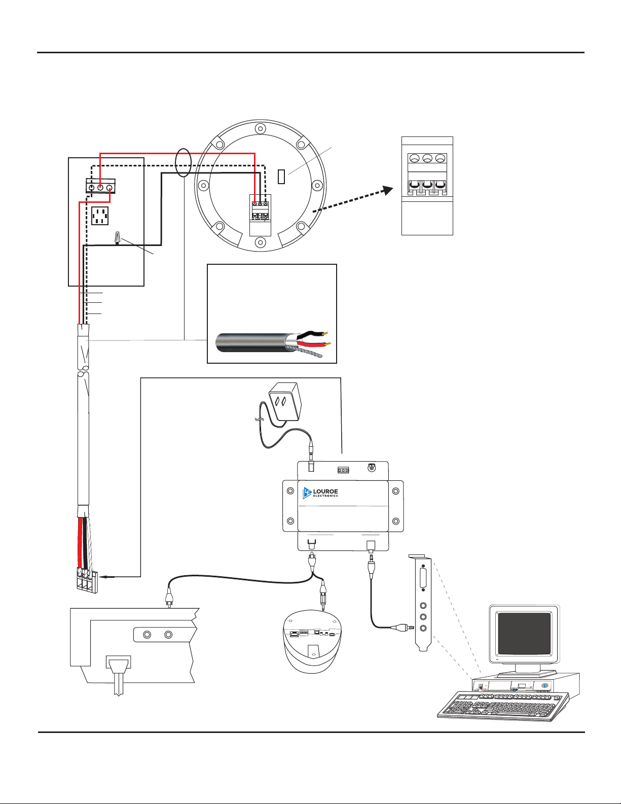
INTERCONNECTION DIAGRAM
FOR
LOUROE ASK-4 #631 AUDIO MONITORING SYSTEM AND DVR/VCR, VIDEO
SERVER, IP CAMERA ETC. WITH DIFFERENT AUDIO INPUT
A B C
Gain adjust switch
(factory set)
B
C
MS-1
Mute Switch
RED
BLACK
BARE
A
WIRE NUT
N
L
A B C
MODEL VERIFACT A
Terminal block
of Verifact A
®
WIRING REQUIREMENTS
2 Conductor shielded
cable, 22 gauge with a 24
gauge drain wire
®
West Penn 452 or equiv
Model AD-1
+12 Vdc
POWER
SUPPLY
C
A B
+12 Vdc
MIC INPUT
CONTROL
AUDIO OUT
MODEL IF-1
Interface Adapter
Terminal block
A
B
of IF-1
C
OUT IN
OR
REAR PANEL OF
RECORDING DEVICE
LOUROE ELECTRONICS 69 5 5 VA L J E A N AVENUE, VAN NUYS, CA 91406 TEL (818) 994-6498 FAX 994-6458
®
IP NETWORK CAMERA
IF-1
RCA
AUDIO OUTPUTS
3.5mm STEREO
SPKR
MIC
LINE
OR
(818)
PC SOUND CARD
website: www.louroe.com e-mail: [email protected]
Page 5 of 8
Ask4_631_inst_2/15
Page 6

INSTALLATION AND OPERATING INSTRUCTIONS
SPECIFICATIONS (MS-1 Mute Switch)
Supply Voltage
Dimensions
Faceplate
Backbox
Weight
SPECIFICATIONS (IF-1 Interface Adapter)
Input impedance
Output impedancel
Power supply
Dimensions
Audio output gain
Weight
12Vdc
2 ¾ W x " 4 ½" H
303 Stainless Steel
Single gang electrical
box (not included)
2.5 oz
17.5 KW @ 1kHz
600W @1kHz
12Vdc, 500 mA
6 1/8”L x 4 5/8”W x 1 3/8”H
up to +10dB
5.5 oz
SPECIFICATIONS (Microphone - Model A)
Type
Output
Frequency response
Current drain
Supply voltage
Dimensions
Weight
Shipping Weight of kit
Electret Condenser
Line Level (0 dB 600W @ 1 kHZ)
50 Hz to 15 kHz ± 1 dB
10 mA
12Vdc
4"Dia x 1 ½"H
3.5 oz
2 lbs
LOUROE ELECTRONICS 69 5 5 VA L J E A N AVENUE, VAN NUYS, CA 91406 TEL (818) 994-6498 FAX 994-6458
®
website: www.louroe.com e-mail: [email protected]
Page 6 of 8
(818)
Ask4_631_inst_2/15
Page 7

INSTALLATION AND OPERATING INSTRUCTIONS
MANUFACTURED
IN THE
When this equipment is used as part of an audio monitoring
system, the law requires that the public be given notice of
AUDIO MONITORING ON THE PREMISES. A decal notice is
included with each microphone shipped.
Federal Law References:
Federal Regulations, US Code, Title 18. Crime and Criminal
LOUROE ELECTRONICS warrants that at the time of shipment products manufactured by LOUROE ELECTRONICS to be free of defects in material and workmanship.
Should a defect appear within one year (12 months) from date of shipment, LOUROE ELECTRONICS will, at its sole discretion, repair or replace the defective equipment.
This equipment shall not be accepted for repair or return without prior notification by LOUROE ELECTRONICS .
This warranty does not extend to any Louroe product that has been subjected to improper or incorrect installation, misuse, accident, or in violation of installation
instructions provided by LOUROE ELECTRONICS.
Returned shipments to LOUROE ELECTRONICS shall be at customer’s expense. LOUROE ELECTRONICS will return the equipment prepaid via best way.
LOUROE ELECTRONICS 69 5 5 VA L J E A N AVENUE, VAN NUYS, CA 91406 TEL (818) 994-6498 FAX 994-6458
®
®
®
®
IMPORTANT NOTICE
WARRANTY
AUDIO
MONITORING
On
These Premises
®
®
®
®
(818)
website: www.louroe.com e-mail: [email protected]
Page 7 of 8
Ask4_631_inst_2/15
Page 8

LOUROE ELECTRONICS 69 5 5 VA L J E A N AVENUE, VAN NUYS, CA 91406 TEL (818) 994-6498 FAX 994-6458
®
(818)
website: www.louroe.com e-mail: [email protected]
Page 8 of 8
Ask4_631_inst_2/15
 Loading...