

Page 1
6955 VALJEAN AVE, VAN NUYS, CA 91406
PH: (818)994-6498 / FAX: (818)994-6458
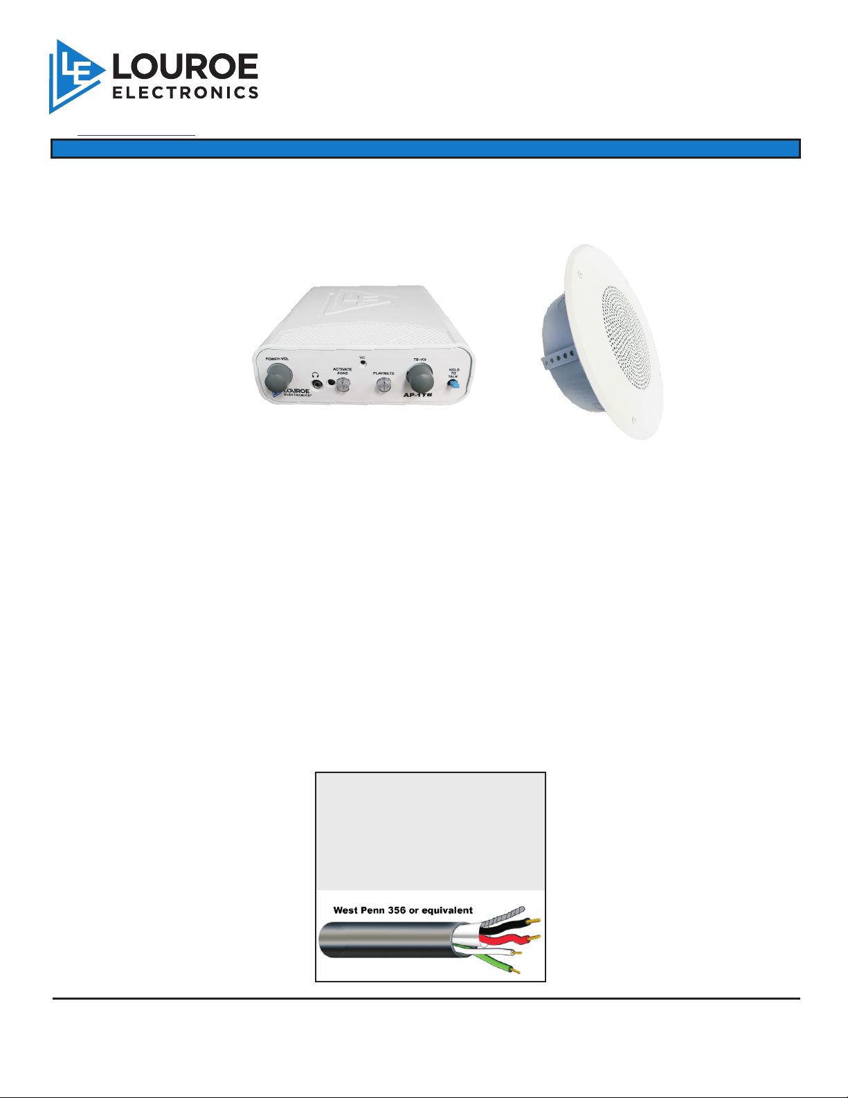
FIG. 1 ASK-4® 501-TLM-CF
/ www.louroe.com[email protected]
ASK-4
®
INSTALLATION AND OPERATING INSTRUCTIONS
AP-1 TB Audio Base Station
®
#501-TLM-CF
AUDIO MONITORING SYSTEM
MODEL TLM-CF
Speaker/Microphone
Wall mount
INTRODUCTION
The ASK-4® 501-TLM-CF is a single zone audio monitoring system with 2-way talk/listen capabilities. It consists of a
remote speaker/microphone and audio base station with built-in microphone and speaker.
DESCRIPTION OF EQUIPMENT
AP-1TB
AUDIO BASE STATION
MODEL TLM-CF
AC ADAPTER
DUAL RCA CONNECTOR
CABLE (not shown)
(Not shown)
A single zone desk top audio base station. Contains a built-in microphone and speaker for
listen and talkback with the remote unit (Model TLM-CF). Has input/output to DVR/VCR for
live audio and playback. UL listed.
Two-way speaker/microphone - contains an electret condenser microphone and a 3” speaker.
Included is a plastic backbox for surface mounting to a wall or flat surface.
UL® listed power supply. Supplies 12 Vdc, 500mA to both AP-1TB and TLM-CF.
For output/input connection to a DVR/VCR for audio recording and playback.
WIRING REQUIREMENTS
+
4 Conductor consisting of:
+
2 Conductor shielded, 20 gauge
with 22 gauge drain (microphone
connection)
+
2 Conductor unshielded, 18 gauge
(speaker connection)
All in the same jacket
LOUROE ELECTRONICS 6 9 5 5 VALJEAN AVENUE, VAN NUYS, CA 91406 TEL (818) 994-6498 FAX 994-6458
®
website: www.louroe.com e-mail: [email protected]
Page 1 of 8
(818)
Ask4_501-TLM-CF_inst_12/11
Page 2
DESCRIPTION OF PARTS
INSTALLATION AND OPERATING INSTRUCTIONS
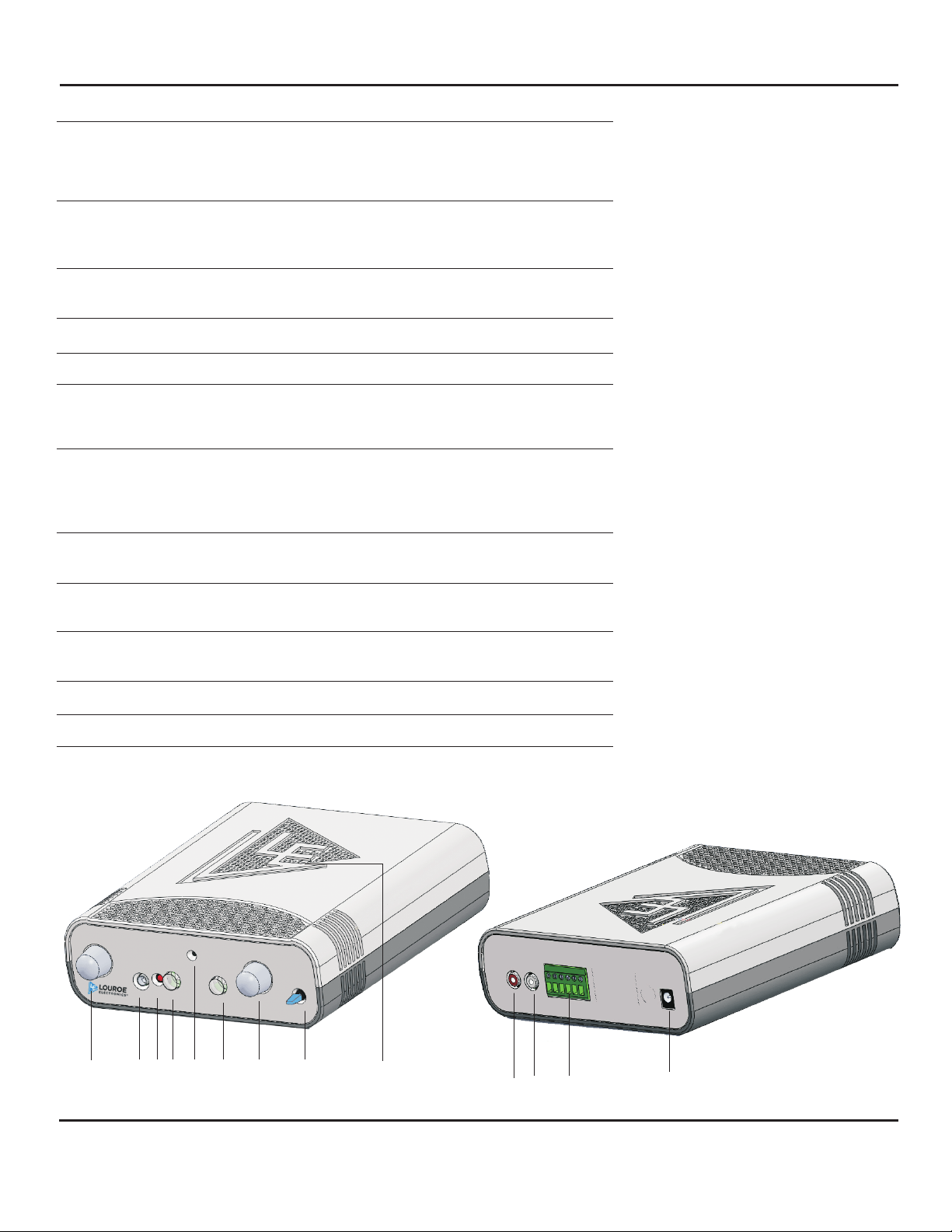
[1] Power-Volume
Control
Turns ON power to the unit as indicated by the
Power LED[3]. Turning the knob more clockwise
increase the volume of the monitored audio heard at
the Speaker[9]
[2] Headphone Jack Used for private listening. Any 3.5mm stereo
headphone with 8? to 600? impedance may be
used. Mutes AP-1TB speaker output when in use.
[3] Power LED Lights when Power-Volume Control[1] is turned ON
indicating power to the unit.
[4] Zone Switch Press to activate two-way audio monitoring.
[5] Talkback MIC Built-in microphone for talkback.
[6] Playback/Mute
Switch
Used when playing back audio from a recorder or
mute the audio from the microphone. No audio is
heard on the Speaker[9] when this switch is ON.
[7] Talkback Volume
Control
Rotate clockwise to increase the loudness of audio
heard at the remote Speaker/MIc unit. Rotate
counterclockwise to decrease the level of audio
heard at the remote Speaker/Mic.
[8] Talkback Switch Hold down and talk so audio can be heard at the
remote Speaker/Mic unit.
[9] Monitor Speaker Monitored audio is heard at this speaker. Muted
when a headset is plug into Headphone Jack[2]
[10] Audio-In Jack Receives audio from an external source (recorded
playback from a DVR or VCR).
[11] Audio-OUT Jack Sends audio to an external receiver (DVR, VCR, etc.)
[12] MIC 6-Pin Terminal Connects to speaker/microphone at remote location.
[13] DC-IN Jack Accepts 12 Vdc from external power supply (AC
Adapter included).
Fig. 2
AUDIO
AUDIO
A
B C S
P
OUT
G P
IN
+12Vddc
500mA
1
LOUROE ELECTRONICS 6 9 5 5 VALJEAN AVENUE, VAN NUYS, CA 91406 TEL (818) 994-6498 FAX 994-6458
2
3 4 5
7 8 9
6
®
®
10
11 12
13
(818)
website: www.louroe.com e-mail: [email protected]
Page 2 of 8
Ask4_501-TLM-CF_inst_12/11
Page 3
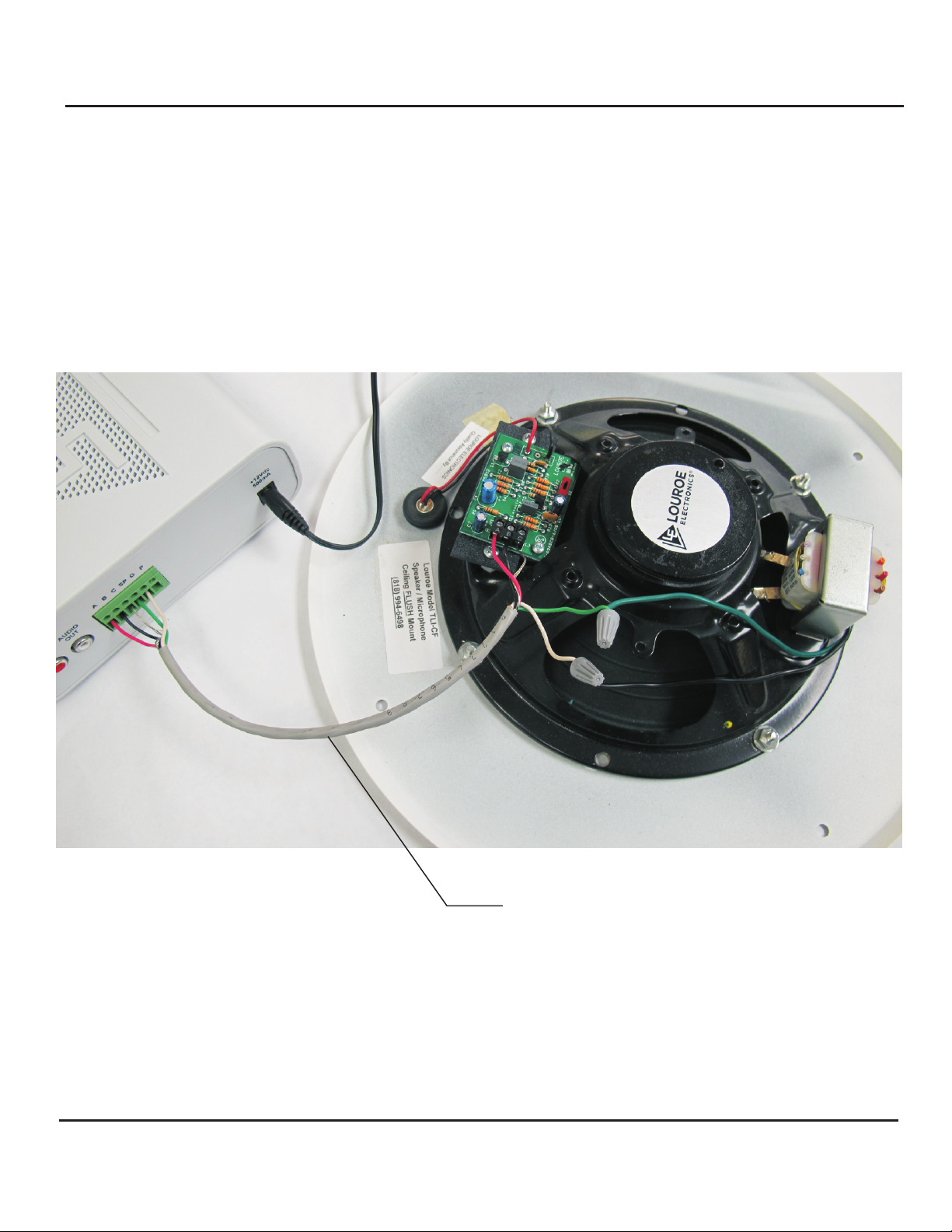
Fig. 3
INSTALLATION AND OPERATING INSTRUCTIONS
INTERCONNECTION DIAGRAM
FOR
MODEL TLI-CF SPEAKER/MICROPHONE
AND AP-1TB BASE STATION
4 Cond Shielded Cable consisting of:
2 Cond Shielded #20 AWG with Drain Wire (Microphone)
2 Cond Unshielded #18 AWG (Speaker)
LOUROE ELECTRONICS 6 9 5 5 VA L J E A N AVENUE, VAN NUYS, CA 91406 TEL (818) 994-6498 FAX 994-6458
®
website: www.louroe.com e-mail: [email protected]
Page 3 of 8
(818)
Ask4_501-TLM-CF_inst_12/11
Page 4

INSTALLATION AND OPERATING INSTRUCTIONS
INSTALLATION OF TLM-CF SPEAKER/MICROPHONE
Model TLM-CF is designed for mounting to a wall or flat surface. Included is a plastic backbox for surface mounting to a
wall. If flush mounting is needed, a 3 gang electrical box (not supplied) maybe used.
1) Drill an opening at top, bottom, side or back of backbox for passing wiring or connecting conduit.
Four small screws are supplied for attaching backbox to a wall.
2) Four screws are also supplied for attaching the TLM faceplate to the backbox. The plastic hole plugs must be place on
the screw holes of the faceplate to cover the screws.
WIRING CONNECTIONS BETWEEN MODEL TLM-CF SPEAKER/MICROPHONE AND AP-1TB
AUDIO BASE STATION
1) Connect one end of recommended cable to remote speaker/microphone (TLM-CF) as shown in Fig. 4. Connect wires
wrapped with overall shield to terminals “A”, “B”, and “C” of TLM-CF’s terminal block. When using sample cable,
connect red wire to terminal “A”; black wire to terminal “B” and bare wire to terminal “C”.
2) Connect the two speaker wires (twisted pair) green and white to green and white wires of TLM-CF’s 70V transformer.
Using wire nut connect green wire to green wire of TLM-CF’s 70V Transformer. Again, using wire nut connect white
wire to white wire of TLM-CF’s 70V Transformer.
3) Connect the other end of the cable to AP-1TB Mic 6-Pin Terminal Block [12]. Make sure that wire connected to
terminal “A” of remote TLM-CF connects to terminal “A” of AP-1TB’s Mic 6-Pin Terminal Block [12]; wire connected to
terminal “B” of TLM-CF connects to terminal “B” of AP-1TB; “C” to “C”. Observe cable color coding. Terminal “P” of
AP-1TB is not used with this application. Used only when paralleling to a second AP-1TB.
4) For speaker connection, connect green speaker wire (positive) to Mic 6-Pin Terminal Block [12] terminal “SP”,
connect white speaker wire (ground) to “G”.
5) When a recording device is used (DVR,VCR,etc.) connect Audio-OUT Jack [11] to recorder’s Audio-IN Jack with the
dual RCA cable (supplied).
6) Connect Audio-IN Jack [10] to recorder’s Audio-OUT Jack with the remaining RCA plug.
LOUROE ELECTRONICS 6 9 5 5 VA L J E A N AVENUE, VAN NUYS, CA 91406 TEL (818) 994-6498 FAX 994-6458
®
website: www.louroe.com e-mail: [email protected]
Page 5 of 8
(818)
Ask4_501-TLM-CF_inst_12/11
Page 5

INSTALLATION AND OPERATING INSTRUCTIONS
OPERATION AND TEST
1) Applying Power To The System
With all wiring connections complete, power up the system using the 12Vdc, 500mA power supply included with the kit.
First connect the small end of power supply to the DC IN Jack [13] located on rear panel of AP-1TB Base Station.
Connect the large end with the 2-prong plug to a standard 120Vac wall outlet or power strip.
2) Rotate the Power-Volume Control[1] ON position as indicated by the Power LED[3] Power LED [3] will illuminate.
3) Testing For Listen And Talkback At The AP-1TB Base Station Listen Mode
Push in Zone Switch [4] located on front panel of AP-1TB. Zone Switch[4] will illuminate (blue) and two-way
communication is now activated. Have someone create sound by talking at the remote Model TLM-CF
Speaker/Microphone. Audio should be present via the AP-1TB’s Monitor Speaker [9]. Adjust loudness of sound heard
at the Monitor Speaker[9] by rotating the Power-Volume Control[1] clockwise to increase or counterclockwise to
decrease.
4) Talkback Mode
To speak out to the remote TLM-CF, press and hold down Talkback Switch [8] of the AP-1TB. Another person is
needed to listen at the TLM-CF location. If talkback volume needs adjusting, rotate Talkback Volume Control[7]
clockwise to increase or counterclockwise to decrease.
5) Audio Recording And Playback
Model AP-1TB contains an Audio Out Jack [11] and an Audio In Jack [10], located on rear panel. Included with kit is
a color coded dual RCA connector cable. RCA plugs are usually red and gray.
For recording, take one end of dual RCA cable (red) and connect to Audio Out Jack [11] of AP-1TB. Connect other
end (same color) to Audio In of the recording device (DVR, VCR, etc.). For listening to recorded playback through the
AP-1TB, connect RCA plug into Audio Out of the recording device and the other end of RCA plug to Audio-In Jack [10]
of AP-1TB. Push in Playback/MuteSwitch [6] to activate playback mode. Playback/Mute Switch[6] will illuminate
(orange).The unit is now ready to receive audio from the recorder. Press playback on the recorder. Recorded audio can
now be heard at the AP-1TB Monitor Speaker[9].This switch must be turn OFF if not being use for playback as the
same switch can be used for muting the audio heard at the Monitor Speaker[9] when monitoring audio.
This switch can be used either for muting the sound of the remote microphone heard on the unit’s speaker or listening
for playback audio from a recorder.
LOUROE ELECTRONICS 6 9 5 5 VA L J E A N AVENUE, VAN NUYS, CA 91406 TEL (818) 994-6498 FAX 994-6458
®
website: www.louroe.com e-mail: [email protected]
Page 6 of 8
(818)
Ask4_501-TLM-CF_inst_12/11
Page 6

INSTALLATION AND OPERATING INSTRUCTIONS
SPECIFICATIONS (Speaker/Mic - Model TLM-CF)
SPECIFICATIONS (Microphone)
Type:
Output line level (0 dB @ 1000W)
Output impedance (mic only)
Frequency response
Current drain
Supply voltage
SPECIFICATIONS (Speaker)
Power rating
Input
Frequency response
Voice coil impedance
Speaker size
Weight, net (incl. mounting assy)4”2 Lbs (0.9 Kg)
Model BR-4 Grill for TLM-CF
Model ERD-4 Backbox for TLM-CF
Electret Condenser
600 unbalanced
40 Hz to 15 kHz ± 1 dB
4 mA
12 Vdc
10W
70.7V constant
150 Hz to 12 kHz
8
7 5/8” Dia
7¼ ” Dia x 3¼” H
SPECIFICATIONS (Base Station - AP-1TB)
Input sensitivity
(from remote microphone)
Input sensitivity
(talkback microphone)
Monitor power output 1W @ 8W
Talkback power output
Audio line output impedance
Audio input impedance
Audio frequency response
Headphone impedance
Power input 12 Vdc, 500mA
Dimensions
Weight
0.78Vrms
-45 dB
1W into 70V Line
600W
10kW
100 Hz to 10kHz
8W to 600W
7.9”L x 6.6”W x 2.4”H
2.2 lbs (1kg)
NOTE
Model AP-1TB Audio Base Station of ASK-4 Kit #501-TLMCF is supplied with a 70V talkback output, which is
standard for most audio applications. Should a 600Ù
talkback output be required, please contact our factory for
details regarding instructions for switching over to 600Ù.
Louroe Electronics®
LOUROE ELECTRONICS 6 9 5 5 VA L J E A N AVENUE, VAN NUYS, CA 91406 TEL (818) 994-6498 FAX 994-6458
®
website: www.louroe.com e-mail: [email protected]
Page 7 of 8
(818)
Ask4_501-TLM-CF_inst_12/11
Page 7

MANUFACTURED
IN THE
IMPORTANT NOTICE
When this equipment is used as part of an
audio monitoring system, the law requires
that the public be given notice of AUDIO
MONITORING ON THE PREMISES. A
decal notice is included with each
microphone shipped.
Federal Law References:
Federal Regulations, US Code, Title 18.
Crime and Criminal Procedure, Sec 2510.
LOUROE ELECTRONICS warrants that at the time of shipment products manufactured by LOUROE ELECTRONICS to be free of defects in material and workmanship.
Should a defect appear within one year (12 months) from date of shipment, LOUROE ELECTRONICS will, at its sole discretion, repair or replace the defective equipment.
This equipment shall not be accepted for repair or return without prior notification by LOUROE ELECTRONICS .
This warranty does not extend to any Louroe product that has been subjected to improper or incorrect installation, misuse, accident, or in violation of installation
instructions provided by LOUROE ELECTRONICS.
Returned shipments to LOUROE ELECTRONICS shall be at customer’s expense. LOUROE ELECTRONICS will return the equipment prepaid via best way.
LOUROE ELECTRONICS 6 9 5 5 VA L J E A N AVENUE, VAN NUYS, CA 91406 TEL (818) 994-6498 FAX 994-6458
®
®
®
®
WARRANTY
AUDIO
MONITORING
On
These Premises
®
®
®
®
(818)
website: www.louroe.com e-mail: [email protected]
Page 8 of 8
Ask4_501-TLM-CF_inst_12/11
 Loading...