

Page 1
®
6955 VALJEAN AVE, VAN NUYS, CA 91406
PH: (818)994-6498 / FAX: (818)994-6458
/ www.louroe.com[email protected]
®
ASK-4
#401
AUDIO MONITORING SYSTEM
INSTALLATION AND OPERATING INSTRUCTIONS
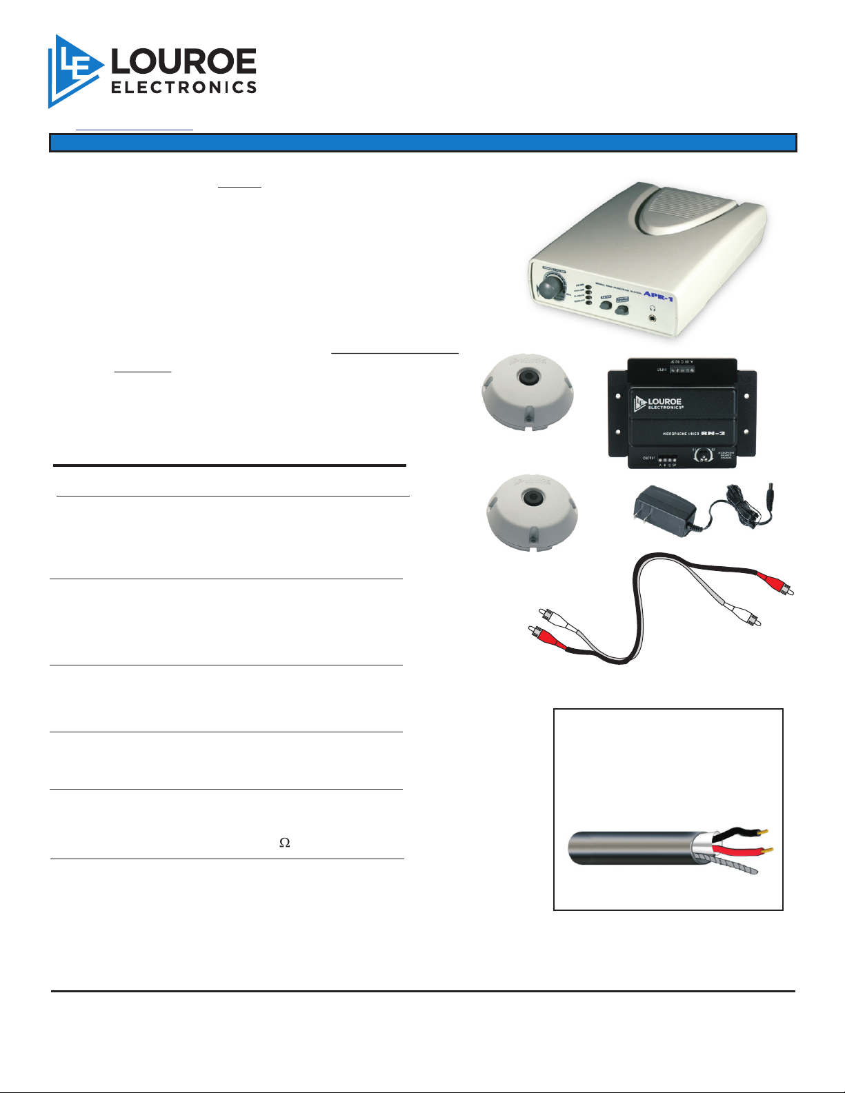
The ASK-4 #401 is a single zone audio monitoring
®
system with two Verifact A Microphones that work
together for extended zone coverage. Model APR-1
Base Station contains a 3” speaker for both live audio
and audio playback. The system is designed to
interface with a DVR, VCR or other audio devices that
accepts line level input.
NOTE: The two microphones are designed to expand
the area of coverage and are NOT SEPARATE
ZONES. Both microphones serve as one
audio zone with approximate coverage of 30’ x
60’ in a normal acoustical environment.
Contents Description
APR-1 Audio Base Station. Used for
listening to live audio produced
from the microphone, as well as
audio playback from DVR, VCR
or other external sources.
Verifact A Microphone Electret condenser microphone
®
with preamp. Picks up normal
sounds within 30’ circle. May be
located up to 1000’ from APR-1
Base Station.
APR-1 Base Station
VERIFACT A
VERIFACT A
®
®
RN-2
AD-1
DUAL RCA Cable
RN-2 Microphone Mixer Microphone mixer for combining
two microphones in a zone.
Contains a control for microphone
balance.
AD-1 UL® approved AC ADAPTER.
Supplies 12 Vdc to APR-1, RN2
and Microphone.
Dual RCA Cable RCA cable for connections to a
DVR/VCR or other audio sources
that accept line level audio input
(0dB @ 600 ).
LOUROE ELECTRONICS 6 9 5 5 VALJEAN AVENUE, VAN NUYS, CA 91406 TEL (818) 994-6498 FAX 994-6458
®
website: www.louroe.com e-mail: [email protected]
Page 1 of 8
WIRING REQUIREMENTS
2 Conductor shielded cable, 22
gauge with a 24 gauge drain wire
NOTE: Unshielded cable is not
satisfactory for audio systems
West Penn 452 or equivalent
(818)
Ask4_401_inst_2/15
Page 2
INSTALLATION AND OPERATING INSTRUCTIONS
DESCRIPTION
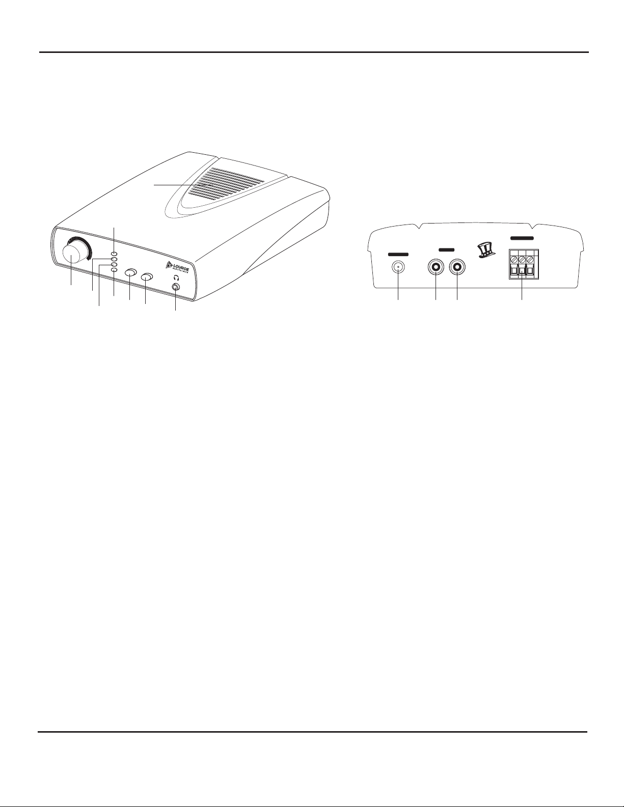
THE APR-1 IS SHOWN BELOW. ALL CONTROLS ARE LOCATED AT THE FRONT PANEL. ALL CONNECTIONS ARE
MADE AT THE REAR PANEL.
FRONT PANEL LAYOUT OF APR-1
[9]
REAR
[3]
[2]
MIC INPUT
PWR
APR-1
MUTE
MAX
PLAYBACK
MUTE
SINGLE ZONE
[6]
PUSH FOR
PLAYBACK
AUDIO
BASE
STATION
[7]
TM
[8]
OVERLOAD
[5]
[4]
+12 Vdc INPUT OUTPUT
[10] [11] [12] [13]
AUDIO
I
M
E
A
D
BA C
A
S
U
N
VAN NUYS, CA
POWER-VOLUME
OFF
[1]
[1] Power-Volume Turns “ON” power to the unit and controls the audio volume
through the Speaker[9].
[2] Power Indicator Lights (green) when the power is present to the unit.
[3] Mute Indicator Lights (orange) when Mute Switch[6] is pushed in. Audio is muted.
[4] Playback Indicator Lights (yellow) when Push for Playback[7] is pushed in to “ON” position.
[5] Overload Indicator Flashes (red) when there is a short in the power supply.
[6] Mute Switch Used to mute the audio on both live and playback mode.
[7] Push for playback Used for DVR/VCR playback. May also be used to listen to audio from an
external source. Press switch to listen to playback. Switch must be “OUT”
or “OFF” when monitoring and recording, otherwise live audio is muted.
[8] Headphone Jack Used for private listening. Any 3.5mm stereo headphone with 8W to
600W impedance can be used.
[9] Speaker (3”) Provides live audio. Muted when a headphone is connected to
Headphone Jack [8].
[10] Power Jack Connects to 12Vdc power supply
[11] AUDIO-IN Jack (RCA) Accepts audio playback from DVR/VCR, etc. Audio is produced through the speaker.
The Push for Playback Switch [7] must be IN during audiolayback.
[12] AUDIO-OUT Jack (RCA) Provides audio output and connection to a DVR, VCR, etc.
[13] Audio Terminal Block A 3-pin terminal block marked A, B and C.
Accepts wiring from remote Verifact™ A Microphone.
A = +12Vdc Power (red wire)
B = Audio (black wire)
C = Ground (bare wire)
LOUROE ELECTRONICS 6 9 5 5 VALJEAN AVENUE, VAN NUYS, CA 91406 TEL (818) 994-6498 FAX 994-6458
®
(818)
website: www.louroe.com e-mail: [email protected]
Page 2 of 8
Ask4_401_inst_2/15
Page 3

INSTALLATION AND OPERATING INSTRUCTIONS
MICROPHONE CONNECTIONS
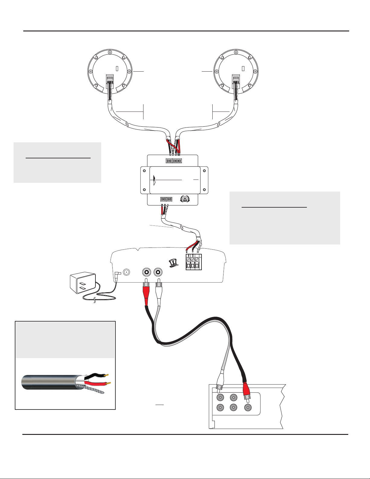
The color code for recommended wire is red, black and a bare wire. On the backside of Verifact A Microphone is a 3-pin
®
terminal block marked A, B, C. Connect as follows:
Red wire goes to terminal A (12 Vdc Power)
Black wire goes to terminal B (Audio Out)
Bare wire goes to terminal C (ground)
Use the same procedure for the second Verifact™ A Microphone.
CONNECTION TO RN-2 MICROPHONE MIXER
The RN-2 Mixer has an input side and output side.
Bring wire from microphone #1 to the input side and connect as follows:
Wire from terminal A of microphone #1 goes to terminal A
Wire from terminal B of microphone #1 goes to terminal B1
Wire from terminal C of microphone #1 goes to terminal C
NOTE: Terminal “SP” of RN-2 is
not used with this application.
Bring in wire from microphone #2 and connect as follows:
Wire from terminal A of microphone #2 goes to terminal A (with Mic #1)
Wire from terminal B of microphone #2 goes to terminal B2
Wire from terminal C of microphone #2 goes to terminal C (with Mic #1)
CONNECTION TO APR-1 AUDIO BASE STATION
The OUTPUT side of Model RN-2 has a terminal block marked A, B, C, SP. Using same 2 conductor shielded cable, 22
gauge with a 24 gauge drain wire, connect as follows:
1. Red wire goes to terminal A of RN-2 output side
2. Black wire goes to terminal B of RN-2 output side
3. Bare wire (drain) goes to terminal C of RN-2 output side
SP terminal is not used for this application
4. Bring wire from output side of RN-2 to Model APR-1 Audio Base Station. Rear panel of APR-1 contains a
terminal block marked A, B, C. Match the wiring from RN-2 output and connect as follows:
5. Red wire from RN-2 output goes to terminal A of Model APR-1
6. Black wire from RN-2 output goes to terminal B of Model APR-1
7. Bare (drain) wire from RN-2 output goes to terminal C of Model APR-1
NOTE: “SP” terminal of RN-2 is not used with this application.
APPLYING POWER TO APR-1 AUDIO BASE STATION
Included with ASK-4® 401 is a power supply, 120V step down to 12Vdc. First connect the small end 2.1mm female plug to
the Power Jack [10], located on rear panel of APR-1. Then connect power block to a standard 120V electrical outlet. This
will power up the system.
MICROPHONE BALANCE CONTROL
Located on the output side of the RN-2 Mixer is an adjustment potentiometer for microphone balance. If more volume is
desired from microphone connected to the B-1 input side, turn potentiometer counterclockwise toward the B-1 arrow. If
more volume is desired from microphone connected to the B-2 input side, turn potentiometer clockwise toward the B-2
arrow. For equal volume from the two microphones, position potentiometer to the center.
INSTALLATION TIPS
1. The Model A Microphone is designed for installation to a ceiling or wall. Each microphone will pick up normal sounds
approximately 15’ away in all directions or within a 30’ diameter circle.
Again, the ASK-4® 401 is NOT a two zone audio monitoring system. The two microphones are
combined for expanded zone coverage and function as a single zone system.
2. Avoid installing microphones near air vents, fans or other equipment that generate excessive noises.
3. To avoid audio feedback, there should be a barrier such as a wall between the microphone and the APR-1 Audio Base
Station. If there is no barrier, microphone should be at least 25’ from the APR-1.
4. For special installations that require less microphone sensitivity, a slide switch is located on the back side of
Verifact A Microphone marked N and L (normal and low) with a small screwdriver, move slide switch to L position.
LOUROE ELECTRONICS 6 9 5 5 VALJEAN AVENUE, VAN NUYS, CA 91406 TEL (818) 994-6498 FAX 994-6458
®
®
website: www.louroe.com e-mail: [email protected]
Page 3 of 8
(818)
Ask4_401_inst_2/15
Page 4
INSTALLATION AND OPERATING INSTRUCTIONS
WIRING CONNECTION
Terminal Block Identifier
for Microphone and APR-1
(A) Red - 12Vdc power
(B) Black - Audio Output
(C) Bare - Ground
22 gauge with 24 DRAIN
VE RIFA CT A
N
L
A B C
WEST PENN 452
2 COND. SHIELDED
Louroe Verifact “A”
®
Microphone
WEST PENN 452
2 COND. SHIELDED
22 gauge with 24 DRAIN
A B C B 2 S P 1
INPUT
OUTPUT
LOUROE
ELECTRONI CS
A B C SP
RN-2
MICROPHONE MIXER
B1
B2
MICROPHONE
BALANCE
CONTROL
VE RIFA CT A
N
L
A B C
LOUROE
MODEL RN-2
MICROPHONE MIXER
Terminal Block Identifier
for RN-2 Mic Mixer
(A) - 12Vdc power
(B1) - Microphone #1
(B2) - Microphone #2
(C) - Ground
(SP) - Not used with this application
AD-1 POWER SUPPLY
120V/12 Vdc, 500 mA
WIRING REQUIREMENTS
2 Conductor shielded cable, 22
gauge with a 24 gauge drain wire
NOTE: Unshielded cable is not
satisfactory for audio systems
West Penn 452 or equivalent
BAC
+12 Vdc INPUT OUTPUT
AUDIO
A
S
U
Out
N
I
M
E
A
D
VAN NUYS, CA
“Audio Out” of APR-1
connects to “Audio In”
of DVR or other receiving device
REAR PANEL OF DVR WITH
RCA TYPE AUDIO INPUT
REAR OF LOUROE
APR-1 BASE STATION
MIC INPUT
“Audio In” of APR-1
connects to “Audio Out”
of DVR or other receiving device
AUDIO OUT
AUDIO IN
LOUROE ELECTRONICS 6 9 5 5 VALJEAN AVENUE, VAN NUYS, CA 91406 TEL (818) 994-6498 FAX 994-6458
®
(818)
website: www.louroe.com e-mail: [email protected]
Page 4 of 8
Ask4_401_inst_2/15
Page 5

INSTALLATION AND OPERATING INSTRUCTIONS
OPERATION TEST
After all wiring connections are complete and APR-1 is connected to a recording device:
1. Turn Power-Volume Knob [1] to “ON”. Power Indicator[2] will illuminate.
2. Adjust volume by rotating knob Clockwise to increase. Counterclockwise to decrease volume.
3. Create sound for the microphone to pick up. Audio should be transmitted to the Speaker[9] in APR-1 Base
Station. Live audio can be monitored while recording as well.
4. For recording audio, follow instructions given for the recording device. Audio is passed into the recorder and
through the APR-1 speaker.
5. For audio PLAYBACK from the recorder back into the APR-1, press the Push for Playback switch [7] to ON
position and the YELLOW LED lights [4].
6. For private audio monitoring, connect a stereo headphone with 3.5 mm plug into Headphone Jack [8] located
on front panel of APR-1. Headphones with 8 to 600W impedance can be used. While monitoring with
headphones, live audio from the APR-1 speaker will be muted but can still be recorded.
7. For special installations that require less microphone sensitivity, a slide switch is located on the back side of
Verifact A Microphone marked N and L (normal and low). With a small screwdriver, move slide switch to L
position.
®
LOUROE ELECTRONICS 6 9 5 5 VALJEAN AVENUE, VAN NUYS, CA 91406 TEL (818) 994-6498 FAX 994-6458
®
website: www.louroe.com e-mail: [email protected]
Page 5 of 8
(818)
Ask4_401_inst_2/15
Page 6
INSTALLATION AND OPERATING INSTRUCTIONS
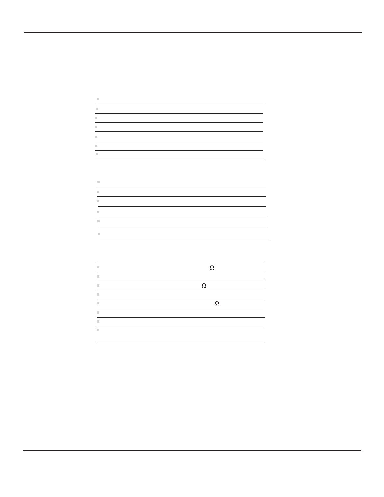
SPECIFICATIONS (Microphone - Model A)
Type
Output
Frequency response
Current drain
Supply voltage
Dimensions
Weight
SPECIFICATIONS (RN-2)
Input Impedance
Output Impedance
Output Gain
Electret Condenser
Line Level (0 dB 600W @ 1 kHZ)
50 Hz to 15 kHz
10 mA
12Vdc
4"Dia x 1 ½"H
3.5 oz
20kW
1k @1kHz
Ω
+5dB
Dimensions
Weight
Shipping Weight of kit
6 1/8“L x 4 5/8 “W x 1 1/4”H
5.5 oz
3 lbs
SPECIFICATIONS (Base Station - APR-1)
Monitor output power
Audio output impedance
Audio input impedance
Freq. response
Headphone impedance
Power supply
Dimensions
Weight
Shipping Weight of kit
1W@8
600W @ 1kHzr
10K
100 Hz to 10 kHz
8 to 600
12 Vdc, 500 mA
8 ¼"L x 5 ¾”W x 1 3/8" H
1 lb 6 oz
4 lbs
LOUROE ELECTRONICS 6 9 5 5 VALJEAN AVENUE, VAN NUYS, CA 91406 TEL (818) 994-6498 FAX 994-6458
®
website: www.louroe.com e-mail: [email protected]
Page 6 of 8
(818)
Ask4_401_inst_2/15
Page 7

NOTES
INSTALLATION AND OPERATING INSTRUCTIONS
IMPORTANT NOTICE
When this equipment is used as part of an
audio monitoring system, the law requires
that the public be given notice of AUDIO
MONITORING ON THE PREMISES. A
deca l notice is included with each
microphone shipped.
Federal Law References:
Federal Regulations, US Code, Title 18.
Crime and Criminal Procedure, Sec 2510.
LOUROE ELECTRONICS warrants that at the time of shipment products manufactured by LOUROE ELECTRONICS to be free of defects in material and workmanship.
Should a defect appear within one year (12 months) from date of shipment, LOUROE ELECTRONICS will, at its sole discretion, repair or replace the defective equipment.
This equipment shall not be accepted for repair or return without prior notification by LOUROE ELECTRONICS .
This warranty does not extend to any Louroe product that has been subjected to improper or incorrect installation, misuse, accident, or in violation of installation
instructions provided by LOUROE ELECTRONICS.
Returned shipments to LOUROE ELECTRONICS shall be at customer’s expense. LOUROE ELECTRONICS will return the equipment prepaid via best way.
®
®
®
WARRANTY
AUDIO
MONITORING
On
These Premises
®
®
®
®
LOUROE ELECTRONICS 6 9 5 5 VALJEAN AVENUE, VAN NUYS, CA 91406 TEL (818) 994-6498 FAX 994-6458
®
(818)
website: www.louroe.com e-mail: [email protected]
Page 7 of 8
Ask4_401_inst_2/15
Page 8

MANUFACTURED
IN THE
LOUROE ELECTRONICS 6 9 5 5 VA L J E A N AVENUE, VAN NUYS, CA 91406 TEL (818) 994-6498 FAX 994-6458
®
website: www.louroe.com e-mail: [email protected]
Page 8 of 8
(818)
Ask4_401_inst_2/15
 Loading...