


Octado
Instructions
Introduction ..................................................................................................................................... 1
Assembly tips and information ........................................................................................................ 2
Assembly of the Octado .................................................................................................................. 3
Assembly of the mechanical dobby ............................................................................................... 24
Installing the electronic interface ................................................................................................... 35
Tips and tricks for using the loom .................................................................................................. 35
Trouble shooting ........................................................................................................................... 38
Warrantee and contact .................................................................................................................. 40
Version: I_Octado_V4_EN


1
Introduction
Octado’s countermarch action produces a perfect shed automatically
The Octado is not literally a countermarch loom although it has all the advantages of one. In
countermarch looms, the shafts move both up and down so that tension on both raised and lowered
warp threads is equal. With the Octado, as the treadle is depressed, the rising shafts move, and as
they rise, the back part of the loom also rises. This action automatically creates a shed of raised and
lowered threads that is progressively greater toward the back and therefore completely even at the
front in addition to equalizing tension on all warp threads.
Loom at rest Progressive shed achieved during treadling
Octado treadling is very light
When a shed is formed on most looms, the activated warp threads move through a greater distance
than they do at rest. This means that the activated warp threads are under greater tension, and they
become stretched. If the warp is of an inelastic material and held at high tension, the force required
to treadle can be considerable. With the Louët Spring and Delta countermarch looms, this problem
is overcome to some degree: The breast beam moves during treadling to decrease the distance
between front and back beams, therefore decreasing the distance the through which the activated
threads move. With the Octado, the problem is completely overcome: Not only does the back part of
the loom move up, but the back beam also moves a little towards the breast beam during treadling.
This causes activated warp tension to decrease from even its resting tension—actually helping you
make the shed!
Accessories
Besides the choice of a mechanical or an electronic dobby head, you can obtain a full range of
accessories:
- Adjustable bench (59-72 cm)
- Tilting set for bench
- Second warp beam with back beam
-
Sectional warping
- Flying Dutchman shuttle
- Fly shuttle device
- Treadle height adjusting blocks
-
Program bars in sets of 10

2
Assembly tips and information
Barrel nuts
For the assembly of the looms, we use many barrel nuts and bolts to connect parts. The cylinder
shaped nuts have a slot on one of the flat sides. Always insert the barrel nut into the wooden part,
so that the slot in the barrel nut is visible. The slot shows the direction of the threaded hole in the
nut. With a flat screwdriver you can turn the barrel nut so that it is positioned properly to catch the
bolt. If you have a problem inserting the bolt into the barrel nut, try turning the barrel nut 180
degrees. This usually helps.
Carriage bolts
In other locations, we use carriage bolt to assemble wooden parts. These bolts have a square
enlargement (neck) under the bolt head. When you tighten the nut on the bolt, this square neck
locks into the wood to prevent the bolt from turning. In some instances, you will notice, that the bolt
is just a little too short for assembly with the washer and nut. We advise you to put the nut on the
bolt without the washer, and then tighten the nut sufficiently, so that the square neck pulls into the
wood. At this stage, unscrew the nut, install the washer and then replace and secure the nut again,
tightly. Alternatively, you can carefully tap against the bolt head with a hammer, until the bolt head is
secured into the wood.
Washers and spacers
For the proper operation of the loom, it is very important that you follow the proper assembly
sequence of the bolts, washers and spacers. Please carefully follow the instructions. To help you,
we have assembled all the washers and spacers in the hardware bags in the right sequence.
Wood screws
Where wood screws are used, we have pre-drilled holes in the wood. The screws will cut their own
thread into these holes. Please note however, that the screws are very sharp, and will cut into the
full wood outside the pre-drilled holes, if you miss the pre-drilled hole during assembly. However if
this happens, you will notice that after a couple of turns, it becomes very hard to turn the screw.
There is even a chance that the screw will twist off. Moreover, the part will be assembled in the
wrong location.
If you have to assemble and disassemble the loom several times, make sure that the wood screw
turns in the same thread again which was cut the first time. If not, the hole in the wood will become
too large for the screw. To find this screw thread, turn the screw anti clock wise while you push it,
until you "feel" the screw "drop" into the threaded part in the wood.
Markings
Many parts of the loom have been marked with letters of the alphabet at places where they have to
be connected to another part, marked with the same letter.
The first time a part is named in this instruction; these letters are mentioned, to indicate which part is
meant.
Tools
All parts used for the loom are metric. To facilitate the assembly, we have included two metric
wrenches (10 mm for m6 and 13 mm for m8) and a pz2 cross head screwdriver (not a Phillips
head!). Together with hardware bags 1, 2 and 5, these tools are located in box B.

3
Assembly of the Octado
Octado parts per box
The assembled castle of the loom is packed
in box A.
The handle for the beater is packed on top
of the shafts.
The parts shown here are packed in box B,
together with the hardware bags, two
wrenches and a screwdriver.
1. side rails L+R
2. front uprights L+R
3. beater uprights L=R
4. treadle sides L=R
5. hinged arms L=R
6. brake pedal
7. floating arms L+R
8. back uprights L+R
9. middle uprights L+R
10. lower side rails L+R
11. cloth beam lever
12. brake disk
13. warp beam crank
The following parts are packed in Box C,
together with 600, 800 or 1200 Texsolv
heddles 33 cm:
14. sixteen warp sticks
15. two lease sticks
16. two apron rods
17. reed
18. two treadle rails
19. three frame rails: foot rail, back rail and
back beam.
20. breast beam
21. warp beam
22. cloth beam
23. upper reed holder
24. lower reed holder
600, 800 or 1200 Texsolv heddles 33 cm
There is also a mechanical dobby (2 boxes) or electronic interface (1 box) for your loom.
4
1. Assembly of the side rails to the center frame
Use sawhorses or a table to support the
castle frame at least 25” (64 cm) above the
floor.
Open hardware bag # 1 containing the
following:
- 1 large ratchet
- 1 screw 4.5 x 20 mm
- 10 threaded rods m6 x132mm with cap
nut, washer and barrel nut
- 4-carriage bolts m8 x 55 mm with large
washer, 2 small washers and cap nut
- 2 screws 5 x 40 mm
- 4 buffers with m6 threaded end
- 1 screw 4 x 17 mm
-
1 piece of Texsolv cord 13-3/4” (35 cm)
Take the second side rail, marked JD, and
screw the large ratchet to it with screw
4.5 x 20 mm. Once tightened, loosen the
screw slightly to allow the ratchet to rotate
freely.
Remove the barrel nuts from two threaded
rods and put the barrel nuts in the
respective holes where the side rail needs to
be mounted to the castle frame.
Make sure that the grooves in the barrel
nuts are vertical.

5
Insert the 2 threaded rods, with washers and
cap nuts, from the top, through the holes in
the small side of the right side rail.
Assemble the side rail to the castle frame by
screwing the threaded rods with cap nuts
into the barrel nuts. Do not tighten the nuts.
The side rail still needs to be loose.
A hinged arm needs to be attached before the left side rail is assembled. Besides two holes for the
assembly with carriage bolts, there is a row of small holes for the installation of small hooks which
are required if the Octado has a second warp beam or a sectional warp beam.
The two hinged arms are identical, however, as soon as you insert a carriage bolt into one, it
becomes either a right hand or left hand hinged arm.
Take a hinged arm out of Box B and install a
carriage bolt into it.
Refer to the diagram to see where the row
with small holes is in relationship to the
carriage bolt.
Slide the large washer and then the two
small washers over the end of the carriage
bolt. Slide the carriage bolt from the outside
through the ball bearing in the left side rail.
The inside can be recognized as the side
with the circular groove for the cloth beam.
Put the cap nut on the end of the carriage
bolt and tighten with the 13 mm wrench.
During the assembly of this side rail you
need to lift up the first two shafts in order to
be able to access the screw hole in the
front.
The shafts are blocked with the screw heads
on the dobby bars at the side of the castle.
Push in the bars for shaft 1 and 2, which will
allow you to lift up shafts 1 and 2.
To keep the shaft in this position, you can
put a book or something similar between the
top shaft bars.

6
The left side rail can now be attached to the castle frame with two screws 5 x 40 mm. Insert these
screws from inside through the side of the castle. Do not tighten the screws completely and allow
the front screw about ¼” (5 mm) of clearance. This clearance is required to install the cloth beam
later during the assembly process.
2. Assembly of the sides and the installation of the cloth beam
Take the lower side rails (AE and BF) and
the front uprights (IE and JF) out of box B.
Install the four buffers (feet) by screwing
them in the pre-drilled holes as shown in the
diagram.
Make the J-J connection: Slide the upright
onto the wooden pins (dowels) of the right
side rail.
Insert a barrel nut into the side rail.
Insert the threaded rod with washer and cap
nut into the upright and tighten with the 10
mm wrench.
Assemble the left side upright in the same
way. (Connection I-I)
7
Take rear uprights AC and DB from box B
and assemble to the lower side rails
(connection A-A and B-B).
Insure that the holes for the connections C,
E, D and F are facing the same direction, so
that the holes for the barrel nuts are at the
same side of the connected parts.
Assemble the rear uprights and lower side
rails on both sides of the loom (Connections
D-D, F-F, C-C and E-E).
First slide the wooden parts over the dowels
and then make the connections with the
threaded rods, barrel nuts washers and cap
nuts.
Slide the cloth advance lever (from box B)
onto the cloth beam (from box C) and make
sure that the ratchet is on the right side of
the ratchet wheel.
Install the cloth beam with the wooden end
into the hole of the right side rail and the
metal end into the circular groove of the left
side rail. Be sure that the big ratchet is
turned in the backward position.
Because the side rails are not tightened yet,
you can push the side rails apart and install
the beam in between them.
Now tighten the left side rail with the two
screws.
The right side rail has to be tightened later,
after the sides of the loom are connected
with the foot and rear rails.

8
Take the last screw out of the hardware bag,
install it in the hole in the right side rail, and
leave the head of the screw protruding
approximately ¼” (5 mm).
Hook the end of the Texsolv cord to the
screw head. Guide the cord under the
handle of the cloth advance lever and hook
the other end also to the screw head.
The Texsolv cord is cut on the joint between
two holes. The first hole is not strong, thus
unreliable and is not to be used. We always
use the second hole as first reliable hole.
There are now three carriage bolts, washers and cap nuts left over in hardware bag #1. This
hardware is required to attach of the rear part of the loom to the hinged arms, as will be described
later in these instructions.
Open hardware bag # 2 with the following
contents:
- 20 screws 5 x 50 mm
- 4 screws 5 x 40 mm
- 1 carriage bolt m6 x 40 mm with washer,
piece of nylon tube, 12 mm spacer
bushing, washer and cap nut m6.
- 1 screw eyelet
- 2 screws 4 x 21mm
- 2 buffers
- 4-carriage bolts m8 x 70 mm with large
washer, spacer 17 mm and cap nut m8
In Box C are five long straight rails with screw holes in the ends. The two shorter rails of the same
length are used with the treadle. The three longer rails are the foot rail, the back rail and back
beam.
Put the 4 screws 5 x 50 mm in the holes of
both rear uprights.
Hold one side of the back rail against the
back upright. Use the screws to locate the
holes in the back rail and turn the screws by
hand one turn.
This side of the back rail will now hang on
the tips of the screws and you will have your
hands free to do the same on the other side.
Now use the screwdriver to tighten all four
screws.

9
In the same way install the foot rail on the
front of the loom, between the front uprights.
For this there are 4 holes for the screws in
each upright (this is different than on the
picture).
The foot rail can be installed at two different
heights, depending on the length of the legs
of the weaver. For most weavers the lower
position of the foot rail will be preferred.
The frame of the Octado is complete and
now you have to tighten the cap nuts of the
connection between the right side rail and
the castle. The sawhorses or table is not
required anymore and can be removed.
3. Assembly of the back part with warp beam and the treadle
Slide the brake disk onto the longest one
of the protruding shaft of the warp beam;
the sides marked Q must face each other.
Attach the brake disk with four 5 x 40 mm
screws and make sure the screws are
tight.
Take the two vertical posts of the back part
out of box B. You can recognize these
posts by the two holes with ball bearings.
The right hand vertical post has a hole for
the longer shaft of the warp beam to go
through. Attach to this vertical post the
attachment bolt for the brake cable: Insert
the carriage bolt m6 x 40 mm into the hole
near the ball bearings, so that it protrudes
at the side where the black nylon bearing
is situated besides the hole for the warp
beam axle.
Slip on a washer, the piece of nylon tube
that will center the spacer bushing, slip on
that bushing, the second washer and
tighten the cap nut.

10
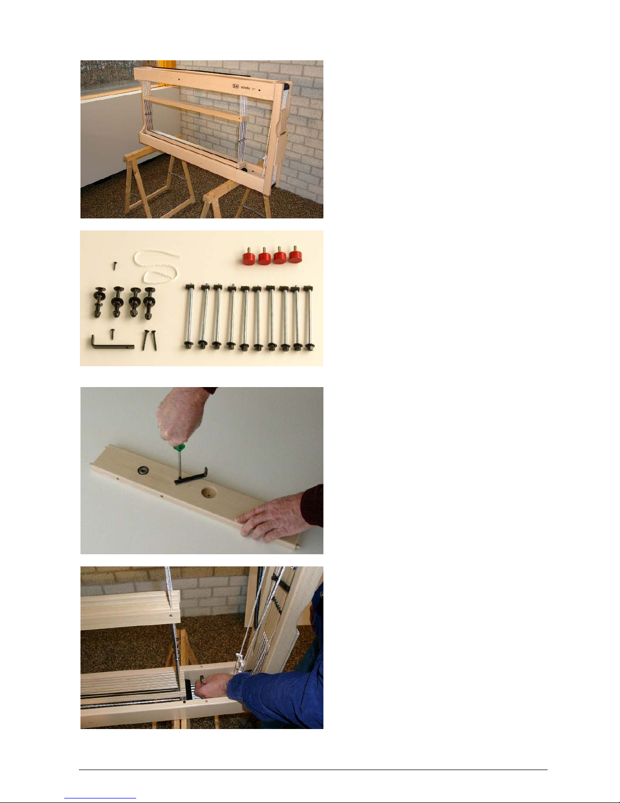
Now turn the screw eyelet into the small
side of the upright, until the entire threaded
part is into the wood.
Attach the right hand upright to the back
beam with two screws 5 x 50 mm.
Insert the long shaft of the warp beam
through the right upright and slide the left
upright onto the short shaft on the other
side of the warp beam.
Also attach this upright to the back beam
with two screws 5 x 50 mm.
Now we are going to assemble the back
part (assembly of two uprights, warp beam
and back beam) to the hinged arms and
the loom. You will need the last three
carriage bolts, washers and cap nuts from
hardware bag #1.

11
Put a carriage bolt through the hole in the
hinged arm that is connected to the left
side rail. First slide the large washer and
then the two small washers onto the
carriage bolt.
Place the back part onto the protruding
lower side rails and guide the carriage bolt
of the hinged arms through the ball
bearings of the left upright.
Hold the hinged arm and the upright and,
using a hammer, tap the head of the
carriage bolt until there is sufficient thread
showing through the ball bearing to put the
cap nut onto the bolt. Tighten the cap nut
with the 13 mm wrench.
Install the remaining two carriage bolts
from hardware bag # 1 onto the other
hinged arm. Pay particular attention to the
position of the small holes; the hinged
arms need to be mounted opposite to one
another (in mirror image to each other).
Slide the large washers and then the two
smaller washers onto both carriage bolts.
Slide the bolts, through the ball bearings of
the side rail and at the same time through
the ball bearings of the right upright of the
back part.
Tighten the assembly with the cap nuts.
12
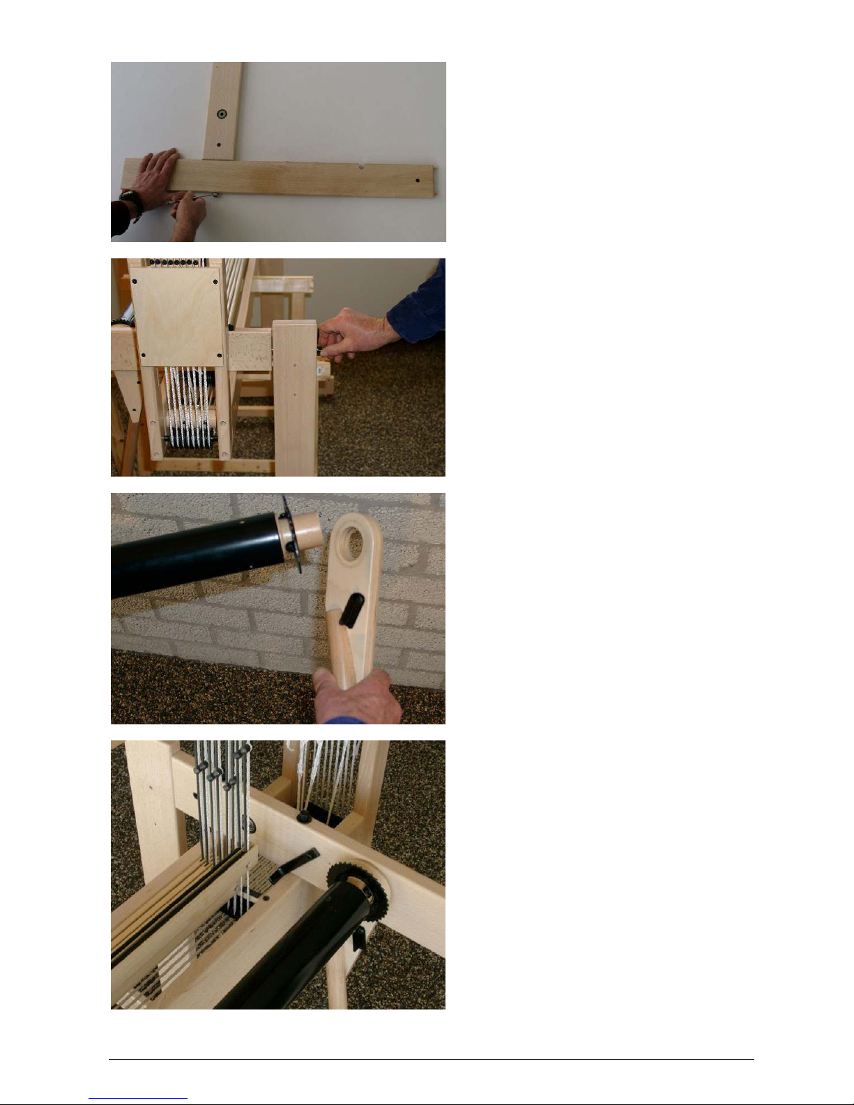
Take the two treadle sides from box B.
Attach the buffers with the 4 x 21 mm
screws onto the angled corners.
Tap two of the m8 x 70 mm carriage bolts
into the holes of a treadle side and slide on
the large washers and 17 mm spacer
bushings.
The treadle sides are identical, but the
direction of the carriage bolts determines
whether the side becomes the right or left
side.
Attach the treadle sides by placing the
ends of the carriage bolts through the ball
bearings from the inside of the uprights.
Put the cap nuts on the bolts and tighten
with the 13 mm wrench.
Both treadle sides are installed this way.
We now connect the treadle sides by
installing the two remaining rails between
them with the 5 x 50 mm screws.
Put two screws through the holes of one
treadle side. Hold the rail in position and
locate the tip of the screws, guiding them
into the holes in the rail.
Turn the screws by hand one turn. The rail
will now hang by itself. Do the same on the
other side.
Tighten all four screws half way in with the
screwdriver.
The other rail is meant to push the treadle
to the floor. There are three sets of holes
in the treadle sides. These holes can be
used to adjust the treadle in three
positions, depending on the length of your
legs.

13
Install this rail with four screws in the same
way and tighten the screws of both rails
firmly with the screwdriver.
4. Attach the treadle and adjust the height of the dobby knife
Open hardware bag # 3 with the following
contents:
- 1 heavy, big screw eyelet
- 1 screw 4 x 17 mm
- 2 Texsolv cords, 24 ½” (62 cm) and 12”
(30 cm) long
- 1 hook with washer and nylon knurled
nut
Turn the screw eyelet into the right hand
treadle side until just the entire thread is in
the wood.
This eyelet needs to be connected with the
longer Texsolv cord to the knife pulley in
the castle. The hole is under an angle, so
you can turn the eyelet aligned in the
direction of the knife pulley.
Screw the 4 x 17 mm screw in the upright
of the frame until the screw head protrudes
approximately ¼” (5 mm).

14
Turn the knife pulley slightly by pulling on
the cords and hook the end of the longest
of the two Texsolv cords around the screw
head on the knife pulley.
Guide the cord one and a half turn around
the knife pulley, clockwise, when looking
from the front of the loom.
Put the plastic hook with washer and
knurled nut through the eye of the treadle
and attach the second hole of the cord to
the hook (Do not count the hole where the
cord is cut).
Use a black felt tipped marker to mark the
hole in the cord that is 19 1/4” (49 cm)
above the floor and remove the cord from
the plastic hook again.
15
Insert the short cord into the marked hole,
and then put it through its own end.
Pull the short cord so that it is secured with
a tight loop to the larger cord at the
marked hole.
Attach the end of the first cord, again with
the hook, to the eye of the treadle.
The other cord needs to be attached to the
screw head on the upright. Choose the
hole in the cord that results in a nice
winding on and off on the knife pulley
when you move the treadle up and down.
The cord on the knife pulley should not
scrape the wood or the screw head.
Use the knurled nut of the attachment to
the treadle to adjust the height of the
dobby knife. The dobby knife is the black
metal bar that goes up and down when
you turn the knife pulley.
In its neutral position, the dobby knife
should be high enough that the screw
head of the last dobby hook can move
freely below it if the dobby hook is pushed
forward. Leave about ¼”- ½” (5 - 10 mm)
clearance.
5. Assembly of the warp beam brake
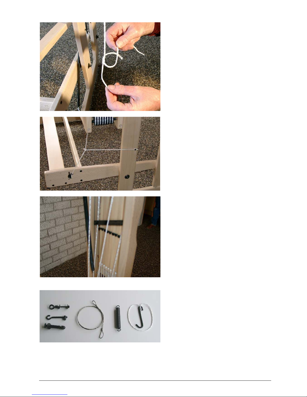
Open hardware bag # 4 with the following
contents:
- 1 threaded eye m6 x 60 mm with two
nuts m6, 2 washers and one nut m6
- 1 threaded hook m6 x 60 mm with
barrel nut m6
- 1 carriage bolt m8 x 70 mm with large
washer, spacer bushing 36 mm, small
washer and cap nut m8
- 1 spring for brake
- 1 brake cable
-
1 hook with 15 ½” (39 cm) cord
16
Push the carriage bolt through the hole in
the upright of the back part from the
outside of the loom. Slide the large washer
and the 36 mm spacer bushing over the
carriage bolt.
Place the barrel nut into the hole of the
brake pedal and turn the threaded hook so
far into the nut, that the threaded end
sticks about 1-3/4” (2 cm) through.
Slide the brake pedal over the spacer
bushing onto the carriage bolt, than the
small washer and the cap nut. Tighten the
cap nut well.
Take the threaded eye and remove a nut
and one washer.
Put the threaded eye through the hole in
the brake pedal.
Replace the washer and nut and tighten
the nut. Make sure to put a screwdriver
through the eye and line-up the direction of
the eye with the eye in the upright of the
back part of the loom.

17
Hook the brake spring to both eyes.
Position the large eye of the brake cable
over the end of the carriage bolt and guide
the cable one turn around the brake disk.
Put the eye on the other end of the brake
cable over the hook of the brake pedal
while you push the brake pedal down.
When you let go of the brake pedal, its
position should be approximately
horizontal. If not, you have to adjust it with
the threaded hook at the end of the pedal.
Shorten by screwing the hook in more, you
will lower the pedal. Of course you have to
unhook the cable before turning the hook
inward or outward.
Take the hook and cord out of the
hardware bag. Guide the cord around the
stem of the screw eye of the pedal and
attach it to the hook.
You can put the hook around the spacer
bushing of the hinge point of the back
frame.
This will take the tension from the brake
cable, and allow you to beam-up the warp
without having to keep the brake pedal
pushed in all the time.

18
You can adjust the friction of the cable and make the warp beam run just light enough by
adjusting the length of the cord longer or shorter. It also makes a difference if the cord runs over
the nuts or just besides the eye.
You should hang the hook on the screw
eye when not in use; otherwise it can
damage the wood when the back beam
section goes up and down.
6. Assembly of the breast beam
Open hardware bag # 5 with the following
contents:
- 1 carriage bolts m8 x 55 mm with large
washer, 22 mm spacer bushing, small
washer and cap nut
- 6 screws 4 x 17 mm
- 4 screw eyes
- 2 springs, 12” (30 cm) long with a 15
½” (39 cm) long cord
-
2 cords, 8 ½” (21 cm) long
Take the wooden posts marked K and L
out of box B. These wooden posts will
support the moving breast beam.
Support the wooden posts, and tap the
carriage bolts into the holes. The markings
(K and L), need to be on the side where
the bolts stick through the holes.
Slide the large washer and spacer
bushing, over the carriage bolt and attach
the wooden posts to the front uprights of
the loom. Make sure to connect K-K and LL. This determines left and right.
Use the small washers and cap nuts to
finish the assembly.

19
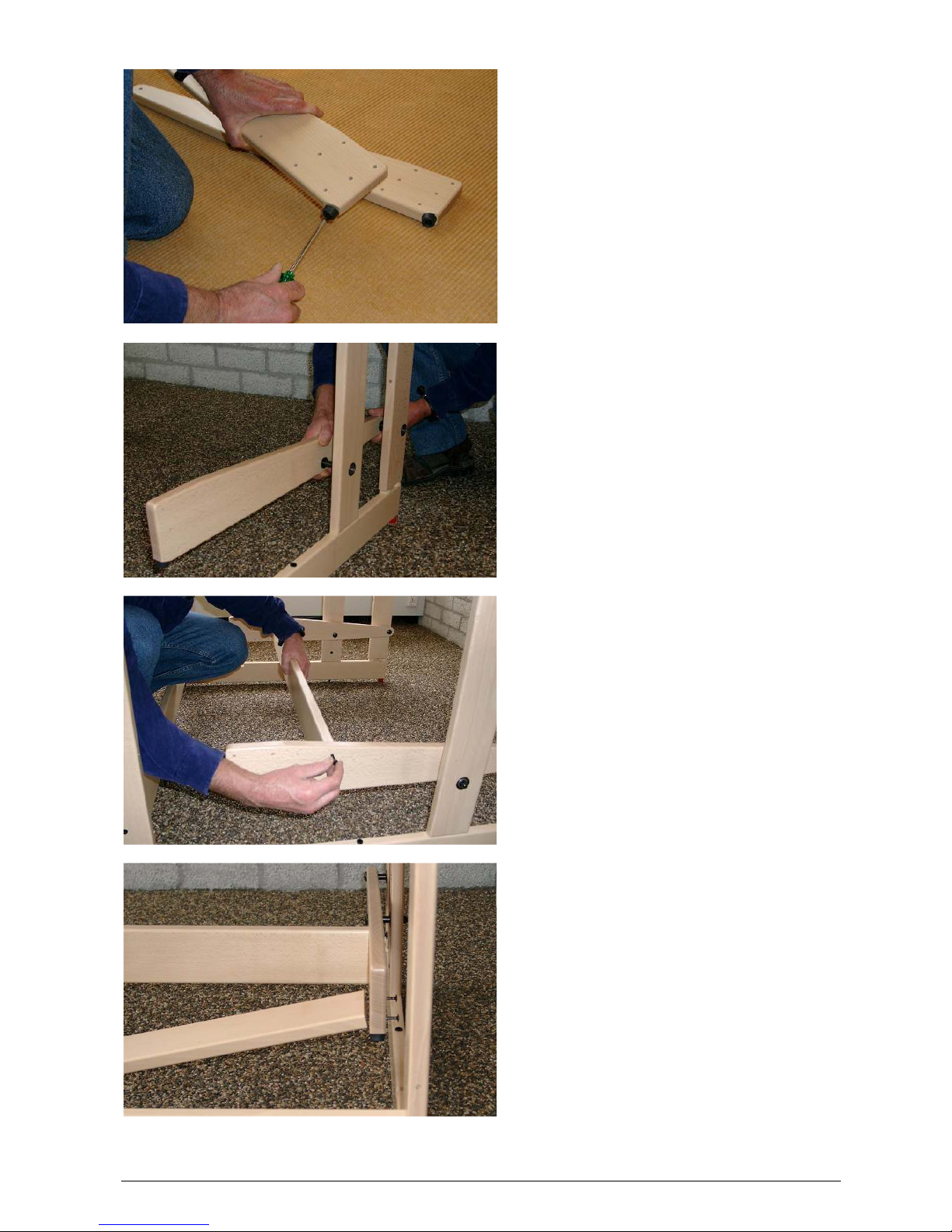
Put two screws in each wooden post and
one in the back of the upright.
The heads of these screws need to stay
¼” (5 mm) above the wood.
Connect the lower two screws on both
sides of the loom with a cord.
This cord will lock the breast beam to get
an even tension when you attach the warp
to the cloth beam.
Slide the breast beam onto the pins of the
wooden posts; first on the one side partly,
and then on the other side.

20
Put two of the screw eyes in the
appropriate holes in the sides of the loom,
and hook the springs onto these eyes.
By connecting the cords of the springs to
the screws on the spring arms, you make
the breast beam movable. You will use this
system later to regulate the warp tension
Put the two remaining screw eyes into the
uprights of the back beam section.
Later on you will attach the cross sticks to
these if you warp in that way.
This will leave the cross sticks between the
warp beam and the back beam, when you
advance the cloth.
7. Assembly of the beater
Open hardware bag 6:
- 2 beater hinges
- 2 lag bolts m8 x 90 mm
- 4 small washers m8
- 2 spacer bushings, 1 3/8” (33 mm) long
- 2 bolts m6 x 70 mm with washer and
barrel nut m6
- 2 carriage bolts m6 x 80 mm with
washer and wing nut m6
- 2 black buffers with m6 threaded end
- 8 beam cords, 66” (142 cm) long
-
3 strips of thin cardboard

21
Turn the black buffers into the top hole in
the side rails of the loom.
When you install a fly shuttle, you need to
install these buffers into the bottom holes.
Connect the lower reed tray (the one with
the slanted side) to the uprights: Place the
barrel nut into the hole on the end of the
lower reed tray. Slide the upright with the
slit in it, over the lower reed tray. Place the
bolt with washer in the hole and screw it
into the barrel nut. Tighten the bolt and, in
the same way, assemble the other up right
on the other side of the reed tray.
Turn the vertical hinges into the bottom of
the uprights. By turning these hinges in
and out, you can adjust the height of the
reed exactly after threading through your
first warp.
Place the assembly of uprights and lower
reed tray into the loom. First guide one
hinge along the side rail and then the
other.

22
Put the hinges into the openings in the
lower side rails.
Assemble the handle to the upper reed
holder: Slide a washer over the lag bolts
and then put them through the holes in the
upper reed holder.
Next slide another washer and a spacer
bushing over the lag bolts.
Hold the handle with the holes over the
points of the lag bolts and then tighten the
bolts so far that the spacer bushings are
tightened slightly into the handle.
Tap the carriage bolts into the holes at the
end of the upper reed holder. Support the
reed holder by putting it on the side rails of
the loom. Make sure that the handle is
facing up.
Slide the washers over the carriage bolts
and twist the wing nuts a couple of turns
onto the carriage bolt. Assemble the upper
reed holder to the uprights. Slide the
carriage bolt from the top into the slots and
insure that the washers rest under the
wing nuts and not between the upright and
the reed holder. Keep this in mind when
you change your afterwards.
Fasten the wingnuts, while you keep the
top reed holder parallel to the lower one.
You can also do this by placing a reed in
between.
Move the beater backwards, so it rests
against the buffers at the sides of the
castle frame.

23
Now we will check if the beater is even and make a correction if necessary. Take the beater by its
handle and pull it towards you, one or two inches. If the beater is even, both uprights will leave the
buffers at the same moment and also tough the buffers at the same time when you let the beater go
back and rest against them. If this is not the case, the beater is not even and you will correct that
with the small cardboard strips from the hardware bag.
The upright that leaves the buffer latest
when you pull the beater, is the one that
needs one or more cardboard strips in its
slit connection with the lower reed holder.
Unscrew the m6 bolt several turns, so that
some play is created in this connection.
Slide a cardboard strip completely into the
slit at the bottom and fasten the m6 bolt
again.
Check if the beater is even now, and if not,
use one or two more strips in the slit.
Hook the end of the tie-up cords around
the screw heads of both, cloth beam and
warp beam. Hardware bag 6 is the same
for Octado 70 (28”) Octado 90 (36”) and
Octado 110 (44”). So with the Octado 70
and 90, you will have extra tie-up cords,
which will not be used.

24
Assembly of the mechanical dobby
This part of the instruction manual can be ignored if your loom has an electronic interface.
The mechanical dobby has a roller that is activated by a treadle. There is a chain with selection bars
that runs over the dobby roller. Every time you push the dobby treadle in, the dobby roller turns 90
degrees and brings a new selection bar in position and a new selection for the shafts is created. You
can program a pattern by putting little pegs in the selection bars. These pegs push the dobby hooks
into their active position: The screw head on the outside of the dobby hook no longer blocks the
movement of the shaft, and the screw head on the other side of the dobby hook will be picked up by
the dobby knife if you depress the lifting treadle.
Parts of the mechanical dobby:
1. dobby head
2. dobby treadle
3. reversing disk with hardware (the hardware differs from the above picture, since we have
improved the system, see picture below) and blocking block
4. guide block for cord, complete with three pulleys
5. guide block for cord, complete with one pulley
6. 20 selection bars, connected with 40 grey pegs
7. 100 black pegs and 3 grey pegs
8. sheet with labels
9. hardware bag
10. footrest
In the picture the new hardware of the reversing disk is
shown. This new hardware will improve the adjusting of the
cords between the reversing disk and the anchor and the
cord that connects the locking block to the dobby treadle.

25
In the picture 4 wooden pegs are shown, these were
used in the past, but are no longer needed.
Open the hardware bag:
- 1 lag bolt m8 x 60 mm
- 1 large washer m8
- 1 small washer m8
- 1 spacer bushing 22 mm long
- 1 screw eye
- 1 screws 4 x 17 mm
- 2 black buffers with m6 threaded end
- 2 carriage bolts m6 x 50 mm with
washer and nut
- 2 screws 4 x 35 mm
- 1 screw 4 x 30 mm
- 2 screw hooks
- 1 anchor
- 2 cords, 59” (150 cm) and 42 ½” (108
cm) long
-
1 spacer bushing 12 mm long
The dobby hooks are located between two
uprights. The rear upright has two holes in
it for the support of the dobby head.
Put a carriage bolt from the inside through
the top hole. You need to lift the cords one
by one over the head of the carriage bolt.
Slide a washer, the 12 mm spacer bushing
and another washer over the end of the
carriage bolt. Tighten the nut until the
square part of the bolt, just under the head
of the bolt, pulls completely into the wood.
Remove the nut, washers and spacer
bushing from the bolt again. Do the same
with the other carriage bolt in the lower
hole. This hole is located behind the dobby
hook guide plate.

26
Slide the dobby mechanism over the
carriage bolts, slip on the washers and
tighten it with the nuts.
The top hole in the dobby mechanism has
the form of a slot. You can make use of
this later when you adjust the proper
distance between the dobby head and the
dobby hooks.
Take the assembled chain of selection
bars and put the first one in the groove on
top of the dobby roller.
The grey pegs that connect the selection
bars are sturdier than the black ones,
which are used to program the pattern.
Turn the top of the dobby roller towards
the top of the loom. Guide the first
selection bar between the guide disks.
These are two washers, situated just
below the dobby roller on the mounting
board.
27
Connecting the first to the last selection
bar requires a bit of skill. The hinges of the
connecting links, left and right, need to be
pushed together at the same time.
From the inside, insert a grey peg through
the hinges until it comes through with a
click. If you want to take the pegs out
again, it is helpful to first push the part of
the peg that sticks out, to the inside.
Put four black pegs in alternating holes on
the first selection bar.
Turn the dobby roller and make sure that
the pegs on the selection bar push the
dobby hooks forward.
Loosen the nut of the upper carriage bolt
that connects the dobby head to the loom
and now you can fine tune the location of
the dobby head relative to the dobby
hooks.
The pegs need to push the dobby hooks
so far that they almost touch the dobby
knife. When this has been accomplished,
tighten the nut of the carriage bolt again.
Screw the two buffers into two of the four
holes in the front of the right hand upright.
Depending on the chosen height of the
foot rail, this will be the first and the third
hole, or the second and the fourth hole
measured from the bottom.

28
Take the treadle and turn the screw eye in
the hole at the end until the threaded part
is completely into the wood. The picture
shows how the eye needs to be located
relative to the treadle.
The 2 screw eyes should be screwed into
the little holes at the bottom of the dobby
treadle.
The hole left in the bar is from the old
system and is not used/drilled anymore.
Place a small washer and then the 22 mm
spacer bushing onto the lag bolt. Put the
bolt through the hole at the other end of
the treadle and slide the large washer
around the lag bolt. Watch out that the
head of the lag bolt sits on the same side
as the screw you just installed.
Tighten the lag bolt to the front of the left
upright. Again, you choose the hole
depending on the position the foot rail has
been mounted. You can let the other end
of the treadle rest on the lower buffer.
Take the cord guide block with one pulley,
and take the pulley off.
Attach the guide block with the two 4 x 35
mm screws to the inside of the upright.
Insure that the shaft is angled towards the
loom.
Slide the pulley and cap back onto the
shaft.

29
Put the shaft of the locking block in the
hole of the lower side rail. Put a screw
hook further back onto the side rail and
hook the spring around it.
Hook the end of the cord that goes to the
locking block onto the threaded hook with
knurled nut on the treadle and guide the
cord over the pulley.
When you push the dobby treadle down,
the block will turn under the lifting treadle.
This block will prevent you from pushing
both treadles at the same time.
In the neutral position there is about 1/4”
(5-10 mm) space between the locking
block and depressed treadle.
Make the cord between locking block and
dobby treadle longer or shorter to adjust
the neutral position of the locking block.
Fine adjustment can be by turning the
knurled nut shown on the previous picture.
Put the carriage bolt of the reversing disk
through the hole in the right hand upright.
Slide the large washer onto the bolt and
then the ½” (12 mm) spacer bushing.

30
Next you slide the reversing disk onto the
carriage bolt and tighten the cap nut.
Turn the screw hook into the top of the
upright and attach the spring of the
reversing disk to it.
Take the guide block with three pulleys
and disassemble the carriage bolt with one
pulley. Put the carriage bolt from the inside
through the lower back rail of the castle.
Slide the guide block, the two washers and
the pulley onto the carriage bolt. Tighten
the cap nut while the guide block points in
about the same direction as on the picture.

31
The bent piece of steel wire in the
hardware bag is the anchor. The anchor
will pull the dobby roller a quarter turn
every time you depress the dobby treadle.
Take the longer of the two cords. Put the
end through the last hole in the other end
to make a loop. The anchor goes through
the loop.
Mounted at the backside of the reversing
disk are threaded hooks to connect the
anchor cords to. Insert the end of the
longest anchor cord through the screw eye
on top of the reversing disk and attach the
second or third hole of the threaded hook.
Do the same with the other anchor cord at
the bottom of the reversing disk.
With the white nylon nuts you can adjust
the length of the cords.
Now connect the reversing disk with the
dobby treadle. Put the hook with washer
and knurled nut from the bottom through
the eye of the treadle and hook the cord to
it. You can adjust the cord by putting the
hook through a different hole, or for finetuning, use the knurled nut.
Slip the spring to one side of the brace of
the disk. Now the cord needs to be so tight
that it keeps the brace in a horizontal
position.

32
Guide the anchor cord from the top of the
reversing disk behind the upright of the
beater to the angled guide block with the
pulleys. This cord needs to go around the
higher of the two lower pulleys and then
over the third pulley and up.
The cord has to go over the highest pulley
on the dobby head. The anchor needs to
be attached to two of the four rollers that
are on the back of the wooden knob on the
dobby roller.
Make a loop in the other anchor cord and
attach it to the other side of the anchor.

33
Guide the cord around the pulley, over the
lower pulley of the angled guide block and
to the reversing disk.
Attach the cord in the same way to the two
screws on the lower point of the reversing
disk. Remove the cord from one or two
pulleys; this will give you some slack,
which you will need to attach the cord. Put
the cord back over the pulleys.
Adjust the angle of the three-pulley guide
block. The two cords need to run parallel
to the guide block. Lock the guide block in
this position by screwing the remaining 4 x
30 mm screw into the guide block.
Now is the time to adjust the proper position of the reversing disk and the tension in the cords, see
next picture. The tension of the anchor cords can be a little less than the tension in the dobby knife
cords. The cords are connected to each other with the anchor, so the tension in both cords is the
same. If you tighten one cord, the tension in the other cord will increase the same.
The tension in the cords can be increased or decreased by putting the cord one hole more or less
onto the threaded hooks of the reversing disk. You will need to take the cords off one or two pulleys
in order to get some slack in the cord.

34
Move the spring to the middle of the brace.
Now you can move the reversing disk a
couple of mm. This is the same as the
slack that the anchor has on the two rollers
of the wooden knob.
The average position of the brace, taking
this slack into mind, has to be horizontal.
You can correct the position of the brace
by fine adjusting the tension of the cords
by turning the knurled nuts on the threaded
hooks.
.
Slide the spring to one end of the brace. With the dobby treadle you can turn the dobby roller a
quarter turn. If you put the spring on the other end of the brace, the dobby roller will turn in the other
direction.
By reversing direction, you can weave your programmed pattern in mirror image; i.e. weave forward
or backwards.
Use always more than ten selection bars.
If your pattern needs less, than repeat the
pattern on a longer chain of selection bars.
The round stickers can be used to mark
the selection bars. This will help you see
where you are in your pattern.
With the mechanical dobby we deliver a
footrest. You can use the footrest for your
left or right foot. When you rest your foot
on the footrest, you can use your heel to
operate the dobby treadle.

35
Installing the electronic interface
Please refer to the manual provided with the electronic interface for details on installing the
electronic interface.
Tips and tricks for using the loom
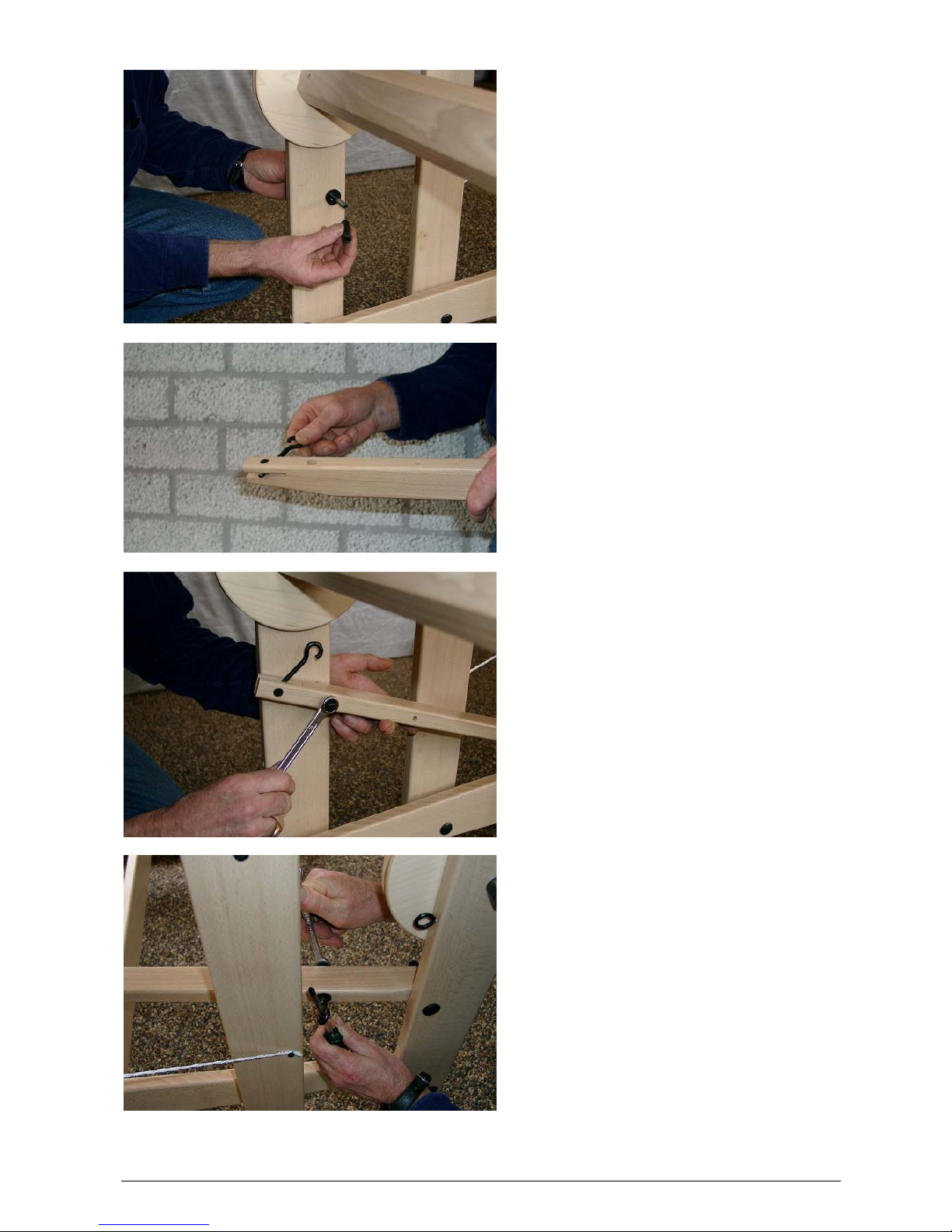
Installing the heddles to the shafts
With some weave structures there are many warp threads on the first two shafts. To help these two
first shafts moving down when the shed closes, we have added some additional weight to these
shafts.
To help the shafts slide properly along each other during weaving, it is necessary to have some
heddles at both ends of all shafts, especially when you weave a small project.
Texsolv heddles consist of a double
polyester cord that is connected at specific
distances. This chain of heddles is folded
in a zigzag fashion into bundles of one
hundred.
With a sharp pair of scissors, cut the loops
between the heddles.
Count the desired number of heddles for
each shaft and make bundles by tying the
heddles in four places. Always place more
heddles than you actually need on each
shaft.
The sides of the shafts are made from steel wire. The ends of the steel wire are bent 90 degrees
and the ends are put into a small hole in the end of the shaft bars.
Putting the side of the shaft into and out of the hole of the shaft bar is a little tricky. The groove at the
end of the shaft bars have a specific shape, so that the shaft end snaps into place the moment it is
at the proper depth in the shaft bar. When you remove a shaft end, you need to pull hard enough to
overcome this extra resistance. Make sure you keep the shaft end square relative to the shaft bar;
otherwise the bended end will bite into the wood.
When you put the end of the metal shaft side back in the hole, you can look at the hole in the shaft
bar. If the metal shaft side is in the middle of the hole, the metal shaft side is also in the middle of
the hole into where it has to be inserted.
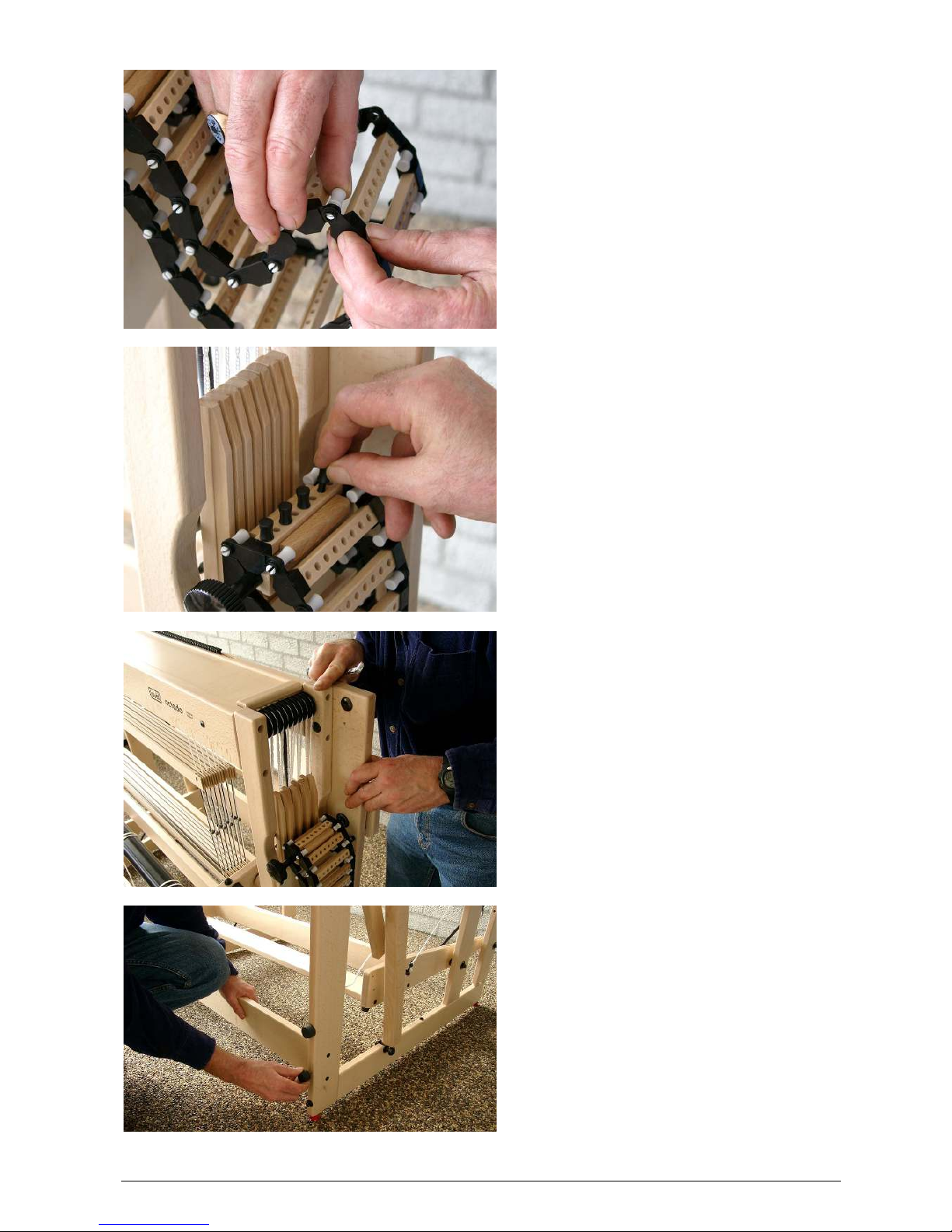
Push the dobby hook at the side of the
castle inward. This will unlock the shaft,
and you can pull the shaft up.
Put something (like a book) between the
shaft bars. Now the shafts you wanted to
lift will stay in a higher position.
Remove the shaft end from the upper shaft
bar, slide the bundle of heddles over the
shaft bar and click the shaft end back into
the shaft bar. Also position the cord back
into the groove of the shaft end.
36
Remove the two twist ties that keep the
upper part of heddles together.
Pull the lower shaft end out of the lower
shaft bar.
Slide the bundle of heddles over the shaft
bar. The heddles still have the lower two
twist ties attached.
Leave the shaft bar hanging in the
heddles, while you remove the last two
twist ties from the heddles.
Slide the heddles to the middle of the
shaft, click the lower shaft end back into
the shaft bar and put the cord back into the
groove. Now you can lower the shaft
again.
Repeat this process for all shafts.
If you want to remove heddles, you do the same procedure in reverse. Make sure you always take
care to put the four twist ties back on, before you remove heddles from the shaft bars.
Blocking the brake pedal during the beaming-up of the warp
During the beaming-up of the warp, you need to keep the brake pedal pushed down, or it needs to
be blocked in the down position by the hook that hangs on the eye of the brake pedal.
While pushing the brake pedal down, you can attach the hook to the bolt of the hinge point located
on the treadle where it is connected to the back part of the loom.

37
By changing the length of the Texsolv cord, you will adjust the friction of the brake. Adjust the friction
to the point where you can easily turn the crank on the warp beam, but where the beam does not
turn back by itself when you let go of the crank.
After unlocking the brake again, replace the hook onto the eye of the pedal, otherwise it can damage
the wood while the back part of the loom moves up and down.
Blocking the back part during the beaming-up of the warp
In order to prevent the back part of the loom from being pulled up during the beaming-up of the
warp, you need to block the back part in its lowest position.
If your Octado has a mechanical dobby, you can achieve this by taking off the spring that connects
the blocking block to the frame of the loom.
If your loom does not have a mechanical dobby, you can block the treadle and the back part by
putting some books under the treadle.
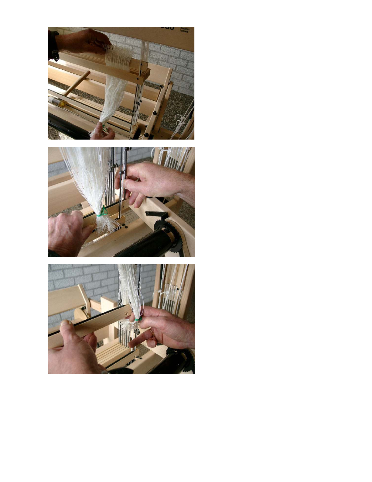
The tie-up bars and the tying-up of the warp to the cloth beam
The tie-up bar of the cloth beam is a bit shorter than the bar of the warp beam, because when you
beam up the cloth, it has to pass between the spring arms. Make sure that the tie-up bar does not
get caught behind the spring arm.
The tie-up bars are marked where the beam cords must be tied. Make loops in the cords and put the
tie-up bar through them. Position the loops on the pre-marked spots. Pull on the tie-up bar to check
if the cords are equally tight. If required, correct this by loosening the loops and then tightening them
up again by pulling on the tie-up bar.
The warp has to be tied to the cloth beam after it has been slayed. To do this, first remove the cloth
protector on the breast beam by unscrewing the plastic knurled bolts at both sides.
After the tie-up bar has passed the breast beam, when you have started weaving, you can put the
cloth protector back in place.
When you tie-up the warp, you will need to block the breast beam, otherwise it will be impossible to
get an equal tension in all the warp threads. Take the spring cords off the spring arms and while
tying on the warp, the breast beam becomes blocked by the cords that are connected from the
spring arms to the front posts of the loom.
The moving breast beam
You use the moving breast beam to set the warp tension. As long as you do not change the settings,
you will weave the whole warp with the same tension. The warp tension can be adjusted by
shortening or lengthening the spring cords, or by using the lower or top screw head on the spring
arms, to which you can attach the cords. Fastened to the top screw heads, the springs exert less
tension onto the breast beam. You will reach the highest warp tension when you pull out the springs
and attach them with a small piece of the cord to the lower screw heads.
Adjusting the height of the beater
The hinges in the bottom of the uprights of the beater are threaded. You can turn these hinges in or
out (on both sides of the loom), which allows you to adjust the height of the beater very precisely.
The height of the beater has to be adjusted, so that the warp threads rest in the bottom of the reed
on the shuttle race. This allows the shuttle race to properly support the shuttle. The reed and lower
reed support should not push the warp threads up. This would result in the heddles eyes resting on
the warp, so that the shafts, which have to be kept down during a shed, would not be locked in the
lower position.
You can check the horizontal position of the beater by lowering your eye to a point, where you can
compare it with horizontal parts of the loom like the shaft bars.
Beaming up the cloth during weaving
Lightly push the brake pedal of the warp beam. The breast beam will, due to its spring supports, pull
a bit of warp from the warp beam and move it to the front.
Now crank the cloth beam up and when the spring arms of the breast beam are back in the same
position as before you released the brake, you will have the same amount of tension in the warp.
The first beatings after advancing the cloth always influences the warp tension a little and you may
have to correct this by cranking up the cloth beam by one tooth of the ratchet wheel. If you crank up
the warp too tight (the spring arms are pulling the springs too far), you can release it by pushing in
the brake pedal just a bit.

38
If you advanced the cloth too far, you can reverse it as follows:
- Release the warp tension by pushing the brake pedal.
- Take both ratchets out of the ratchet wheel of the cloth beam and turn the beam backwards.
- Return the ratchets into the ratchet wheel again.
- While pushing the brake pedal down, beam the warp back onto the warp beam.
- Beam up the cloth until the spring arms reach their vertical position in which they produce the
warp tension that you have previously chosen for your weaving project.
If you beamed back too far, advance the cloth to its proper position.
Points of attention
1. Do not remove the ties from the bundles of heddles before the shafts bars or something else has
been put into the heddle loops. The ties are required to keep the heddles properly organized.
2. Do not leave the cross sticks in the warp between the back beam and the shafts, while weaving.
The effective depth of the loom would be reduced and the warp would be subjected to an
excessive amount of tension when creating the shed. If you are used to leaving your cross sticks
in the warp, you have to attach them to the two eyelets at the back of the loom. The cross-sticks
will then stay between the back beam and the warp beam when you advance the cloth.
3. For the mechanical dobby, do not change the dobby position while you push the treadle that
creates the shed. The treadle for the dobby system and the treadle for the shed are interlocked.
Only one can be operated at a time, the other is then locked. However, you can change the
dobby by hand when the shed treadle is pushed down. Should this accidentally happen, or if the
dobby knife becomes stuck between the screw heads for some other reason, you can easily
undo this situation: Turn the knob for manual operation 45 degrees and push down the shed
treadle and then let the treadle go up again.
4. The frontal shafts move less and are subjected to less force. If you do not use all the shafts, it is
advisable to leave the shafts in the rear un-used.
5. It is very important that the steel guides at the ends of the shafts are properly placed into the
shaft bars and that the cords are lying in the grooves of the bars.
6. Check that the washers are underneath the wing nuts, where the top beater bar is attached to
the supports. If the washer is located in between the beater bar and the support, it will make the
beater unstable and the wing nut will damage the wood.
Maintenance
The Octado requires no special maintenance. However we do advise to check the tightness of all
bolts, nuts and screws after a couple of months. This is particularly important when the loom is
standing in a dry environment. Repeat this once a year.
Trouble shooting
If the knife makes a noise while moving, a drop of sewing machine oil on the ends that run in the
groves will solve the problem.
A shaft is slanted
Possible cause:
- The clamp that fixes the shaft side to the cord has become loose.
The screws in the clamps have a Phillips head, so the screwdriver that is supplied with the loom will
not fit properly, but most cross head screw drivers are Phillips head and will fit. Let all shafts rest in
their lowest position and fix the clamp to the shaft side by tightening the screw.
If it should occur that a shaft is lose at both sides, you have to take care that the dobby hook for that
shaft is in line with the other dobby hooks during the time you are fixing the shaft sides to the cords.
A shaft that should stay down, comes up when you make a shed
Possible cause:
- The dobby hook of the faulty shaft did not come high enough after the previous shed. The screw
head should snap back above the blocking plate. Because the screw head stays against the

39
blocking plate, the dobby hook remains extended forward and will be picked up by the knife,
making next shed.
One reason why this happens is that the shaft does not go down to its lowest position because it
sticks to a shaft bar of the neighboring shaft. Leave some heddles at the ends of all the shafts. This
will help to guide the shafts along each other. It is also possible that many (unused) heddles close
together on a shaft cause the shaft not to return to the lowest position. Also be sure that the Texsolv
cords run through the slots of the shaft bars.
Another reason for the problem that a screw head does not come high enough to block its nonselected shaft could be the level adjustment of the shaft in its cords, i.e., the shaft comes back to its
lowest position, but at this position the screw head does not slide over the blocking plate snapping
into the locking position. To check this you need to take the dobby mechanism or interface off the
loom first. When the shafts are in their lowest position, there must be a 2-3 mm (1/16"- 3/32")
clearance between the screw heads and the blocking plate.
If it is necessary to adjust this distance with a shaft, follow this procedure:
To prevent working on the wrong shaft, mark the shaft that needs adjustment with a piece of colored
yarn on both ends. Loosen the small bolts of the clamps that hold the shafts on both sides to the
cords just enough so that the clamps can be moved on the shaft ends. (Please note that the heads
of these bolts require a Phillips screwdriver, not supplied with the loom.) When the bolts are loose,
you can adjust the shaft in relationship to the cords, and by doing so, to the dobby hook. Tighten the
bolts again while the shaft is in its lowest position and the head of the blocking screw is 2-3 mm
(1/16"-3/32") above the blocking plate.
One shaft sticks 10 mm (about 1/2") above the other shafts while it is in its lowest position
Probable cause:
- You loosened one of the shaft bars on both sides, and by accident, fastened it upside down.
The shed is too small
Possible causes:
- The knife of the dobby system is adjusted too high. Refer to page 15 for instructions.
- The beater is adjusted too high.
- The warp has to be advanced.
- The cable of the pedal doesn’t run properly around the disk that drives the knife.
One of the treadles cannot be pushed down
Possible cause:
- Your foot is resting on the other treadle and you have inadvertently blocked the treadle that you
want to operate.
The dobby treadle cannot be pushed in
Possible reason:
- The spring for the reversing disk sits half way on the guide instead of in the forward or reverse
position.
When you push the shed treadle, there is no shed
Possible causes:
- The cable of the treadle has become undone.
- To prevent overheating of the interface, it becomes inactive if you wait a while before making
next shed. Activate the interface again with your software.
- There are no pegs in the program bar that you just put into position.
While weaving, the tension in the warp changes
Possible causes:
- The brake cable is not mounted in the correct direction on the disk, see page 17.
- The brake pedal is adjusted too high and is released by touching the middle section when the
back portion hinges up.

40
During the assembly of the loom the brake pedal was adjusted horizontally. After using it for some
time, you will find that the brake pedal has come up a little. Check the cap nut of the carriage bolt,
the hinge point of the pedal, and make sure that the nut is tight.
Adjust the brake pedal a little lower, back to a horizontal position:
Stand beside the loom and push the pedal down. Slip over the brake disk side one winding of the
cable, so that the tension is released. Now let the pedal go and have both hands free for adjustment.
Take the cable loop from the threaded hook and twist the hook clockwise for several rotations. Hook
on the loop again and push down the pedal so that you can replace the cable onto the disk. Check
again the height of the pedal.
The warp does not come loose from the warp beam when the warp is advanced
Possible causes
- The brake pedal has to be pushed in further.
- The warp tension you use for your project is too low to pull the warp from the warp beam.
This can happen if you make a small cloth from fragile material. In this case you will need to
advance the warp beam a little by hand, while you push the brake pedal. If you weave with a low
warp tension, the lease sticks, if left in the warp, could give too much restriction to allow the warp to
be moved forward. Remove the lease sticks from the warp.
The cloth cannot be wound onto the cloth beam
Possible causes:
- One of the ratchets is not locked into the ratchet wheel of the cloth beam.
- The apron rod of the cloth beam hits one of the spring arms.
The roller of the mechanical dobby does not come into the next position completely when
you push down the treadle
Possible causes:
- You do not push in the dobby treadle far enough.
- The cord between the treadle and the reversing disk is too loose or too tight.
- The position of the reversing disk is not properly adjusted.
- The cords connecting the reversing disk to the anchor are not properly positioned over the
rollers.
With the mechanical dobby, the knife is stuck between the screw heads of the dobby hooks
Possible cause:
- You moved the dobby by hand while you kept the treadle for the shed pushed in.
You can eliminate the problem by turning the roller of the dobby head half way between two
positions and moving the knife up and down with the treadle for the shed. All the screw heads will
come free. When the knife is all the way up again, you turn the roller into a fixed position.
Warrantee and contact
Louët products are known worldwide for their excellence in quality, design and workmanship. Many
of our customers are happy to own more than one Louët product. We stand behind our products to
the fullest extent possible and guarantee each product is free from manufacturing defects. We and
our distributors will work with you, to the best of our abilities, to ensure that you are content with your
purchase. If you still have a question after reading this manual, please contact your dealer or Louët
directly.
Louët BV
Kwinkweerd 139
7241 CW Lochem
The Netherlands
Phone: + 31 (0)573-252229
Fax: + 31 (0)573-253858
Email: info@louet.nl
Website: www.louet.nl
 Loading...