

Page 1
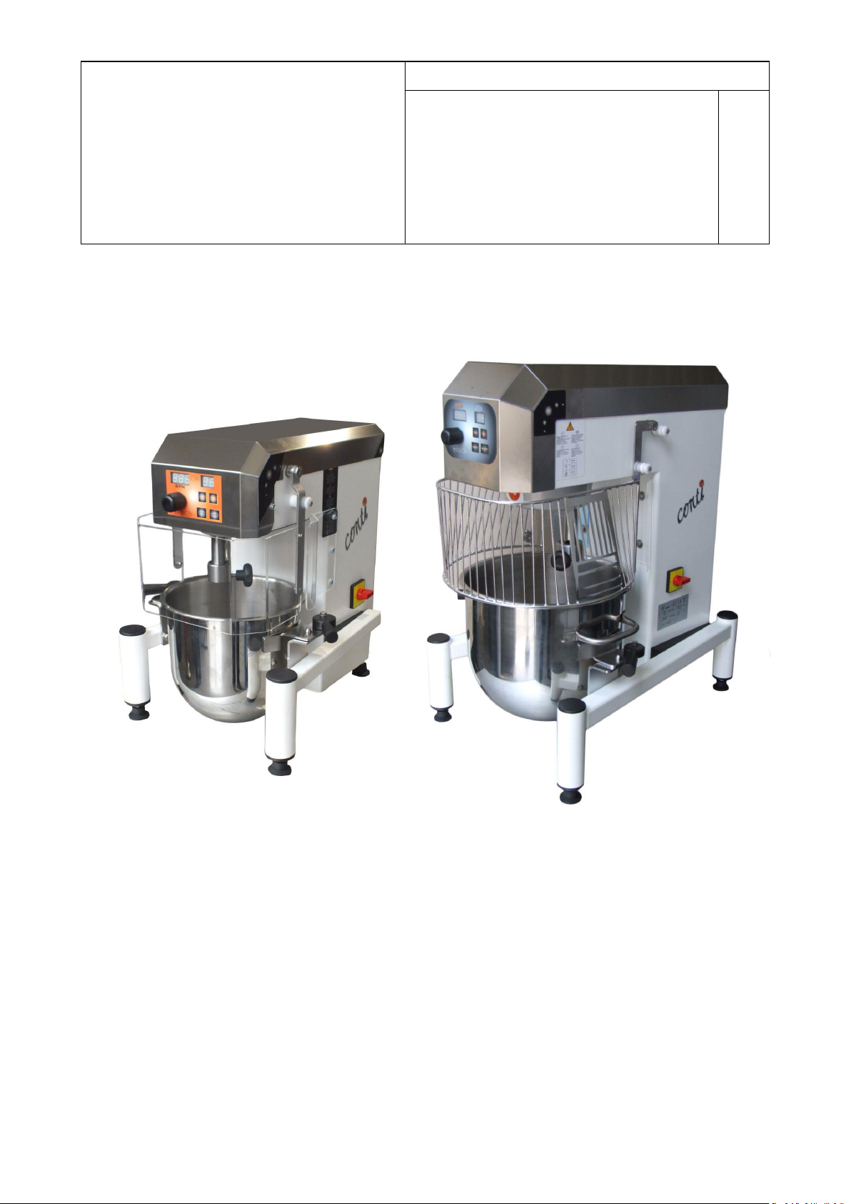
LT 5 – 8 – 10 – 20
MANUALE DI ISTRUZIONI
INSTRUCTION MANUAL
MODE D'EMPLOI
MANUAL DE INSTRUCCIONES
REV.
03
VARIATORE DIGITALE
ELECTRONIC SPEED VARIATOR
VARIATEUR DIGITAL DE VITESSE
VARIADOR ELECTRONICO
Lt 5
Lt 8
Lt 10
Lt 20
MESCOLATRICE PLANETARIA DA BANCO
BATTEUR MELANGEUR DA TABLE / BATIDORA DE MESA
BENCH PLANETARY MIXER
Page 2
Printed on 60 gr. ecological paper, 25% less natural ressources used.
Page 3
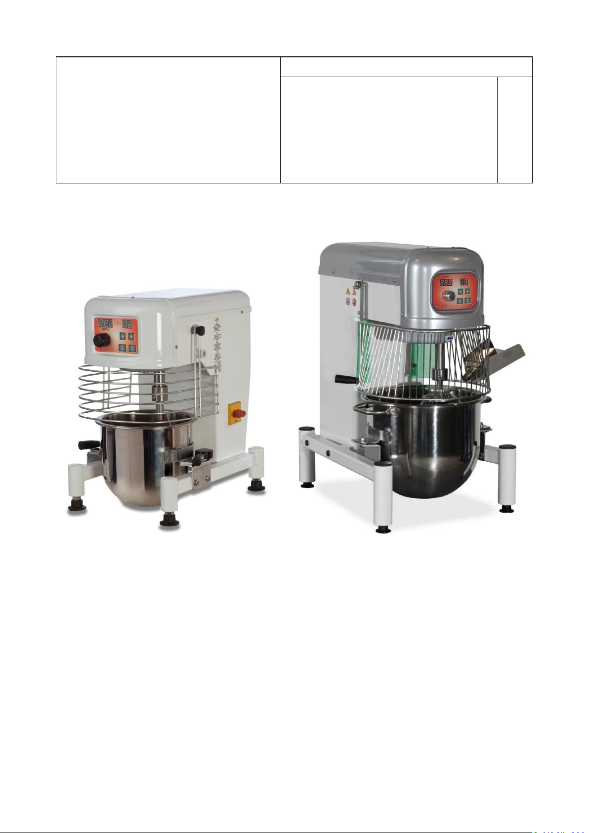
LT 5 – 8 – 10 – 20
MANUALE DI ISTRUZIONI
INSTRUCTION MANUAL
MODE D'EMPLOI
MANUAL DE INSTRUCCIONES
REV.
03
VARIATORE DIGITALE
ELECTRONIC SPEED VARIATOR
VARIATEUR DIGITAL DE VITESSE
VARIADOR ELECTRONICO
Lt 5
Lt 8
Lt 10
Lt 20
MESCOLATRICE PLANETARIA DA BANCO
BATTEUR MELANGEUR DA TABLE / BATIDORA DE MESA
BENCH PLANETARY MIXER
Page 4

ITALIANO
INDICE / INDEX / SOMMAIRE / CONTENIDO
MARCATURA DELLA MACCHINA ................................................................................................................................................................9
INFORMAZIONI GENERALI .........................................................................................................................................................................9
USO PREVISTO DELLA MACCHINA ............................................................................................................................................................10
DESCRIZIONE TECNICA .............................................................................................................................................................................10
DISPOSITIVI DI SICUREZZA........................................................................................................................................................................11
DESCRIZIONE DEI COMANDI ....................................................................................................................................................................11
CONDIZIONI AMBIENTALI ........................................................................................................................................................................12
TRASPORTO E POSIZIONAMENTO ............................................................................................................................................................12
INSTALLAZIONE ........................................................................................................................................................................................12
USO DELLA MACCHINA ............................................................................................................................................................................13
PULIZIA DELLA MACCHINA .......................................................................................................................................................................14
POSSIBILI AVARIE E/O ANOMALIE ............................................................................................................................................................15
MESSA FUORI SERVIZIO ...........................................................................................................................................................................15
SMANTELLAMENTO .................................................................................................................................................................................15
MACHINE MARKING .................................................................................................................................................................................16
GENERAL INFORMATION .........................................................................................................................................................................16
INTENDED USE OF THE MACHINE ............................................................................................................................................................17
TECHNICAL DESCRIPTION .........................................................................................................................................................................17
SAFETY DEVICES .......................................................................................................................................................................................18
DESCRIPTION OF COMMANDS .................................................................................................................................................................18
ENVIRONMENTAL CONDITIONS ...............................................................................................................................................................19
TRANSPORT AND POSITIONING ...............................................................................................................................................................19
INSTALLATION ..........................................................................................................................................................................................19
USING THE MACHINE ...............................................................................................................................................................................20
CLEANING THE MACHINE .........................................................................................................................................................................21
TROUBLE-SHOOTING ...............................................................................................................................................................................22
DECOMMISSIONING ................................................................................................................................................................................22
DISMANTLING AND DISPOSAL .................................................................................................................................................................22
MARQUAGE DE LA MACHINE ...................................................................................................................................................................23
INFORMATIONS GÉNÉRALES ....................................................................................................................................................................23
UTILISATION PRÉVUE DE LA MACHINE ....................................................................................................................................................24
DESCRIPTION TECHNIQUE ........................................................................................................................................................................24
DISPOSITIFS DE SÉCURITÉ ........................................................................................................................................................................25
DESCRIPTION DES COMMANDES .............................................................................................................................................................25
CONDITIONS ENVIRONNEMENTALES.......................................................................................................................................................26
TRANSPORT ET MISE EN PLACE ................................................................................................................................................................26
INSTALLATION ..........................................................................................................................................................................................26
UTILISATION DE LA MACHINE ..................................................................................................................................................................27
NETTOYAGE DE LA MACHINE ...................................................................................................................................................................28
PANNES ET/OU ANOMALIES POSSIBLES ..................................................................................................................................................29
MISE HORS SERVICE .................................................................................................................................................................................29
MISE AU REBUT ........................................................................................................................................................................................29
MARCADO DE LA MÁQUINA ....................................................................................................................................................................30
INFORMACIÓN GENERAL .........................................................................................................................................................................30
USO PREVISTO DE LA MÁQUINA ..............................................................................................................................................................31
DESCRIPCIÓN TÉCNICA .............................................................................................................................................................................31
DISPOSITIVOS DE SEGURIDAD ..................................................................................................................................................................32
DESCRIPCIÓN DE LOS MANDOS ...............................................................................................................................................................32
CONDICIONES AMBIENTALES ...................................................................................................................................................................33
TRANSPORTE E INSTALACIÓN ..................................................................................................................................................................33
INSTALACIÓN ...........................................................................................................................................................................................33
USO DE LA MÁQUINA ..............................................................................................................................................................................34
LIMPIEZA DE LA MÁQUINA ......................................................................................................................................................................35
POSIBLES AVERÍAS Y/O ANOMALÍAS ........................................................................................................................................................36
PUESTA FUERA DE SERVICIO ...................................................................................................................................................................36
DESMANTELAMIENTO..............................................................................................................................................................................36
RICAMBI / SPARE PARTS ..........................................................................................................................................................................37
4
Page 5
ITALIANO
FIG. 1
FIG. 2
5
Page 6
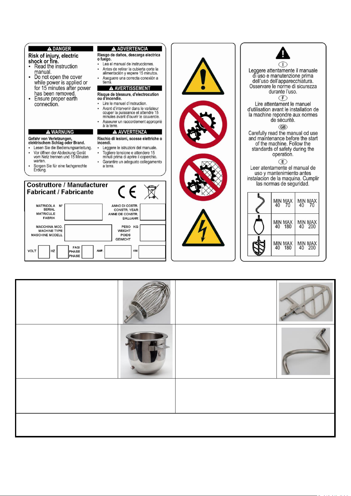
SIMBOLOGIE / SYMBOLS / SYMBOLES / SÍMBOLOS
N° 1 Frusta a fili fini
N° 1 Thin wire whisk
N° 1 Fouet
N° 1 Batidor de hilos finos
N° 1 Spatola
N°.1 Spatula
N°.1 Spatula
N° 1 Espátula
Vasca refrigerata *
Chilled tank *
Cuve réfrigérée *
Cuba refrigerada *
N°1 Spirale
N°1 Spiral tool
N° 1 Crochet a spiral
N° 1 Util de espiral
Riduzione lt. 10 (vasca + 3 utensili) **
Reduction 10 lt. (tank + 3 tools) **
Réduction 10 Litres (cuve + 3 ustensiles) **
Reducción 10 litros (cuba + 3 herramientas) **
Piedistallo di cm 40 **
Pedestal 40 cm **
Socle de 40 cm **
Pedestal de 40 cm **
* (Solo a richiesta) (Optional) (Option) (Opción)
** (solo a richiesta LT. 20) (Optional) (Option) (Opción)
ITALIANO
FIG. 3
FIG. 4
6
Page 7

ITALIANO
APPLICATIONS
COMPOSANTS
Lt 5
Lt 8
Lt 10
Lt 20
SPEEDS
VAR
R.P.M.
Pane - Bread
Pains - Pain
Kg. di farina
con 50% d’acqua
Kg. of flour
Kg. de herina
Kg. de farine
0,2 / 1,1
0,4 / 1,8
0,4 / 2,0
1 / 4,5
40 / 60
Pizza
Patè a pizza
Kg. di farina
con 50% d’acqua
Kg. of flour
Kg. de herina
Kg. de farine
0,2 / 1,1
0,4 / 1,8
0,4 / 2,0
1 / 4,5
40 / 60
Croissants
Kg. di farina
con 50% d’acqua
Kg. of flour
Kg. de herina
Kg. de farine
0,2 / 1,1
0,4 / 1,8
0,4 / 2,0
1 / 4,5
40 / 80
Brioche
Kg. di farina
con 50% d’acqua
Kg. of flour
Kg. de herina
Kg. de farine
0,2 / 1,3
0,4 / 2
0,4 / 2,4
1 / 5
40 / 80
Albume Albumen
Blancs
Numero di uova
Number of eggs
Nombre d’oeufs
Numero de huevos
2 / 7
4 / 12
6 / 15
10 / 30
150 / 200
Meringa
Meringue
Kg. di zucchero
Kg. of sugar
Kg. de sucre
Kg. de azucar
0,1 / 0,3
0,2 / 0,7
0,3 / 0,9
0,5 / 1,5
100 / 200
Biscotti
Biscuits
Numero di uova
Number of eggs
Nombre d’oeufs
Numero de huevos
2 / 7
4 / 12
5 / 15
10 /30
140 / 200
Pan di spagna
Sponge cake
Genoise
Numero di uova
Number of eggs
Nombre d’oeufs
Numero de huevos
2 / 7
4 / 12
5 / 15
10 /30
150 / 200
Pasta all’uovo
Italian fresh pasta
Italian pates fraiches
Pasta italiana de huevo fresco
Kg. di farina
con 50% d’acqua
Kg. of flour
Kg. de herina
Kg. de farine
0,1 / 0,5
0,1 / 0,7
0,1 / 0,8
0,2 / 1,6
40 / 60
FIG. 5
7
Page 8

ITALIANO
MODELLO / MODEL / MODÈLE / MODELO
Lt 5
Lt 8
Lt 10
Lt 20
PESO / WEIGH
POIDS / PESO
kg
25 Kg
32 Kg
34 Kg
50 Kg
TENSIONE
VOLTAGE
VOLTAGE
VOLTAJE
V
220 / 400(*)
220 / 400(*)
220 / 400(*)
220 / 400(*)
FREQUENZA
FREQUENCY
FRÉQUENCE
FRECUENCIA
Hz
50
50
50
50
FASI / PHASES
PHASÉ / FASI
N°
2f / 3f(*)
2f / 3f(*)
2f / 3f(*)
2f / 3f(*)
POTENZA
POWER
PUISSANCE
POTENCIA
A
1,58
1,9
1,9
3,08
Kw
0,25
0,37
0,37
0,75
ALTEZZA
HEIGHT
HAUTEUR
ALTURA
mm
465
616
660
800
LARGHEZZA
WIDTH
LARGEUR
ANCHO
mm
330
380
380
500
LUNGHEZZA
LENGTH
LONGUEUR
LONGITUD
mm
400
480
480
650
VELOCITÀ
SPEED
VITESSE
VELOCITAD
rpm
1400
1400
1400
1400
RUMORE
NOISE EMISSION
BRUIT ÉMIS
RUIDO EMITIDO
Inferiore a 70 dB / Less than 70 dB / Moins que 70 dB / Inferior al 70 dB
FIG. 6
8
Page 9

ITALIANO
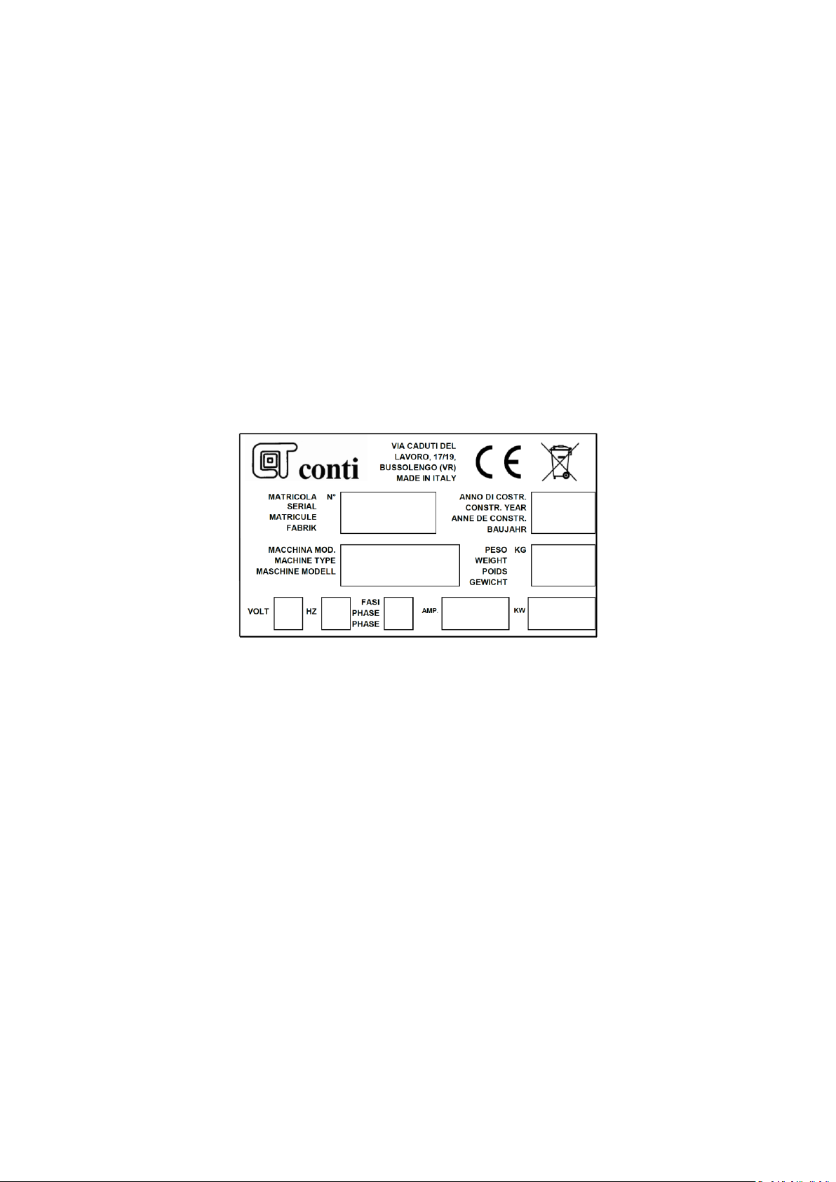
Dati del Costruttore
Marcatura CE
Simbolo RAEE
Numero di Matricola
Anno di costruzione
Modello della macchina
Peso (Kg)
Voltaggio (Volt)
Frequenza di alimentazione (HZ)
Numero Fasi
Corrente assorbita (AMP.)
Potenza assorbita (KW)
ATTENZIONE: La bacinella può risultare pesante in fase di movimentazione manuale. L’operazione
deve essere effettuata da 2 operatori se il peso dell’impasto supera i 20 Kg.
ATTENZIONE: Manipolare con estrema cura i prodotti in polvere (farina, cacao ecc.) svuotarli dalla
confezione nella parte inferiore della vasca evitando possibili dispersioni. Se necessario utilizzare
appositi dispositivi di protezione delle vie respiratorie durante il carico manuale degli ingredienti in
polvere.
Gli organi in movimento della macchina sono schermati da barriere fisiche.
Si fa assoluto divieto rimuovere o modificare le suddette barriere.
È assolutamente vietato compiere azioni sulla macchina se queste non sono previste nel presente
manuale.
MARCATURA DELLA MACCHINA
Ogni macchina è dotata di una targhetta che riporta le caratteristiche essenziali della macchina.
In particolare, essa fornisce le seguenti informazioni, con riferimento alla FIG. 3:
INFORMAZIONI GENERALI
Il manuale di istruzioni è da considerare parte integrante della macchina e deve essere conservato per futuri
riferimenti fino al termine della vita della macchina.
Prima di effettuare qualsiasi operazione con la macchina leggere attentamente il presente libretto di istruzioni
ed in particolare il capitolo sulla sicurezza.
Il manuale deve essere conservato in modo da poter essere sempre disponibile alla lettura ed in modo da non
essere danneggiato (luogo protetto da agenti esterni, umidità, polveri, raggi solari, ecc..)
Il fabbricante ha il diritto di aggiornare la produzione ed i manuali di istruzione senza l'obbligo di aggiornare
produzione e manuali precedenti.
Il fabbricante si ritiene sollevato da qualsiasi responsabilità derivante da:
- Uso improprio, erroneo od irragionevole della macchina.
- Uso contrario alle normative nazionali vigenti.
- Installazione scorretta della macchina.
- Difetti di alimentazione.
- Carenze nella manutenzione prevista.
- Modifiche od interventi non autorizzati.
- Uso di ricambi e prodotti non originali o specifici per il modello.
- Inosservanza delle istruzioni.
All'arrivo della macchina, dopo aver tolto l'imballaggio, assicurarsi dell'integrità della macchina.
In caso di dubbio rivolgersi a personale qualificato.
SITUAZIONI DI PERICOLO
La macchina presenta pericoli quali: parti in movimento e presenza di tensione. I criteri con cui la stessa è
stata progettata e costruita hanno permesso di abbassare molto il livello di rischio, per renderlo praticamente
nullo si devono seguire in modo inderogabile le prescrizioni del presente manuale.
I rischi residui che non si sono potuti eliminare a causa delle caratteristiche di lavoro della macchina e che
bisogna assolutamente tenere sempre presenti per poterli evitare sono:
9
Page 10

ITALIANO
USO PREVISTO DELLA MACCHINA
USO CORRETTO DELLA MACCHINA
La macchina è destinata all'uso da parte di personale qualificato alla produzione ed alla manipolazione di
farine e paste, tra cui in particolare i laboratori di pasticceria e panificazione.
La presente macchina è una macchina impastatrice planetaria: serve, cioè, ad impastare e mescolare qualsiasi
tipo di impasto per pasticceria (creme, panna, pasta, ecc..). L'effetto di impasto è ottenuto tramite l'uso di
utensili intercambiabili forniti di serie che agiscono ruotando in modo planetario ed hanno diverse forme e di
conseguenza diverse modalità di impiego.
POTENZIALITÀ DELLA MACCHINA
Il motore e la trasmissione ad ingranaggi a bagno d’olio permettono una potenzialità massima della macchina
con la possibilità di lavorare anche a vasca piena per mescolare.
Se invece si tratta di fare impasti per pane, pizza o simile è necessario non superare mai 1/3 (un terzo) della
capacità della vasca e con un rapporto di acqua/farina del 50 %.
Rispettare in ogni caso i dati indicati nella tabella DOSI CONSIGLIATE FIG. 5.
USO SCORRETTO DELLA MACCHINA
La macchina è stata progettata solo per l'uso previsto descritto nei paragrafi precedenti.
Ogni altro uso può provocare danni alla macchina e/o condurre a situazioni di pericolo di cui il fabbricante non
può essere ritenuto responsabile.
In particolare non è consentito lavorare altri tipi di materiali (alimentari o meno) che non corrispondano ai
requisiti sopra descritti.
DESCRIZIONE TECNICA
Tutti i dati tecnici sono indicati nella tabella FIG. 6.
SCOPO
Mescola, sbatte e amalgama ingredienti al fine di ottenere impasti per pasticceria e piccoli impasti per
panificazione.
CICLO DI LAVORO
Carico ingredienti: Effettuato manualmente dall’operatore che introduce gli ingredienti nella bacinella.
Scarico impasto: Effettuato manualmente dall’operatore che preleva la bacinella e deposita l’impasto in
apposito sito.
Conduzione: Le operazioni affidate al personale durante il normale uso della macchina sono: messa in
servizio, regolazione, carico, scarico ed arresto su un processo che può essere automatico o manuale.
COSTRUZIONE
Struttura portante: Sostiene tutte le parti che concorrono alla lavorazione dell’impasto.
Motorizzazione: Fornisce tramite accoppiamento cinghia, pulegge e ingranaggi a grasso, il moto rotatorio al
gruppo di mescolazione.
Gruppo di mescolazione: Insieme delle parti di contenimento e di mescolazione direttamente coinvolte nella
lavorazione dell’impasto.
Supporto bacinella: Sistema di sostegno e posizionamento della bacinella, per le operazioni di carico scarico
degli ingredienti.
Impianto elettrico: Quadro principale di derivazione e distribuzione energia elettrica.
Quadro comandi: Quadro di controllo, impostazione e comando della produzione.
10
Page 11

ITALIANO
PULSANTE DI EMERGENZA
Pulsante a fungo rosso su base gialla interrompe il
funzionamento della macchina in caso di emergenza
PROTEZIONI FISSE ANTI INTRUSIONE
Struttura che impedisce di avvicinarsi alle parti pericolose
MICROINTERRUTTORE PRESENZA BACINELLA
Consente l’avviamento della macchina solo se la bacinella è
montata e posizionata correttamente
MICROINTERRUTTORI DI SICUREZZA
Arrestano la macchina in caso di apertura della protezione
durante il funzionamento
PIEDINI ANTIVIBRANTI
Riducono il passaggio delle vibrazioni al terreno
È ASSOLUTAMENTE VIETATO inibire e/o modificare i dispositivi e le funzioni di sicurezza.
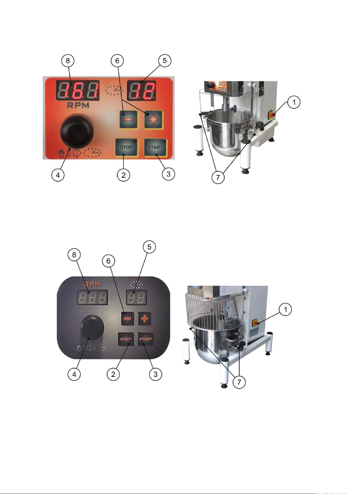
N°
Descrizione
Attuatore
Colore
1
Interruttore generale
interruttore
Giallo rosso
2
Stop del motore
Pulsante
3 Avviamento del motore
Pulsante
4 Regolatore velocità
Volantino-Manopola
Attivatore timer
Pulsante
5 Timer digitale 0-99 minuti
Display Lcd
6 Impostazione temporizzatore
2 pulsanti
7 Blocco bacinella
Supporto
8 Display Rpm Velocità utensile
Schermo LCD
FUNZIONAMENTO
Introduzione degli ingredienti: Avviene manualmente da parte dell’operatore che introduce nella bacinella gli
ingredienti.
Ciclo di lavorazione: Gli ingredienti vengono mescolati per un tempo predefinito per mezzo di un accessorio
intercambiabile a seconda dell’impasto che si vuole ottenere.
Scarico impasto: Effettuato manualmente dall’operatore che preleva la bacinella dal supporto della macchina
e scarica il contenuto in un luogo appositamente predisposto.
ACCESSORI
Gli accessori disponibili per la macchina sono visibili nella tabella FIG. 4.
DISPOSITIVI DI SICUREZZA
DESCRIZIONE DEI COMANDI
MODELLO CON VARIATORE DIGITALE
Per la descrizione fare riferimento alla FIG. 2.
11
Page 12

ITALIANO
CONDIZIONI AMBIENTALI
TEMPERATURA min. -5°C max. 40°C
UMIDITÀ RELATIVA max. 50% a 40°C
ALTITUDINE max. 1000 m.
REQUISITI DEL LUOGO DI LAVORO
AMBIENTE:
Non esplosivo.
Non corrosivo.
Non deve presentare repentini sbalzi di temperatura.
Al riparo da intemperie e dal contatto diretto con l’acqua.
ILLUMINAZIONE:
Diffusa, non deve creare coni d’ombra all’esterno della macchina, non deve creare fenomeni di
abbaglio o stroboscopici.
PIANO DI APPOGGIO:
Piano orizzontale e liscio.
Deve sostenere un peso, secondo il modello (vedere la tabella FIG. 6) oltre ai carichi già esistenti.
ALLACCIAMENTI ELETTRICO:
Tensione di alimentazione 230/400 V, 50 Hz con una variazione massima del ± 10% per quanto riguarda la
tensione e del ± 1% per la frequenza.
La linea di alimentazione deve essere dimensionata per una corrente nominale secondo il modello (vedere la
tabella FIG. 6), protetta contro i sovraccarichi, cortocircuiti ed i contatti indiretti (differenziale + conduttore di
protezione) ed avente una caduta di tensione pari al ± 1% della tensione di rete.
N.B. prendere visione documentazione tecnica elettrica allegata.
TRASPORTO E POSIZIONAMENTO
La macchina è spedita in collo unico, completamente montata. Per la spedizione dalla casa costruttrice, la
macchina è collocata e fermata su pallet e, se necessario o contrattualmente previsto, in un imballaggio di
cartone di grosso spessore (scatolone) o legno (gabbia). Nel movimentare/trasportare la macchina adottare
ogni precauzione per evitare, o limitare, l’insorgere di rischi per persone o cose.
Il carico/scarico sul/dal mezzo di trasporto viene di norma effettuato per mezzo di un carrello elevatore /
transpallet di portata adeguata (vedere la tabella FIG. 6) i cui bracci vanno inseriti negli appositi spazi alla base
del pallet.
INSTALLAZIONE
1) Aprire la cassa in legno utilizzata per il trasporto (se presente).
2) Scoprire la macchina dal nylon protettivo.
3) Liberare la macchina dall’ancoraggio al pallet.
4) Sollevare la macchina con fune di sollevamento con presa sotto la testa e depositarla nel luogo di
installazione.
5) Garantire una distanza minima di 30 cm. da qualsiasi macchina o muro.
6) Assicurarsi che la macchina abbia una perfetta aderenza al pavimento regolando eventualmente i 4 dadi
sotto il basamento per ancoraggio definitivo a terra dei piedini stabilizzatori.
7) Allacciare la spina di alimentazione dell’impianto elettrico alla presa comandata predisposta
dall’acquirente.
12
Page 13

ITALIANO
8) Verificare il corretto senso di rotazione dell’utensile (vedere l’apposita freccia) in caso ruotasse in senso
contrario, arrestare immediatamente la macchina e procedere all’inversione di una fase della spina di
alimentazione (esclusivamente personale specializzato).
9) Separare i materiali per tipologia (cartone, plastica, legno, ecc.) e collocarli in appositi luoghi di raccolta,
accessibili solo a persone autorizzate, in attesa che vengano smaltiti da ditte specializzate. Anche i
travetti di legno e il pallet vanno portati in luogo di raccolta appositamente destinato.
USO DELLA MACCHINA
Il funzionamento della macchina avviene nel seguente modo:
PREPARAZIONE
1) Inserire la spina nella presa di corrente di rete.
2) Dare tensione alla macchina agendo sull’interruttore generale 1.
3) Aprire la protezione di accesso della zona del mescolatore.
4) Sollevare il manicotto di blocco degli accessori.
5) Sfilare l’accessorio presente e sostituirlo con quello desiderato.
6) Abbassare il manicotto avendo cura di inserire il grano posteriore nell’asola del manicotto.
7) Chiudere la protezione.
8) Leggere attentamente le indicazioni riportate sulla targhetta FIG. 3.
9) Procedere con la lavorazione oppure agire sull’interruttore generale 1 per arrestare la macchina.
10) Sfilare la spina dell’impianto elettrico dalla presa (se necessario).
FASI DI LAVORO FIG. 2
L’operatore controlla a vista il ciclo di lavoro e interviene in prima persona all’arresto della lavorazione.
1) Inserire la spina nella presa di corrente di rete.
2) Dare tensione alla macchina agendo sull’interruttore generale 1.
3) Aprire la protezione di accesso della zona del mescolatore.
4) Inserire gli ingredienti nella bacinella.
5) Chiudere la protezione a rete.
6) Attivate il temporizzatore premendo la manopola N.4.
7) Impostare il temporizzatore per i minuti desiderati ( da 0 a 99) , oppure premere la manopola N.4 per
escludere l’utilizzo del temporizzatore.
8) Avviare la lavorazione premendo il pulsante N.3 di avviamento motore
9) Agire, secondo esperienza acquisita, sulla manopola N.4 per regolare la velocità:
- Da un minimo di 40 giri per minuto (verso sinistra)
- A un massimo di 200 giri per minuto (verso destra)
10) Iniziare la lavorazione.
11) Al termine della lavorazione premere il pulsante N° 2 per arrestare il ciclo.
(oppure attendere la fine del tempo impostato – il timer, se interrotto per una pausa, ha la memoria del
tempo trascorso e ripartirà finendo solo il tempo mancante )
12) Aprire la protezione.
13) Togliere l’accessorio di mescolazione.
14) Sollevare la vasca dai 2 fermi laterali (7) per estrarla.
15) Prelevare la bacinella e vuotare il contenuto in un recipiente predisposto.
16) Pulire adeguatamente la bacinella e tutte le parti a contatto con il materiale lavorato.
17) Posizionare la bacinella e bloccarla nei due pioli (7).
18) Se si intende riprendere la lavorazione tornare alla fase N° 5 oppure proseguire.
19) Chiudere la protezione.
20) Agire sull’interruttore generale 1 per disalimentare la macchina.
21) Togliere la spina di alimentazione impianto elettrico.
13
Page 14

ITALIANO
Pericolo: per motivi di sicurezza tutte le operazioni di pulizia vanno fatte a macchina ferma e
sezionata dalla rete elettrica di alimentazione.
PULIZIA DELLA MACCHINA
La vasca, la protezione rotante antinfortunistica e l’utensile sono totalmente rimovibili dalla macchina in
modo da potere essere puliti.
ATTENZIONE: Gli utensili in alluminio vanno puliti esclusivamente con acqua per evitare l'ossidazione degli
stessi.
IMPORTANZA DELLA PULIZIA
La corretta e puntuale pulizia della macchina, oltre a contribuire a mantenerla in condizioni di efficienza, è di
fondamentale importanza. Infatti la mancanza di igiene è causa di rischi alla salute umana e di alterazione
inaccettabile del prodotto alimentare.
Pertanto si raccomanda all'utilizzatore di osservare scrupolosamente le istruzioni per la pulizia riparlate nel
seguito, usando esclusivamente i prodotti indicati in modo da non recare danni alle diverse parli della
macchina. La macchina deve essere pulita al termine di ogni turno di lavoro.
PRODOTTI PER LA PULIZIA
Per la pulizia della macchina, escluse le parti interne, usare detergente di tipo biodegradabile privo di fosforo
e cloruri. In particolare, per la pulizia di vasche, bacinelle e contenitori in acciaio inox, si consiglia di usare
esclusivamente detergente biodegradabile per stoviglie e lavastoviglie a pH neutro.
ISTRUZIONI PER LA PULIZIA
AVVERTENZE GENERALI RIGUARDO PULIZIA E LAVAGGIO
NON USARE detergenti contenenti prodotti chimici aggressivi, irritanti e non biodegradabili.
NON USARE getti d'acqua o idropulitrici.
NON USARE detergenti contenenti trielina o clorotene.
NON USARE getti di aria compressa, poiché generando polvere nuocciono alla vostre salute, si consiglia
l'uso di un aspirapolvere.
NON USARE per la pulizia acqua a temperatura superiore a 60 °C, soluzioni a base di soda caustica,
acido cloridrico o acido solforico, poiché dannosi per le superfici.
14
Page 15
ITALIANO
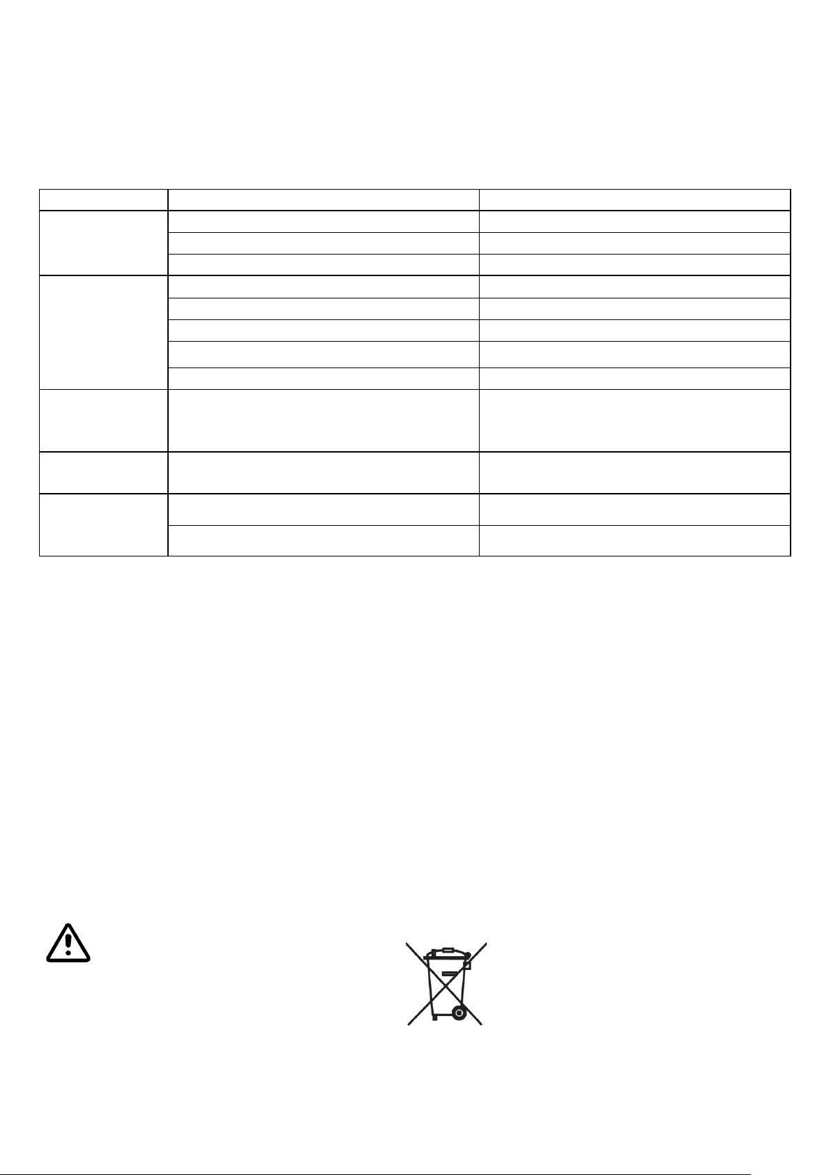
ANOMALIA
CAUSA
RIMEDIO
La macchina non
si avvia
Spina di alimentazione disinserita
Inserire la spina
Interruttore generale disinserito
Inserire l’interruttore generale
Presenza piolo sensore vasca mancante
Sostituire con uno nuovo
Premendo il
pulsante di
marcia
l’accessorio non
ruota
Vedi cause precedenti
Inserire la spina e l’interruttore generale
Protezione aperta
Chiudere il riparo antinfortunistico
Pulsante di emergenza premuto
Sbloccare il pulsante di emergenza
Bacinella non collocata sul supporto
Collocare la bacinella sul supporto
Bacinella non in posizione di lavoro (alta)
Portare la bacinella in posizione di lavoro
L’accessorio
ruota in senso
antiorario
Le fasi della macchina non corrispondono
alla linea di alimentazione
Interpellare elettricista professionale per
procedere a scambio fili delle fasi sulla spina
elettrica di connessione
Perdita di giri
dell’accessorio
Cinghie di trasmissione allentate od usurate
Tendere le cinghie o sostituirle
Rotazione
irregolare
dell’accessorio
Cinghia di trasmissione allentata od usurata
Tendere la cinghia o sostituirla
Pignone dell’eccentrico danneggiato
Sostituire il pignone
Adottare si devono seguire le prescrizioni delle leggi vigenti alla data di smaltimento.
Il simbolo apposto sull’apparecchiatura, e qui mostrato, indica che essa non deve essere smaltita
come normale rifiuto urbano, ma deve essere conferita separatamente ad un centro di raccolta
RAEE specificatamente predisposto per il trattamento conforme degli apparati elettrici e/o
elettronici. Riferimento Direttiva 2002/96/CE del Parlamento Europeo e del consiglio del 27/01/03
sui rifiuti da apparecchiature elettriche ed elettroniche.
Lo smaltimento non corretto o un uso improprio dell’apparecchiatura o di parti di essa, potrebbe
produrre effetti potenzialmente negativi e dannosi per l’ambiente e la salute delle persone.
POSSIBILI AVARIE E/O ANOMALIE
La seguente tabella indica:
La descrizione del problema ovvero i sintomi di mal funzionamento più probabili.
La o le cause possibili di danno.
I correttivi proposti.
MESSA FUORI SERVIZIO
Arrestare il ciclo di lavoro della macchina.
Interrompere l’erogazione dell’energia elettrica ruotando l’interruttore generale n°1 nella posizione 0.
Sfilare spina di alimentazione impianto elettrico.
Spostare la macchina in un luogo di deposito.
Coprire la macchina con un nylon.
Apporre un cartello riportante la scritta “Fuori servizio”
SMANTELLAMENTO
Nessun elemento della macchina deve essere disperso nell’ambiente.
Ogni parte, componente o gruppo di componenti deve essere raggruppato secondo tipologia di materiale.
15
Page 16

ENGLISH
Manufacturer’s Information
EC Marking
WEEE Symbol
Serial Number
Year of construction
Machine Model
Weight (kg)
Voltage
Power supply frequency (Hz)
Number of Phases
Electric current requirement (Amp)
Power consumption (kW)
WARNING: The bowl may be heavy while handling manually. The operation must be carried out by
2 operators if the weight of the dough exceeds 20 kg.
WARNING: Handle powders (flour, cocoa, etc.) with extreme care. Empty them from the top of the
package into the lower part of the tank, avoiding potential dispersions. If necessary, use special
protection devices for airways during manual loading of powdered ingredients.
The moving parts of the machine are protected by physical barriers.
It is absolutely prohibited to remove or modify these barriers.
It is absolutely prohibited to take any action on the machine if it is not specified in this manual.
MACHINE MARKING
Every machine has a plate indicating its essential characteristics.
In particular, it provides the following information, with reference to FIG.4:
GENERAL INFORMATION
The instruction manual is to be considered an integral part of the machine and must be kept for future
reference until the end of the life of the machine.
Before carrying out any operation with the machine, read this instruction booklet very carefully, especially the
chapter on safety.
The manual must be kept in such a way that it is always available to be read and cannot be damaged (a place
protected against external agents, humidity, dust, sunlight, etc. ).
The manufacturer has the right to update products and the manual with no obligation to update previous
products and manuals.
The manufacturing company holds itself exempt from any and all responsibility deriving from:
- The inappropriate, erroneous, or unreasonable use of the machine.
- Use not in conformity with current national laws and regulations.
- Incorrect installation of the machine.
- Power supply defects.
- Failure to carry out programmed maintenance.
- Unauthorised modifications or interventions.
- Use of non-original or specific replacement parts and products for the model.
- Failure to follow the instructions.
Upon arrival of the machine, after having removed the packaging, check the integrity of the machine.
In case of doubt, contact qualified personnel.
DANGEROUS SITUATIONS
The machine presents dangers like: moving parts and live voltage. The criteria with which the machine was
designed and constructed have made it possible to lower the risk level considerably; read this manual
carefully and strictly follow the instructions to minimize the risk as far as possible.
The residual risks that were not possible to eliminate due to the operational characteristics of the machine
and that must absolutely be taken into account in order to avoid them are:
16
Page 17

ENGLISH
INTENDED USE OF THE MACHINE
CORRECT USE OF THE MACHINE
The machine is intended to be used by qualified personnel for the production and handling of flours and
doughs, more specifically in pastry and baking workshops.
This machine is a planetary dough mixer: It is used to knead and mix any type of dough for making pastries
(cream fillings, cream, dough, etc.). The mixing is obtained by using the interchangeable tools provided with
the machine with planetary rotational movement. These tools have different shapes and, hence, are used for
different purposes.
MACHINE PERFORMANCE
The oil-bath geared motor enables a maximum power of the machine with the possibility of mixing even when
the tank is full.
Instead, for making doughs for bread, pizza, or something similar, the level of 1/3 (one third) of the capacity of
the tank must never be exceeded and the dough must have a water/flour ratio of 50%.
In any case, respect the data indicated in the RECOMMENDED DOSES table in FIG. 5.
INCORRECT USE OF THE MACHINE
The machine was designed only for the intended uses described in the previous paragraphs.
Any other use may cause damage to the machine and/or lead to a dangerous situation for which the
manufacturer cannot be held responsible.
In particular, it is not allowed to work with other types of materials (food or otherwise) that do not
correspond to the requirements described above.
TECHNICAL DESCRIPTION
All the technical data are indicated in the table in FIG. 6.
PURPOSE
Mixing, beating, and amalgamating ingredients in order to obtain doughs for pastries and small batches of
bread dough.
WORK CYCLE
Loading ingredients: Loaded manually by the operator, who introduces the ingredients into the bowl.
Unloading dough: Unloaded manually by the operator who removes the bowl and deposits the dough in a
specific place.
Operation: Operations entrusted to personnel during normal use of the machine are: starting up, regulation,
loading, unloading and stopping of a process that can be either manual or automatic.
CONSTRUCTION
Support structure: Supports all the parts that work together to process the dough.
Motorization: The machine is driven by an assembly consisting of belts and oil-bathed gears and pulleys,
which conveys the rotatory motion to the mixing unit.
Mixing unit: The set of containment and mixing parts directly involved in processing the dough.
Bowl support: Support and positioning system of the bowl, with loading/unloading the ingredients.
Electrical system: Electrical energy main switchboard and distribution panel.
Control panel: Control, setting, and production control panel.
17
Page 18
ENGLISH
EMERGENCY BUTTON
A red mushroom-shaped button on a yellow base interrupts
the operation of the machine in case of an emergency.
FIXED ANTI-INTRUSION GUARDS
A structure that prevents people from going near dangerous
parts.
BOWL PRESENCE MICRO-SWITCH
Enables start-up of the machine only if the bowl is
assembled and positioned correctly.
SAFETY MICRO-SWITCHES
These stop the machine if the protection is opened during
operation.
ANTI-VIBRATING FEET
Reduce the passage of vibrations to the ground.
IT IS ABSOLUTELY PROHIBITED to disable and/or modify safety devices and functions.
Pos.
Description
Actuator
Colour
1
Mains switch
Switch
Red and yellow
2
Emergency button
Button
Red on yellow background
3
Timer display
LCD Screen
4 Speed regulator
Flywheel-handle
Timer Activator
Button
5 Start/Stop motor
2 buttons
6 Block bowl
supports
7 Timer setter
2 buttons
8 Tool RPM speed display
LCD Screen
OPERATION
Introducing the ingredients: The operator introduces the ingredients manually into the bowl.
Work cycle: The ingredients are mixed for a predefined time by interchangeable accessories, depending on
the dough desired.
Unloading dough: The operator unloads the dough manually by removing the bowl from the support of the
machine and unloading the contents into a specifically assigned place.
ACCESSORIES
The accessories available for the machine are visible in the table in FIG. 4.
SAFETY DEVICES
DESCRIPTION OF COMMANDS
MODEL WITH DIGITAL VARIATOR
For the description, see FIG. 2.
18
Page 19

ENGLISH
ENVIRONMENTAL CONDITIONS
TEMPERATURE: min. -5°C max. 40°C
RELATIVE HUMIDITY max. 50% at 40°C
ALTITUDE max. 1000 m.
WORKPLACE REQUIREMENTS
ENVIRONMENT:
Non-explosive.
Non-corrosive.
There must be no sudden changes in temperature.
Protected from atmospheric agents and from direct contact with water.
LIGHTING:
Diffused, as it must not create cones of shadows on the outside of the machine or create blinding
flashes or stroboscopic effects.
SUPPORT SURFACE:
Horizontal and smooth
It must support the weight of the model at hand (see the table in FIG. 6) in addition to previously
existing loads.
ELECTRICAL CONNECTION
230/400 V, 50 Hz power supply with a maximum variation of ± 10% for voltage and ± 1% for frequency.
The power lines must be sized for a correct rated voltage according to the model (see the table in FIG. 6),
protected against overloads, short circuits, and indirect contacts (protector differential + conductor) and with
drop in voltage equal to ± 1% of the mains voltage.
N.B. read the attached electrical/technical documentation.
TRANSPORT AND POSITIONING
The machine is shipped completely assembled and in a single package. For shipping from the manufacturer,
the machine is placed on a pallet and secured and, if necessary or required by contract, packed in a thick
cardboard (box) or wooden container (cage). While handling/transporting the machine, take every precaution
to avoid, or limit, the possibility of risk for persons or property.
The loading onto/unloading from the means of transport is usually done with a forklift/ transpallet truck with
an adequate capacity (see the table in FIG. 6); the arms must be inserted into the special spaces at the base of
the pallet.
INSTALLATION
1) Open the wooden crate used for the transportation (if present).
2) Remove the protective nylon film from the machine.
3) Release the machine from its anchorings to the pallet.
4) Lift the machine with lifting cables tied under the head and deposit it in the installation site.
5) Guarantee a minimum distance of 30 cm from any machine or wall.
6) Ensure that the machine is set perfectly onto the floor, regulating the 4 nuts under the base if necessary
to anchor the stabilizing feet firmly to the ground.
7) Connect the electrical power supply plug to the outlet made available by the buyer.
8) Check that the sense of rotation of the tool is correct (see the specific arrow); if it is rotating in the
opposite direction, stop the machine immediately and invert the phase of the power supply plug (only
specialised personnel are allowed to carry out this operation).
19
Page 20

ENGLISH
9) Separate materials by type (cardboard, plastic, wood, etc.) and place them in the specific collection
sites, accessible only to authorised personnel, so that they will be disposed of by specialised companies.
Even the wooden beams and pallets must be taken to the specific collection site for disposal.
USING THE MACHINE
The machine can be operated as follows:
PREPARATION
1) Insert the plug into the power supply outlet.
2) Power up the machine by switching on the mains 1.
3) Open the protection to access the mixer zone.
4) Lift the blocking coupling of the accessories.
5) Remove the current accessory and replace it with the one desired.
6) Lower the sleeve, making sure that you insert the rear dowel into the sleeve.
7) Close the protection.
8) Read the indications on the plate carefully: FIG 3.
9) Continue with the process or use the mains switch 1 to stop the machine.
10) Disconnect the electrical system plug from the outlet (if necessary).
WORKING PHASE FIG. 2
1) Insert the plug into the mains socket.
2) Power up the machine by means of the main switch 1.
3) Open the access guard in the mixer zone.
4) Put the ingredients into the basin.
5) Close the mesh guard.
6) Activate the timer by pressing the knob no. 4
7) Make the desired timer setting in minutes (from o to 99), or press knob no. 4 to engage or disengage the
use of the timer.
8) Start processing by pressing the motor start button no. 3
9) Adjust the speed by means of knob no. 4 on the basis of your own experience:
- from a minimum of 40 r.p.m. (to the left)
- To a maximum of 200 r.p.m. (to the right)
10) Start processing.
11) When processing is complete, press button no. 2 to stop the cycle.
(or wait until the end of the set time – the timer, if stopped for a pause, will have memorised the time
passed and will restart to complete the remaining time)
12) Open the guard.
13) Remove the mixing accessory.
14) Raise the tank from the 2 lateral stops (7) to extract it.
15) Raise the basin and empty the contents into a recipient prepared beforehand.
16) Thoroughly clean the basin and all the parts in contact with the processed material.
17) Position the basin and lock it on the two pins (7).
18) Return to stage #5 if you intend to resume work: otherwise continue.
19) Close the guard.
20) Cut off the power to the machine by means of the main switch.
21) Pull the plug out from the socket.
20
Page 21

ENGLISH
Danger: for safety reasons, all the cleaning operations must be carried out while the machine is
stopped and disconnected from the electrical power supply.
CLEANING THE MACHINE
The bowl, the accident-prevention rotating protection, and the tool can be removed completely from the
machine so that they can be cleaned.
WARNING: The aluminium tools must be cleaned only with water to prevent them from oxidizing.
THE IMPORTANCE OF CLEANING
The correct and punctual cleaning of the machine, in addition to contributing to maintaining it in efficient
conditions, is of fundamental importance. Indeed, a lack of cleanliness is the cause of risks to human health
and inacceptable alteration of the food product.
Therefore it is recommended that the user meticulously follow the cleaning instructions that can be found
below, using only the products indicated so as not to cause damage to different parts of the machine. The
machine must be cleaned at the end of every work shift.
CLEANING PRODUCTS
For cleaning the machine, excluding the internal parts, use biodegradable detergents containing no
phosphorus or chlorides. In particular, for cleaning of the bowls, basins, and containers in stainless steel, it is
recommended that only biodegradable pH-neutral detergents for dishes and dishwashers be used.
CLEANING INSTRUCTIONS
GENERAL WARNINGS ABOUT CLEANING AND WASHING
NEVER USE detergents containing aggressive, irritating, and non-biodegradable chemical products.
NEVER USE sprays of water or power washers.
NEVER USE detergents containing trichloroethylene or chloroethylene.
NEVER USE compressed air, as generating dust may be unhealthy for the users; the use of a vacuum
cleaner is suggested.
NEVER USE water at a temperature higher than 60°C, solutions with a base of caustic soda,
hydrochloric acid, or sulphuric acid, as they may damage the surfaces.
21
Page 22
ENGLISH
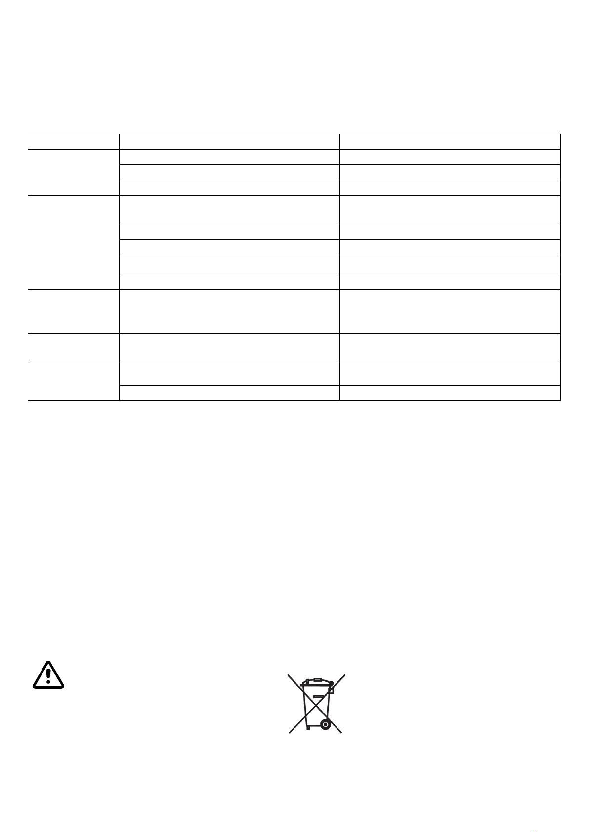
PROBLEM
CAUSE
REMEDY
The machine
doesn't start
Power supply plug disconnected
Connect the plug
Mains switch turned off
Turn on the main switch
Bowl peg sensor missing
Replace with a new one
Pressing the start
key, the
accessory does
not rotate
See previous causes
Connect the plug or turn on the mains
switch
Protection opened
Close the accident-prevention device
Emergency button pressed
Reset the emergency button
Bowl not positioned on the support
Position the bowl on the support
Bowl not in working position (high)
Bring the bowl into working position
The accessory
rotates counterclockwise
The phases of the machine do not
correspond with the power supply line
Ask a professional electrician to switch the
phases on the plug
Loss of RPM on
the accessory
Drive belts loosened or worn
Tighten the belts or replace them
Irregular rotation
of the accessory
Drive belt loosened or worn
Tighten or replace the belt
Eccentric pinion damaged
Replace the pinion
The laws in force at the time of disposal must be observed.
The symbol on the device, as illustrated here, indicates that it must not be disposed of as urban
waste, but must be transported separately to a WEEE collection centre specifically organised for the
adequate treatment of electrical and/or electronic apparatus. See Directive 2002/96/EC of the
European Parliament and Council dated 27 January 2003 on wastes from electrical and electronic
equipment.
Incorrect disposal or inappropriate use of the equipment or parts of it may cause potentially
negative and harmful effects on the environment and human health.
TROUBLE-SHOOTING
The following table indicates:
The description of the problem or the most likely symptoms of malfunctioning.
The cause/s of potential damage.
Remedies.
DECOMMISSIONING
Stop the work cycle of the machine.
Interrupt the electrical power supply using the mains switch n.1 to position 0.
Remove the power supply plug.
Move the machine to a storage facility.
Cover the machine with a nylon sheet.
Apply a sign with the words “OUT OF SERVICE”.
DISMANTLING AND DISPOSAL
No element of the machine must be disposed of in the environment.
Every part, component, or group of components must be separated according to the type of material.
22
Page 23

FRANÇAIS
Données du fabricant
Marquage CE
Symbole DEEE
Numéro de série
Année de fabrication
Modèle de la machine
Poids (Kg)
Tension (Volt)
Fréquence d’alimentation (Hz)
Nombre de phases
Courant absorbé (AMP.)
Puissance absorbée (KW)
ATTENTION : la cuve peut s’avérer lourde lors du déplacement manuel. L’opération doit être
effectuée par 2 opérateurs si le poids de la préparation est supérieur à 20 kg.
ATTENTION : manipuler les produits en poudre (farine, cacao, etc.) avec le plus grand soin, les vider
de leur boîte dans le fond de la cuve en évitant toute dispersion. Au besoin, utiliser un équipement
approprié pour la protection des voies respiratoires lors du chargement manuel des ingrédients en
poudre.
Les pièces mobiles de la machine sont protégées par des barrières physiques.
Il est strictement interdit de supprimer ou de modifier ces barrières.
Il est absolument interdit d’effectuer, sur la machine, toute intervention non prévue dans ce mode
d’emploi.
MARQUAGE DE LA MACHINE
Chaque machine est munie d’une plaque sur laquelle figurent les caractéristiques essentielles de la machine.
Notamment, la plaque fournit les informations suivantes (voir FIG. 3) :
INFORMATIONS GÉNÉRALES
Le mode d’emploi doit d’être considéré comme une partie intégrante de la machine, il doit être conservé pour
toute référence ultérieure pendant toute la durée de vie de la machine.
Avant toute intervention sur la machine, lire attentivement ce mode d’emploi et en particulier le chapitre
concernant la sécurité.
Le mode d’emploi doit être conservé de manière à être toujours accessible pour toute consultation et pour ne
pas être endommagé (endroit à l’abri des agents extérieurs, de l’humidité, de la poussière, des rayons du
soleil, etc...).
Le fabriquant se réserve le droit d’actualiser la production et les modes d’emploi correspondants sans pour
autant devoir actualiser la production et les modes d’emploi précédents.
Le fabricant est réputé dégagé de toute responsabilité dans les cas suivants :
- Mauvaise utilisation, utilisation incorrecte ou déraisonnable de la machine.
- Utilisation non-conforme aux réglementations nationales en vigueur.
- Mauvaise installation de la machine.
- Défauts d’alimentation.
- Entretien insuffisant par rapport à celui prévu.
- Modifications ou interventions non-autorisées.
- Utilisation de pièces de rechange et de produits non d’origine ou spécifiques pour le modèle.
- Non-respect des consignes.
À la réception de la machine et après l’avoir retirée de son emballage, s’assurer qu’elle est en bon état.
En cas de doute s’adresser à un personnel qualifié.
SITUATIONS DE DANGER
La machine présente les dangers suivants : pièces en mouvement et présence de tension. Les critères sur
lesquels se basent sa conception et sa fabrication ont permis de réduire considérablement le niveau de risque.
Pour le rendre pratiquement nul suivre impérativement les consignes de ce mode d’emploi.
Les risques résiduels qui n’ont pas pu être éliminés en raison des caractéristiques de travail de la machine et
qu’il faut constamment garder à l’esprit pour pouvoir les éviter sont :
23
Page 24

FRANÇAIS
UTILISATION PRÉVUE DE LA MACHINE
UTILISATION CORRECTE DE LA MACHINE
La machine est destinée à être utilisée par un personnel qualifié dans la production et la manipulation de
farines et de pâtes, et en particulier dans les ateliers de pâtisserie et de boulangerie.
Cette machine est un mélangeur planétaire : c’est-à-dire, elle sert à malaxer et mélanger tout type de
préparation pour la pâtisserie (crème, pâte, etc...). L’effet de malaxage est obtenu par le biais d’ustensiles
interchangeables inclus dans la fourniture qui agissent en tournant de façon planétaire, et qui grâce à leur
forme différente permettent différents modes d’utilisation.
PERFORMANCES DE LA MACHINE
Le moteur et la transmission par engrenages à bain d’huile permettent à la machine des performances
maximales avec la possibilité de mélanger même avec la cuve pleine.
En revanche, pour la préparation de pâtes à pain, pizza ou similaire, il est impératif de ne pas dépasser 1/3 (un
tiers) de la capacité de la cuve et avec un rapport eau/farine de 50 %.
Dans tous les cas, toujours respecter les données figurant dans le tableau DOSES CONSEILLÉES FIG. 5.
MAUVAISE UTILISATION DE LA MACHINE
La machine a été conçue uniquement pour l’utilisation prévue et décrite dans les paragraphes précédents.
Toute autre utilisation peut causer des dommages à la machine et/ou déterminer des situations de danger
pour lesquelles le Fabricant ne peut être tenu pour responsable.
Notamment, il est interdit de travailler toute autre matière (alimentaires ou non) ne répondant pas aux
exigences décrites ci-dessus.
DESCRIPTION TECHNIQUE
Toutes les données techniques sont fournies dans le tableau FIG. 6.
BUT
Mélanger, fouetter et amalgamer des ingrédients pour obtenir des préparations pour la pâtisserie et des
petites quantités de pâte à pain.
CYCLE DE TRAVAIL
Chargement des ingrédients : il est effectué manuellement par l’opérateur qui introduit les ingrédients dans
la cuve.
Déchargement de la préparation : il est effectué manuellement par l’opérateur qui retire la cuve et dépose la
préparation dans un endroit approprié.
Gestion : les opérations confiées au personnel lors du fonctionnement normal de la machine sont les
suivantes : mise en service, réglage, chargement, déchargement et arrêt au sein d’un procédé qui peut être
soit automatique soit manuel.
FABRICATION
Structure portante : elle supporte toutes les pièces impliquées dans la réalisation de la préparation.
Motorisation : grâce à un accouplement courroie, poulies et engrenages à graisse, elle produit le mouvement
rotatoire du groupe de mélange.
Groupe de mélange : ensemble des pièces contenant le produit et de mélange impliquées directement dans
la réalisation de la préparation.
Support de la cuve : système de support et de positionnement de la cuve, pour les opérations de chargement
et de déchargement des ingrédients.
Circuit électrique : tableau principal de dérivation et de distribution d’énergie électrique.
Tableau de commande : tableau de contrôle, paramétrage et commande de la production.
24
Page 25
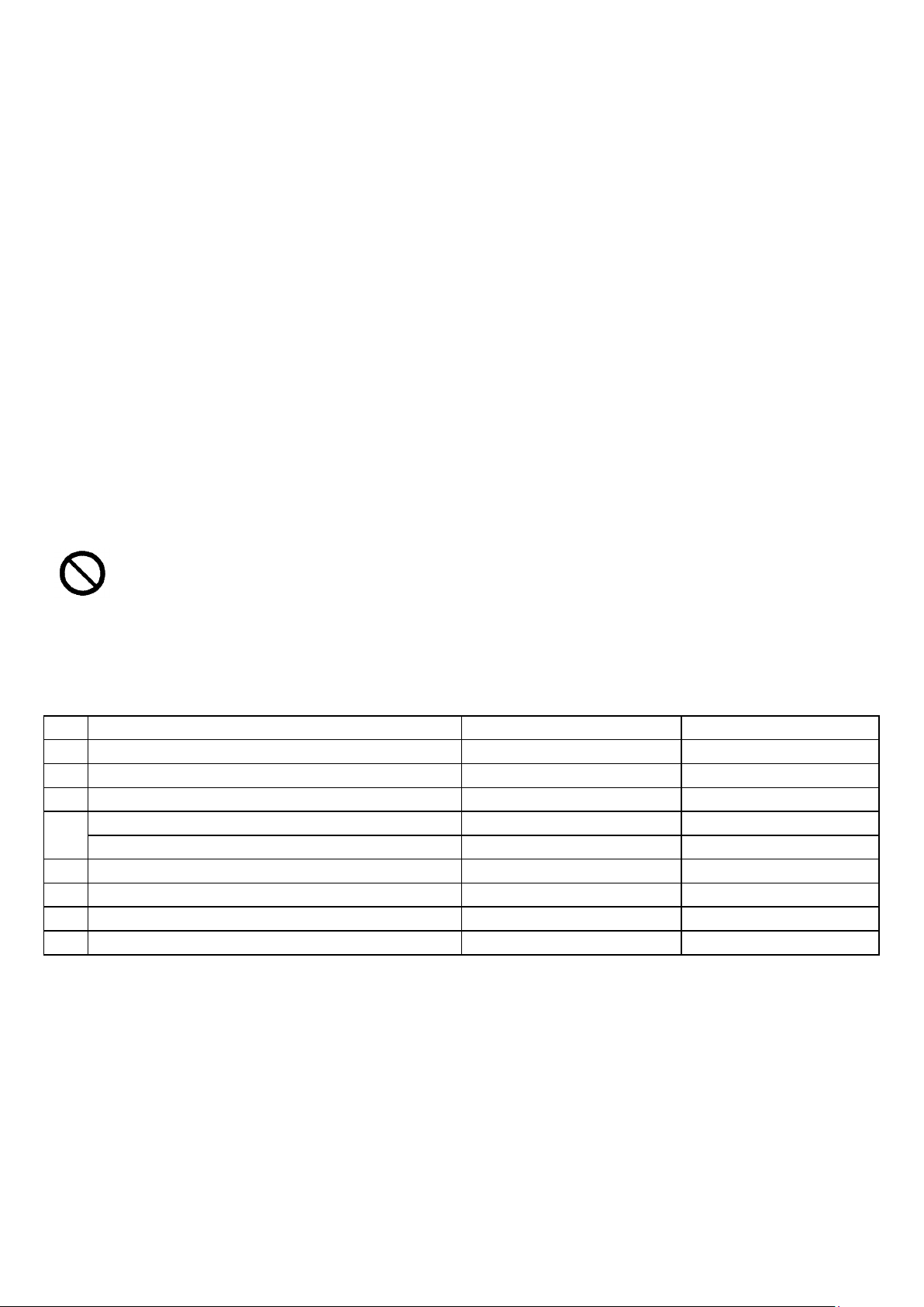
FRANÇAIS
BOUTON D’URGENCE
Bouton coup-de-poing rouge sur fond jaune qui interrompt
le fonctionnement de la machine en cas d’urgence.
PROTECTIONS FIXES ANTI-INTRUSION
Structure empêchant toute approche des parties
dangereuses.
MICRO-INTERRUPTEUR DE PRÉSENCE DE LA
CUVE
Il permet le démarrage de la machine uniquement si la cuve
est montée et bien positionnée.
MICRO-INTERRUPTEURS DE SÉCURITÉ
Ils arrêtent la machine en cas d’ouverture de la protection
pendant le fonctionnement.
PIEDS ANTI-VIBRATION
Ils réduisent la transmission des vibrations au sol.
IL EST ABSOLUMENT INTERDIT d’inhiber et/ou de modifier les dispositifs et les fonctions de
sécurité.
Pos.
Description
Actionneur
Couleur
1
Interrupteur général
Interrupteur
Rouge et jaune
2
Bouton d’urgence
Bouton
Rouge sur fond jaune
3
Écran minuteur
Écran LCD
4
Régulateur de vitesse
Volant-poignée
Activateur minuteur
Bouton
5 Démarrage/arrêt du moteur
2 boutons
6 Réglage minuteur
2 boutons
7 Blocage de la cuve
Poignée
8 Écran tr/min vitesse ustensile
Écran LCD
FONCTIONNEMENT
Introduction des ingrédients : l’opérateur introduit manuellement les ingrédients dans la cuve.
Cycle de travail : les ingrédients sont mélangés, pendant un temps défini préalablement, au moyen d’un
accessoire interchangeable, choisi en fonction de la préparation que l’on souhaite obtenir.
Déchargement de la préparation : l’opérateur retire manuellement la cuve du support de la machine et
décharge le contenu dans un endroit approprié.
ACCESSOIRES
Les accessoires disponibles pour la machine sont visibles dans le tableau FIG. 4.
DISPOSITIFS DE SÉCURITÉ
DESCRIPTION DES COMMANDES
MODÈLE AVEC VARIATEUR NUMÉRIQUE
Pour la description se référer à la FIG. 2.
25
Page 26

FRANÇAIS
CONDITIONS ENVIRONNEMENTALES
TEMPÉRATURE mini -5°C maxi 40°C
HUMIDITÉ RELATIVE maxi 50% à 40°C
ALTITUDE maxi 1000 m
EXIGENCES DU LIEU DE TRAVAIL
MILIEU :
Non explosif.
Non corrosif.
Pas soumis à de brusques changements de température.
À l’abri des intempéries et de tout contact direct avec l’eau.
ÉCLAIRAGE :
Diffus, ne créant pas de zones d’ombre à l’extérieur de la machine et de phénomènes d’éblouissement
ou stroboscopiques.
PLAN D’APPUI :
Plan horizontal et lisse.
Il doit pouvoir supporter un poids, selon le modèle (voir le tableau FIG. 6) en plus des charges déjà
présentes.
BRANCHEMENT ÉLECTRIQUE :
Tension d’alimentation 230/400 V, 50 Hz, avec une variation maximale de ± 10% pour la tension et de ± 1%
pour la fréquence.
La ligne d’alimentation doit être dimensionnée pour un courant nominal dépendant du modèle (voir le
tableau FIG. 6), protégée contre les surcharges, les courts-circuits et les contacts indirects (différentiel +
conducteur de protection) et avoir une chute de tension égale à ± 1 % de la tension de secteur.
N.B. consulter la documentation technique électrique jointe.
TRANSPORT ET MISE EN PLACE
La machine est envoyée dans un seul colis, entièrement assemblée. Pour l’envoi depuis l’usine du fabricant, la
machine est placée et immobilisée sur une palette et, si nécessaire ou contractuellement prévu, dans un
emballage en carton de grosse épaisseur (grand carton) ou en bois (cage). Manutentionner/transporter la
machine en prenant toutes les précautions nécessaires pour prévenir ou limiter tout risque pour les
personnes ou les biens.
Le chargement/déchargement sur/du moyen de transport s’effectue normalement avec un chariot
élévateur/un transpalette d’une capacité adéquate (voir le tableau FIG. 6) en insérant les fourches du
dispositif dans les espaces appropriés à la base de la palette.
INSTALLATION
1) Ouvrir la caisse en bois utilisée pour le transport (si présente).
2) Retirer le plastique qui protège la machine.
3) Libérer la machine de son ancrage à la palette.
4) Soulever la machine avec un câble de levage en la prenant sous la tête et la déposer à l’endroit où elle
sera installée.
5) Veiller à laisser un espace minimal de 30 cm par rapport à toute autre machine ou mur.
6) S’assurer que la machine adhère parfaitement au sol en réglant éventuellement les 4 écrous sous la
base pour la fixation définitive des pieds stabilisateurs au sol.
7) Bancher la fiche d’alimentation électrique à la prise commandée installée par le client.
8) S’assurer que l’ustensile tourne dans le bon sens (voir la flèche), et si ce n’est pas le cas, arrêter
immédiatement la machine et inverser une phase de la fiche d’alimentation (uniquement personnel
expert).
26
Page 27

FRANÇAIS
9) Séparer les matériaux par type (carton, plastique, bois, etc.) et les déposer dans des lieux de collecte
appropriés, accessibles uniquement aux personnes autorisées, en attendant qu’ils soient éliminés par
des entreprises spécialisées. Les poutrelles en bois et la palette doivent aussi être déposées dans un lieu
de collecte spécialement prévu à cet effet.
UTILISATION DE LA MACHINE
Le fonctionnement de la machine est le suivant :
PRÉPARATION
1) Insérer la fiche dans la prise de courant.
2) Mettre la machine sous tension en agissant sur l’interrupteur général 1.
3) Ouvrir la protection permettant l’accès à la zone du mélangeur.
4) Soulever le manchon de blocage des accessoires.
5) Remplacer l’outil présent par celui souhaité.
6) Baisser le manchon en veillant à introduire la vis sans tête arrière dans la fente du manchon.
7) Fermer la grille de protection.
8) Lire attentivement les indications figurant sur la plaque FIG.3.
9) Procéder aux opérations de préparation ou agir sur l’interrupteur général 1 pour arrêter la machine.
10) Retirer la fiche d’alimentation électrique de la prise (si nécessaire).
PHASES DE TRAVAIL FIG. 2
L’opérateur suit visuellement le cycle de travail et intervient en personne à l’arrêt des opérations.
1) Insérer la fiche dans la prise de courant.
2) Mettre la machine sous tension en agissant sur l’interrupteur général 1.
3) Ouvrir la protection permettant l’accès à la zone du mélangeur.
4) Introduire les ingrédients dans la cuve.
5) Fermer la grille de protection.
6) Activer le minuteur en appuyant sur la poignée N°4.
7) Régler le minuteur sur les minutes souhaitées (de 0 à 99), ou appuyer sur la poignée N°4 pour exclure
l’utilisation du minuteur.
8) Lancer le cycle en appuyant sur le bouton N°3 de démarrage du moteur
9) Agir sur la poignée N°4, selon l’expérience acquise, pour régler la vitesse :
- Réglage minimum 40 tours/minute (vers la gauche)
- Réglage maximum 200 tours/minute (vers la droite)
10) Lancer le cycle.
11) Une fois le cycle terminé, appuyer sur le bouton N°2 pour l’arrêter.
(ou attendre que le temps réglé soit épuisé - en cas d’arrêt du minuteur pour une pause, le temps
écoulé reste en mémoire et le minuteur repartira à partir du temps restant)
12) Ouvrir la protection.
13) Ôter l’accessoire de mélange.
14) Soulever la cuve en la dégageant des 2 blocages latéraux (7) pour l’extraire.
15) Prendre la cuve et vider son contenu dans un récipient approprié.
16) Nettoyer correctement la cuve et toutes les pièces en contact avec les ingrédients.
17) Placer la cuve et la bloquer dans les deux crans (7).
18) Pour reprendre le travail revenir à l’étape 5 ou continuer.
19) Fermer la protection.
20) Agir sur l’interrupteur général 1 pour mettre la machine hors tension.
21) Enlever la fiche d’alimentation du circuit électrique.
27
Page 28

FRANÇAIS
Danger : pour des raisons de sécurité toutes les opérations de nettoyage doivent être effectuées
lorsque la machine est à l’arrêt et déconnectée de l’alimentation électrique.
NETTOYAGE DE LA MACHINE
La cuve, la protection rotative de sécurité et l’ustensile sont entièrement amovibles pour permettre leur
nettoyage.
ATTENTION : les ustensiles en aluminium doivent être nettoyés exclusivement avec de l’eau pour éviter leur
oxydation.
IMPORTANCE DU NETTOYAGE
Le nettoyage correct et ponctuel de la machine non seulement contribue à la conserver dans de bonnes
conditions d’efficacité, mais est aussi d’une importance capitale. En effet, un manque d’hygiène peut être une
cause de risques pour la santé humaine et d’une altération inadmissible du produit alimentaire.
Il est donc recommandé à l’utilisateur de respecter scrupuleusement les instructions de nettoyage ci-après,
en utilisant uniquement les produits indiqués afin d’éviter tout dommage aux différentes pièces de la
machine. La machine doit être nettoyée à la fin de chaque cycle de travail.
PRODUITS POUR LE NETTOYAGE
Pour le nettoyage de la machine, mis à part les pièces internes, utiliser un détergent biodégradable sans
phosphore et sans chlorures. En particulier, pour le nettoyage des cuves, des bacs et des récipients en acier
inoxydable, il est recommandé d’utiliser uniquement un détergent biodégradable pour vaisselle et lavevaisselle au pH neutre.
INSTRUCTIONS POUR LE NETTOYAGE
AVERTISSEMENTS GÉNÉRAUX CONCERNANT LE NETTOYAGE ET LE LAVAGE
NE PAS UTILISER de détergents contenant des produits chimiques agressifs/irritants et non biodégradables.
NE PAS UTILISER de jets d’eau ou de nettoyeurs à haute pression.
NE PAS UTILISER de détergents contenant du triéthylène ou du chlorothène.
NE PAS UTILISER de jets d’air comprimé dans la mesure où, produisant de la poussière, ils sont
nuisibles à la santé ; il est en revanche conseillé d’utiliser un aspirateur.
NE PAS UTILISER, pour le nettoyage, de l’eau à une température de plus de 60 °C, de solutions à base
de soude caustique, d’acide chlorhydrique ou d’acide sulfurique, car nuisibles pour les surfaces.
28
Page 29
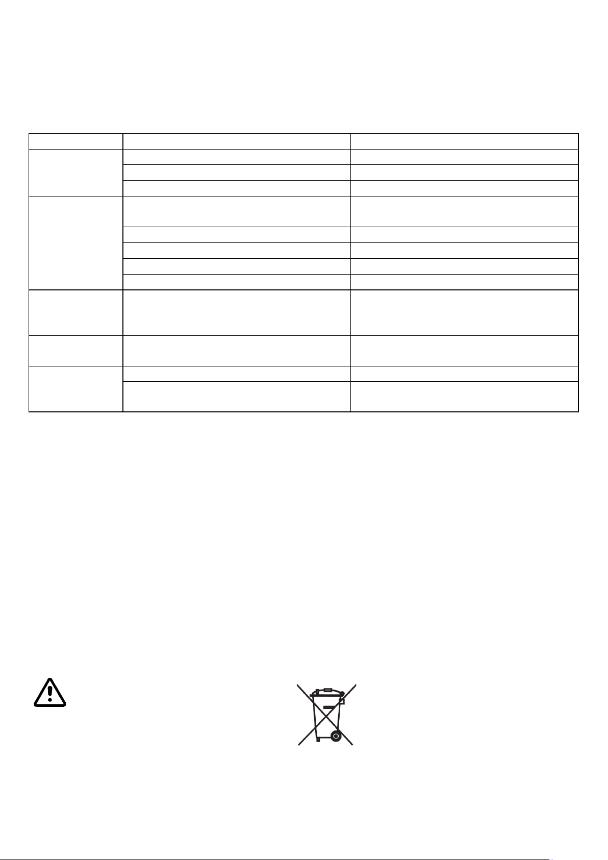
FRANÇAIS
ANOMALIE
CAUSE
REMÈDE
La machine ne
démarre pas
Fiche d’alimentation débranchée
Insérer la fiche
Interrupteur général désactivé
Activer l’interrupteur général
Broche du capteur de cuve absente
Remplacer par une nouvelle
En appuyant sur
le bouton de
marche
l’accessoire ne
tourne pas
Voir les causes précédentes
Insérer la fiche et activer l’interrupteur
général
Protection ouverte
Fermer la protection
Bouton d’urgence actionné
Réarmer le bouton d’urgence
Cuve hors de son support
Placer la cuve sur son support
Cuve pas dans la position de travail (haute)
Placer la cuve en position de travail
L’accessoire
tourne vers la
gauche
Les phases de la machine ne correspondent
pas à la ligne d’alimentation
S’adresser à un électricien professionnel
pour inverser les fils des phases sur la fiche
électrique de connexion
Perte de vitesse
de l’accessoire
Courroies de transmission détendues ou
usées
Tendre les courroies ou les remplacer
Rotation
irrégulière de
l’accessoire
Courroie de transmission détendue ou usée
Tendre la courroie ou la remplacer
Pignon de la came endommagé
Remplacer le pignon
Suivre les dispositions des lois en vigueur à la date de la mise au rebut.
Le symbole apposé sur l’équipement, et illustré ici, indique que ce produit ne doit pas être éliminé
en tant qu’ordure ménagère. Il doit être mis au rebut séparément auprès d’un point de collecte
DEEE prévu spécialement pour le traitement conforme des appareils électriques et/ou
électroniques. Référence Directive 2002/96/CE du Parlement Européen et du Conseil du 27/01/03
relative aux déchets d’équipements électriques et électroniques.
Une élimination inappropriée ou une mauvaise utilisation de l’appareil ou de l’une de ses parties,
pourrait avoir des effets potentiellement négatifs et nuisibles pour l’environnement et pour la santé
des gens.
PANNES ET/OU ANOMALIES POSSIBLES
Le tableau suivant contient :
La description du problème, à savoir les symptômes de dysfonctionnement les plus probables.
La ou les cause(s) de dommage possible(s).
Les solutions proposées.
MISE HORS SERVICE
Arrêter le cycle de travail de la machine.
Couper l’alimentation électrique en tournant l’interrupteur général 1 sur la position 0.
Retirer la fiche d’alimentation du circuit électrique.
Déplacer la machine dans un lieu de stockage.
Couvrir la machine avec un plastique.
Apposer un écriteau indiquant « Hors service ».
MISE AU REBUT
Aucun élément de la machine ne doit être abandonné dans la nature.
Chaque partie, composant ou groupe de composants doit être regroupé selon le type de matériau.
29
Page 30

ESPAÑOL
Datos del fabricante
Marca CE
Símbolo RAEE
Número de serie
Año de construcción
Modelo de la máquina
Peso (kg)
Voltaje (V)
Frecuencia de alimentación (Hz)
Número de fases
Corriente absorbida (A)
Potencia absorbida (kW)
ATENCIÓN: La cubeta puede resultar pesada para su desplazamiento manual. Si el peso de la masa
supera los 20 kg, esta operación debe ser realizada por dos operadores.
ATENCIÓN: Manipule con extremo cuidado los productos en polvo (harina, cacao, etc.); extráigalos
de su envase en la parte inferior de la cuba, evitando su dispersión. Si es necesario, utilice
adecuados equipos de protección de las vías respiratorias durante la carga manual de los
ingredientes en polvo.
Los órganos en movimiento de la máquina están protegidos mediante barreras físicas.
Está terminantemente prohibido quitar o alterar dichas barreras.
Está terminantemente prohibido realizar cualquier operación en la máquina que no esté prevista en
el presente manual.
MARCADO DE LA MÁQUINA
Cada máquina está dotada de una placa que indica sus características esenciales.
Los datos presentes en la placa son los siguientes (véase la fig. 3):
INFORMACIÓN GENERAL
El manual se debe considerar parte integrante de la máquina y se debe conservar para futuras referencias
hasta el final de su vida útil.
Antes de realizar cualquier operación en la máquina, lea atentamente el presente manual de instrucciones y,
en particular, el capítulo sobre la seguridad.
El manual se debe conservar de tal forma que esté siempre protegido y disponible para su lectura (lugar
protegido de los agentes externos, humedad, polvo, rayos solares, etc.).
El fabricante se reserva el derecho a actualizar la producción y los manuales de instrucciones, sin obligación de
actualizar la producción y los manuales anteriores.
El fabricante se exime de cualquier responsabilidad derivada de:
- uso incorrecto, erróneo o irracional de la máquina;
- uso contrario a la normativa nacional vigente;
- instalación incorrecta de la máquina;
- defectos de alimentación;
- insuficiente mantenimiento;
- modificaciones o intervenciones no autorizadas;
- uso de repuestos no originales o no específicos para el modelo;
- incumplimiento de las instrucciones.
Al recibir el envío, una vez quitado el embalaje, verifique la integridad de la máquina.
En caso de dudas, diríjase a personal cualificado.
SITUACIONES DE PELIGRO
La máquina presenta algunos peligros como, por ejemplo, componentes en movimiento y presencia de
tensión. Los criterios con que la máquina está proyectada y construida han permitido reducir
significativamente el nivel de riesgo; para alcanzar un nivel prácticamente nulo, se deben seguir estrictamente
las indicaciones del presente manual.
Los riesgos residuales que no ha sido posible eliminar a causa de las características de funcionamiento de la
máquina, y que se deben tener siempre presentes para poder evitarlos, son los siguientes:
30
Page 31

ESPAÑOL
USO PREVISTO DE LA MÁQUINA
USO CORRECTO DE LA MÁQUINA
La máquina está diseñada para ser utilizada por personal cualificado en la producción y manipulación de
harinas y masas; en particular, en talleres de repostería y panificación.
Se trata de una máquina amasadora planetaria para amasar y mezclar cualquier tipo de masa de repostería
(cremas, nata, masa, etc.). El amasado se obtiene mediante el uso de herramientas intercambiables
suministradas de serie, que giran en forma planetaria y tienen diferentes formas, con diferentes modos de
uso.
POTENCIA DE LA MÁQUINA
El motor y la transmisión de engranajes en baño de aceite garantizan una elevada potencia de la máquina, con
la posibilidad de funcionar incluso con la cuba llena.
Por el contrario, para elaborar masas para pan, pizza o similares, no se debe superar 1/3 (un tercio) de la
capacidad de la cuba, con una relación de agua/harina del 50 %.
Respete siempre los datos indicados en la tabla DOSIS RECOMENDADAS (fig. 5).
USO INCORRECTO DE LA MÁQUINA
La máquina ha sido proyectada solo para el uso descrito en los párrafos anteriores.
Cualquier otro uso puede provocar daños a la máquina y/o generar situaciones de peligro de las que el
fabricante no puede ser considerado responsable.
En particular, no está permitido elaborar ningún tipo de material (alimentario o no) que no responda a los
requisitos descritos.
DESCRIPCIÓN TÉCNICA
Todos los datos técnicos están indicados en la tabla de la fig. 6.
OBJETIVO
Mezcla, bate y amalgama ingredientes para obtener masas de repostería y pequeñas masas de panificación.
CICLO DE TRABAJO
Carga de los ingredientes: Es realizada manualmente por el operador, que introduce los ingredientes en la
cubeta.
Descarga de la masa: Es realizada manualmente por el operador, que toma la cubeta y deposita la masa en el
lugar previsto.
Conducción. Las operaciones encomendadas al personal durante el uso normal de la máquina son las
siguientes: puesta en funcionamiento, regulación, carga, descarga y parada, en un proceso que puede ser
automático o manual.
CONSTRUCCIÓN
Estructura portante: Sostiene todas las partes que intervienen en la elaboración de la masa.
Motorización: Mediante el acoplamiento de la correa, las poleas y los engranajes engrasados, proporciona el
movimiento giratorio al grupo de mezcla.
Grupo de mezcla: Conjunto de componentes de contención y mezcla que intervienen directamente en la
elaboración de la masa.
Soporte de la cubeta: Sistema de soporte y fijación de la cubeta, para las operaciones de carga y descarga de
los ingredientes.
Instalación eléctrica: Cuadro principal de derivación y distribución de energía eléctrica.
Cuadro de mandos: Cuadro de control, regulación y mando de la producción.
31
Page 32

ESPAÑOL
BOTÓN DE EMERGENCIA
Seta roja con base amarilla que interrumpe el
funcionamiento de la máquina en caso de emergencia.
PROTECCIÓN FIJA ANTIINTRUSIÓN
Estructura que impide acercarse a las partes peligrosas.
MICROINTERRUPTOR DE PRESENCIA DE
CUBETA
Permite la puesta en marcha de la máquina solo si la cubeta
está colocada y fijada correctamente
MICROINTERRUPTORES DE SEGURIDAD
Detienen la máquina en caso de apertura de la protección
durante el funcionamiento.
PATAS ANTIVIBRATORIAS
Reducen la transmisión de las vibraciones al piso.
ESTÁ TERMINANTEMENTE PROHIBIDO inhibir y/o alterar los dispositivos y funciones de seguridad.
Pos.
Descripción
Actuador
Color
1
Interruptor general
Interruptor
Rojo y amarillo
2
Botón de emergencia
Botón
Rojo con fondo amarillo
3
Display temporizador
Pantalla LCD
4 Regulador de velocidad
Volante-llave
Activador temporizador
Botón
5 Arranque/parada motor
2 botones
6 Configuración temporizador
2 botones
7 Bloqueo cubeta
8
Display rpm velocidad herramienta
Pantalla LCD
FUNCIONAMIENTO
Introducción de los ingredientes: Es realizada manualmente por el operador, que introduce en la cubeta los
ingredientes.
Ciclo de elaboración: Los ingredientes se mezclan durante un tiempo preestablecido, mediante un accesorio
intercambiable según la masa que se desea obtener.
Descarga de la masa: Es realizada manualmente por el operador, que toma la cubeta del soporte de la
máquina y descarga el contenido en el lugar previsto.
ACCESORIOS
Los accesorios disponibles para esta máquina se enumeran en la tabla de la fig. 4.
DISPOSITIVOS DE SEGURIDAD
DESCRIPCIÓN DE LOS MANDOS
MODELO CON VARIADOR DIGITAL
Para su descripción, remítase a la fig. 2.
32
Page 33

ESPAÑOL
CONDICIONES AMBIENTALES
TEMPERATURA mín. -5 °C - máx. 40 °C
HUMEDAD RELATIVA máx. 50 % a 40 °C
ALTITUD máx. 1000 m
REQUISITOS DEL LUGAR DE TRABAJO
AMBIENTE:
No explosivo.
No corrosivo.
No debe presentar oscilaciones bruscas de la temperatura.
Protegido de la intemperie y del contacto directo con el agua.
ILUMINACIÓN:
La iluminación debe ser difusa, no debe crear conos de sombra fuera de la máquina y no debe crear
fenómenos estroboscópicos o de deslumbramiento.
SUPERFICIE DE APOYO:
Superficie horizontal y lisa.
Debe sostener el peso correspondiente al modelo (véase la tabla de la fig. 6), además de las cargas ya
presentes.
CONEXIÓN ELÉCTRICA:
Tensión de alimentación 230/400 V, 50 Hz, con una variación máxima del ± 10 % para la tensión y del ± 1 %
para la frecuencia.
La línea de alimentación debe estar dimensionada para la corriente nominal correspondiente al modelo
(véase la tabla de la fig. 6), protegida contra sobrecargas, cortocircuitos y contactos indirectos (diferencial +
conductor de protección), con una caída de tensión correspondiente al ± 1 % de la tensión de red.
Nota: Consulte la documentación técnica eléctrica adjunta.
TRANSPORTE E INSTALACIÓN
La máquina se envía en un solo bulto, completamente montada. Para el envío desde la sede del fabricante, la
máquina se coloca en un palé y, si es necesario o está previsto en el contrato, en un embalaje de cartón de
elevado espesor (caja) o madera (jaula). Durante el desplazamiento/transporte de la máquina, tome todas las
precauciones necesarias para evitar o limitar los riesgos para las personas y objetos.
Generalmente, la carga/descarga del medio de transporte se realiza con una carretilla elevadora/transpaleta
de capacidad adecuada (véase la tabla de la fig. 6), cuyas horquillas se deben introducir en los espacios
correspondientes en la base del palé.
INSTALACIÓN
1) Abra la caja de madera utilizada para el transporte (si corresponde).
2) Quite el nailon protector de la máquina.
3) Libere la máquina de sus anclajes al palé.
4) Levante la máquina con un cable de elevación, tomándola debajo de la cabeza, y colóquela en el lugar
previsto para su instalación.
5) Verifique que haya una distancia mínima de 30 cm entre la máquina y cualquier otra máquina o pared.
6) Verifique que la máquina se apoye perfectamente en el piso, regulando eventualmente las 4 tuercas
presentes en la base para la fijación definitiva de las patas estabilizadoras.
7) Inserte el enchufe de alimentación de la instalación eléctrica en la toma con interruptor instalada por el
comprador.
8) Verifique el correcto sentido de rotación de la herramienta (véase la flecha correspondiente); si gira en
sentido contrario, detenga inmediatamente la máquina y haga invertir una fase del enchufe de
alimentación (esta operación debe ser realizada exclusivamente por personal especializado).
33
Page 34

ESPAÑOL
9) Separe los materiales por tipo (cartón, plástico, madera, etc.) y colóquelos en los lugares de recogida
correspondientes, accesibles exclusivamente al personal autorizado, a la espera de su eliminación por
empresas especializadas. Los travesaños de madera y el palé también se deben colocar en un lugar
especialmente destinado a tal fin.
USO DE LA MÁQUINA
El funcionamiento de la máquina se desarrolla en la forma siguiente:
PREPARACIÓN
1) Inserte el enchufe en la toma de corriente.
2) Conecte la tensión de la máquina accionando el interruptor general 1.
3) Abra la protección de acceso a la zona del mezclador.
4) Levante el manguito de bloqueo de los accesorios.
5) Extraiga el accesorio presente y sustitúyalo con el deseado.
6) Baje el manguito, introduciendo el tornillo prisionero posterior en la ranura del mismo.
7) Cierre la protección de red.
8) Lea atentamente las indicaciones de la placa fig.4.
9) Proceda a la elaboración o accione el interruptor general 1 para detener la máquina.
10) Extraiga el enchufe de alimentación eléctrica de la toma (si es necesario).
FASES DE TRABAJO FIG. 2
El operador controla visualmente el ciclo de trabajo e interviene personalmente al detenerse la elaboración.
1) Inserte el enchufe en la toma de corriente.
2) Conecte la alimentación de la máquina accionando el interruptor general 1.
3) Abra la protección de acceso a la zona del mezclador.
4) Introduzca los ingredientes en la cubeta.
5) Cierre la protección de red.
6) Active el temporizador, presionando el pomo n.º 4.
7) Configure en el temporizador los minutos deseados (de 0 a 99) o presione el pomo n.º 4 para excluir el
temporizador.
8) Inicie la elaboración, pulsando el botón n.º 3 de arranque del motor.
9) Sobre la base de la experiencia adquirida, gire el pomo n.º 4 para regular la velocidad:
- de un mínimo de 40 revoluciones por minuto (hacia la izquierda)
- a un máximo de 200 revoluciones por minuto (hacia la derecha.)
10) Inicie la elaboración.
11) Al final de la elaboración, pulse el botón n.º 2 para interrumpir el ciclo
(o espere hasta que termine el tiempo configurado; si el temporizador se interrumpe por una pausa,
conserva en la memoria el tiempo transcurrido y se reactivará solo para completar el tiempo faltante).
12) Abra la protección.
13) Quite el accesorio de mezcla.
14) Levante la cuba, extrayéndola de las 2 trabas laterales (7).
15) Tome la cubeta y vacíe el contenido en un recipiente destinado a tal fin.
16) Limpie cuidadosamente la cubeta y todas las partes en contacto con el material elaborado.
17) Coloque la cubeta y bloquéela en las dos patillas (7).
18) Si desea reanudar la elaboración, vuelva a la fase n.º 5 o continúe.
19) Cierre la protección.
20) Accione el interruptor general 1 para interrumpir la alimentación de la máquina.
21) Extraiga el enchufe de alimentación de la instalación eléctrica.
34
Page 35

ESPAÑOL
Peligro: Por motivos de seguridad, todas las operaciones de limpieza se deben realizar con la
máquina parada y desconectada de la red eléctrica de alimentación.
LIMPIEZA DE LA MÁQUINA
La cuba, la protección giratoria y la herramienta son totalmente extraíbles para permitir su limpieza.
ATENCIÓN: Las herramientas de aluminio se deben limpiar exclusivamente con agua para evitar su oxidación.
IMPORTANCIA DE LA LIMPIEZA
Además de contribuir a mantenerla en condiciones de eficiencia, la correcta y puntual limpieza de la máquina
es de fundamental importancia. En efecto, la falta de higiene puede generar riesgos para la salud humana y
alteraciones inaceptables del producto alimentario.
Por este motivo se recomienda al usuario seguir escrupulosamente las instrucciones de limpieza que se
describen a continuación, utilizando exclusivamente los productos indicados con el objetivo de no causar
daños a las diferentes partes de la máquina. Esta se debe limpiar al final de cada turno de trabajo.
PRODUCTOS PARA LA LIMPIEZA
Para la limpieza de la máquina (excepto las partes internas) utilice detergente biodegradable, sin fósforo ni
cloruros. En particular, para la limpieza de las cubas, cubetas y recipientes de acero inoxidable, se recomienda
utilizar exclusivamente detergente biodegradable para vajilla o para lavavajillas con pH neutro.
INSTRUCCIONES DE LIMPIEZA
ADVERTENCIAS GENERALES SOBRE LA LIMPIEZA Y EL LAVADO
NO UTILICE detergentes que contengan productos químicos agresivos, irritantes o no biodegradables.
NO UTILICE chorros de agua o hidrolimpiadoras.
NO UTILICE detergentes que contengan tricloroetileno o tricloroetano.
NO UTILICE chorros de aire comprimido, ya que esto levanta polvo y es perjudicial para la salud; se
recomienda utilizar un aspirador.
NO UTILICE agua a más de 60 °C, soluciones a base de soda cáustica, ácido clorhídrico o ácido sulfúrico,
ya que son perjudiciales para las superficies.
35
Page 36
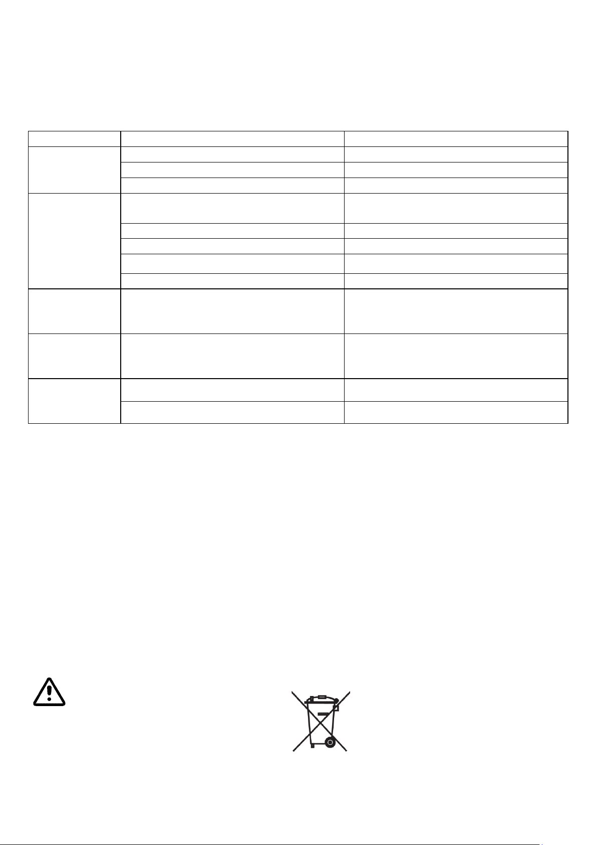
ESPAÑOL
ANOMALÍA
CAUSA
SOLUCIÓN
La máquina no se
enciende.
Enchufe de alimentación desconectado
Inserte el enchufe
Interruptor general desconectado
Accione el interruptor general
Patilla de sensor de cuba faltante
Sustitúyala con una nueva
Pulsando el
botón de
marcha, la
herramienta no
gira.
Véanse las causas anteriores
Inserte el enchufe y accione el interruptor
general
Protección abierta
Cierre el resguardo de seguridad
Botón de emergencia pulsado
Desbloquee el botón de emergencia
Cubeta no colocada en el soporte
Coloque la cubeta en el soporte
Cubeta no en posición de trabajo (alta)
Ponga la cubeta en posición de trabajo
La herramienta
gira en sentido
levógiro.
Las fases de la máquina no corresponden a
la línea de alimentación
Consulte a un electricista profesional para
intercambiar los conductores de las fases en
el enchufe de conexión
Pérdida de
revoluciones de
la herramienta.
Correas de transmisión flojas o desgastadas
Tense o sustituya las correas
Rotación
irregular de la
herramienta.
Correa de transmisión floja o desgastada
Tense o sustituya la correa
Piñón del excéntrico dañado
Sustituya el piñón
Es obligatorio seguir las prescripciones de las leyes vigentes en el momento la eliminación.
El símbolo aplicado en el aparato (véase a continuación) indica que este no se debe eliminar como
residuo urbano normal, sino que debe ser entregado por separado a un centro de recogida RAEE,
específicamente preparado para el tratamiento conforme a la normativa de los aparatos eléctricos
y/o electrónicos. Referencia Directiva 2002/96/CE del Parlamento Europeo y del Consejo del
27/1/2003 sobre los residuos de aparatos eléctricos y electrónicos.
El incorrecto uso o eliminación del aparato o de sus partes puede producir efectos potencialmente
negativos y perjudiciales para el ambiente y la salud de las personas.
POSIBLES AVERÍAS Y/O ANOMALÍAS
La siguiente tabla indica:
la descripción del problema o de los síntomas de disfunción más probables;
la o las causas posibles de la avería;
las soluciones propuestas.
PUESTA FUERA DE SERVICIO
Interrumpa el ciclo de trabajo de la máquina.
Interrumpa la distribución de energía eléctrica, poniendo el interruptor general n.° 1 en la posición 0.
Extraiga el enchufe de alimentación de la instalación eléctrica.
Coloque la máquina en el lugar previsto para su almacenamiento.
Cubra la máquina con un nailon.
Coloque un cartel con la indicación “Fuera de servicio”.
DESMANTELAMIENTO
No se debe dispersar ningún elemento de la máquina en el ambiente.
Cada parte, componente o grupo de componentes debe ser agrupado según el tipo de material.
36
Page 37
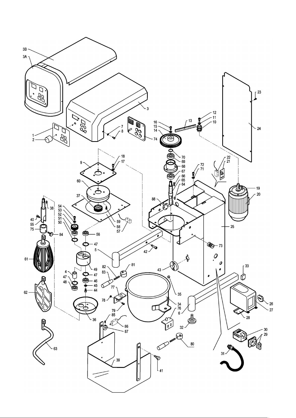
RICAMBI / SPARE PARTS
LT 5 – LT 8 – LT 10
Page 38

POS.
DESCRIZIONE
DENOMINATION
1
Pannello adesivo
Front label
2
Manopola variatore
Variator speed handwheel
3
Coperchio superiore
Top cover
4
Distanziale
Spacer ring
5
Supporto –gamba SX
Left support-basement
6
Supporto – gamba DX
Right support-basement
7
Rondella
Ring
8
Vite
Screw
9
Piastra testata porta-corona
Head-Crown support
10
Puleggia Motrice
Motor pulley
11
Rondella
Ring
12
Vite
Screw
13
Cinghia Dentata
Tooothed belt
14
Puleggia
Pulley
15
Rondella
Ring
16
Vite
Screw
17
Rondella
Ring
18
Vite
Screw
19
Linguetta
Pin
20
Motore M71c 4poli
Motor
21
Staffa Porta Micro Magnetico
Microsw. Support
22
Sensore E510
Microsw-Sensor E510
23
Vite
Screw
24
Carter Chiusura Posteriore
Back cover
25
Assieme Carpenteria LT. 5/8/10
Carpentry – structure
26
Blocchetto di arresto
Stop block-switch
27
Inverter
Inverter
28
Omega Porta Inverter
Support for Inverter
29
Manopola Rossa 60x60
Red handwheel 60x60
30
Blocco 3p 25°
Main switch
31
Pressacavo
Cable support
32
Piedino A Ventosa
Rubber foot
33
Trimmer 5k 63p
Trimmer 5k 63p
34
Vasca
Bowl
35
Plastogommosa
Magnete
36
Coppa chiusura eccentrico
Cam plastic cover
37
Pignone Per Albero Centrale
Main shaft pinion
38
Linguetta
Pin
39
Protezione Mobile LT. 5/8/10 Banco
Inox guard
40
Vite
Screw
41
Volantino zigrinato
Handwheel
42
Controdado Pg9 Plastica
Bolt
43
Boccola Piolo Vasca P
Bowl pin support
44
Vite
Screw
45
Rondella
Ring
46
Cuscinetto 6002 2RS1
Bearing
47
Seeger I
Ring Seeger I
Page 39

48
Cuscinetto 6002 2RS1
Bearing
49
Eccentrico LT. 5/8/10
Cam
50
Seeger I
Ring Seeger I
51
Cuscinetto 6002 2RS1
Bearing
52
Pignone Per Eccentrico
Cam pinion
53
Rondella
Ring
54
Vite
Screw
55
Albero Porta Utensile LT. 5/8/10
Mandrel shaft
56
Cuscinetto 6002 2RS1
Bearing
57
Sensore E510 (solo per LT. 5)
Microsw. Sensor E510 (only LT.5)
58
Piastra chiusura inferiore testata
Inferior Head support
59
Vite
Screw
60
Corona LT. 5/8/10
Crown
61
Frusta
Whisk
62
Spatola
Spatula-beater
63
Utensile A Spirale
Spiral tool
64
Linguetta
Pin
65
Albero Porta Eccentrico
Cam support shaft
66
Linguetta
Pin
67
Cuscinetto 6203 2RS1
Bearing
68
Supporto Albero Porta Eccentrico
Shaft support
69
Cuscinetto 6203 2RS1
Bearing
70
Seeger I
Ring Seeger I
71
Rondella
Ring
72
Vite
Screw
73
Fermo Protezione Mobile
Mobil guard support
74
Scheda elettronica Plc
Electronic card
75
Manicotto Fissaggio Utensile LT. 5/8/10
Shaft collar
76
Supporto porta vasca DX
Right bowl support
77
Supporto porta vasca SX
Left bowl support
78
Dado
Nut
79
Vite
Screw
80
Manopola DX di bloccaggio vasca
Right fixing bowl lever
81
Manopola SX di bloccaggio vasca
Left fixing bowl lever
82
Impugnatura per bloccaggio vasca - 2
Fixing bowl handlever – 2
83
Vite per impugnatura - 2
Screw – 2
84
Nottolino fissaggio manicotto utensile
Pawl mounting tool sleeve
85
Grano di fissaggio
Fixing screw
86
Microinterruttore per protezione (solo per LT. 8 e 10)
Guard microswitch (only LT. 8 and 10)
87
Camma di comando micro
Micro cam
88
Supporto micro
Micro support
Page 40
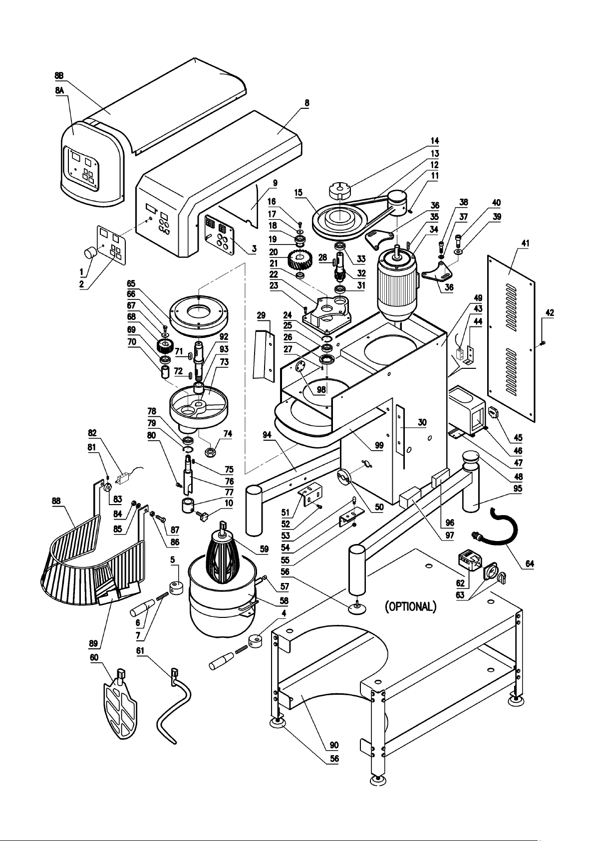
LT 20
Page 41

POS
DENOMINAZIONE
DENOMINATION
1
Potenziometro x regolazione RPM – velocità utensile
RPM vari-speed handwheel
2
Pannello adesivo dei comandi
Control panel label
3
Scheda di comando PLC
PLC electronic card
4
Manopola DX di bloccaggio vasca
Right fixing bowl lever
5
Manopola SX di bloccaggio vasca
Left fixing bowl lever
6
Impugnatura per bloccaggio vasca - 2
Fixing bowl handlever – 2
7
Vite per impugnatura - 2
Screw – 2
8
Coperchio anteriore testata
Front head cover
9
Riparo parapolvere
Cover
10
Nottolino fissaggio manicotto utensile
Pawl mounting tool sleeve
11
Grano fissaggio puleggia
Screw for pulley
12
Puleggia motrice
Motor pulley
13
Cinghia di trasmissione
Transmission belt
14
Calettatore x puleggia
Pulley clamping
15
Puleggia condotta
Driven pulley
16
Vite
Screw
17
Rondella
Ring
18
Cuscinetto
Bearing
19
Distanziale
Spacer
20
Ruota dentata per riduttore
Toothed gear for reductio
21
Cuscinetto
Bearing
22
Scatola riduttore
Reductio box
23
Vite di fissaggio
Fixing screw
24
Anello seeger
Seeger ring
25
Cuscinetto
Bearing
26
Coperchietto forato
Ring
27
Vite di fissaggio
Fixing screw
28
Linguetta
Pin
29
Protezione laterale fissa SX
Left fix guard
30
Protezione laterale fissa DX
Right fix guard
31
Cuscinetto
Bearing
32
Pignone per riduttore
Reduction pinion
33
Cuscinetto
Bearing
34
Motore
Motor
35
Linguetta
Pin
36
Staffa porta motore – 2
Motor support – 2
37
Rondella
Ring
38
Vite di fissaggio
Fixing screw
39
Rondella
Ring
40
Vite di fissaggio
Fixing screw
41
Carter posteriore di chiusura
Back cover
42
Vite di fissaggio
Fixing screw
43
Microinterruttore di presenza vasca
Bowl switch
44
Supporto per micro
Micro support
45
Blocchetto di arresto
Stop block
46
Inverter
Inverter
47
Supporto inverter
Inverter support
48
Tappo per basamento
Basement plug
49
Carpenteria macchina
Structure of machine
50
Boccola per piolo vasca
Bush for bowl pin
51
Supporto porta vasca SX
Left bowl support
52
Vite fissaggio
Fixing screw
Page 42

53
Piolo centraggio vasca – 2
Double bowl pin
54
Supporto porta vasca DX
Right bowl support
55
Dado di fissaggio
Fixing nut
56
Piedino per basamento
Basement foot
57
Magnete vasca
Bowl magnet
58
Vasca inox
S/steel bowl
59
Frusta inox
S/steel whisk
60
Spatola inox
S/steel spatula-beater
61
Utensile spirale inox
S/steel spiral tool
62
Interruttore generale –blocco interno
Main swith – inside part
63
Interruttore generale – manopola mostrina
Main swith – lever
64
Pressacavo
Electric connector
65
Corona dentata
Toothed crown
66
Vite di fissaggio
Fixing screw
67
Rondella
Ring
68
Pignone per eccentrico
Cam pinion
69
Cuscinetto
Bearing
70
Distanziale per albero porta utensile
Spacer for mandrel shaft
71
Linguetta
Pin
72
Linguetta
Pin
73
Eccentrico
Cam
74
Dado autobloccante
Blocking nut
75
Linguetta
Pin
76
Albero porta utensile
Mandrel shaft
77
Manicotto fissaggio utensile
Collar for mandrel shaft
78
Cuscinetto
Bearing
79
Anello seeger
Seeger ring
80
Vite di fissaggio
Fixing screw
81
Grano di fissaggio
Fixing screw
82
Microinterruttore per protezione
Guard microswitch
83
Camma di comando micro
Micro cam
84
Dado di fissaggio
Fixing screw
85
Rondella
Ring
86
Dado di fissaggio
Fixing screw
87
Vite di fissaggio
Fixing screw
88
Protezione in acciaio inox
S/Steel guard
89
Scivolo per aggiunte
Slide - slipway
90
Piedistallo di rialzo macchina - altezza cm.40 (OPTIONAL)
Pedestal for machine – OPTIONAL
91
Vite di fissaggio
Fixing screw
92
Albero di uscita per riduttore
Reductor shaft
93
Distanziale per eccentrico
Cam spacer
94
Gamba sinistra LT.20
Left leg LT.20
95
Gamba destra LT.20
Right leg LT.20
96
Distanziale posteriore per gamba
Spacer for rear leg
97
Distanziale anteriore per gamba
Spacer for front leg
98
Supporto micro
Micro support
99
Piastra chiusura inferiore testata
Inferior Head support
 Loading...