

Page 1
FR BE DE AT
IE
Istruzioni per l’installazione
Modello Typ Modéle Model
CUOCIPASTA
NUDELN KOCHER
CUISER A PÂTES
PASTA COOKER
IT
GB
CH
CH
e l’uso
Aufstellungs und
Bidienungsanweisungen
Instruction puor l’installation
et l’emploi
Instructions
for the installation and use
CP-1EM CP-2ET CP-61EM CP-62ET
NO.DOC. CP-1EM CP -2ET CP-61EM CP-62ET
EDIZIONE 04.04
Page 2
2
Seite 9
Page
15
Page
21 IT
FR BE DE AT
IE
Pag. 3
CH
CH
GB
Page 3

3
IT
CH
INDICE
ISTRUZIONI PER L’INSTALLAZIONE ..................................................................................................... 4
DATI TECNICI E RAPPRESENTAZIONE SCHEMATICA ............................................................................ 4
SCHEMA ELETTRICO .......................................................................................................................... 5
MESSA IN OPERA ............................................................................................................................... 5
DISPOSIZIONI DI LEGGE, REGOLE TECNICHE E DIRETTIVE ................................................................. 6
INSTALLAZIONE ................................................................................................................................. 6
ALLACCIAMENTO ELETTRICO.............................................................................................................. 6
EQUIPOTENZIALE .............................................................................................................................. 6
MESSA IN FUNZIONE ........................................................................................................................ 6
ISTRUZIONI PER L’USO ...................................................................................................................... 7
ACCENSIONE .................................................................................................................................... 7
SVUOTAMENTO DELLA VASCA ........................................................................................................... 7
PULIZIA E CURA ................................................................................................................................. 8
COMPORTAMENTO IN CASO DI PROLUNGATA INTERRUZIONE DI FUNZIONAMENTO ...................... 8
COMPORTAMENTO IN CASO DI GUASTO ........................................................................................ 8
MANUTENZIONE (SOLO PER PERSONALE QUALIFICATO) ................................................................... 8
ACCESSIBILITA’ .................................................................................................................................. 8
Page 4
4
IT
CH
ISTRUZIONI PER L’INSTALLAZIONE
DATI TECNICI E RAPPRESENTAZIONE SCHEMATICA
La targhetta matricola si trova sulla parete posteriore (vedi disegno al punto allacciamento elettrico) e contiene tutti
i dati necessari all’allacciamento.
Attenzione: come da disposizioni internazionali, durante l'allacciamento dell'apparecchio è da prevedere a monte
dello stesso un dispositivo automatico che permetta di staccare in modo onnipolare l'apparecchio dalla rete,
questo dispositivo deve avere un'apertura dei contatti di almeno 3mm.
DATI ELETTRICI
Modelli Alimentazione Potenza max Cavo di alimentazione
CP-1EM CP-61EM
CP-2ET CP-62ET
230 V
400 V 3N AC
2,823 KW
6 KW
3x1,5 mm2
5x1 mm2
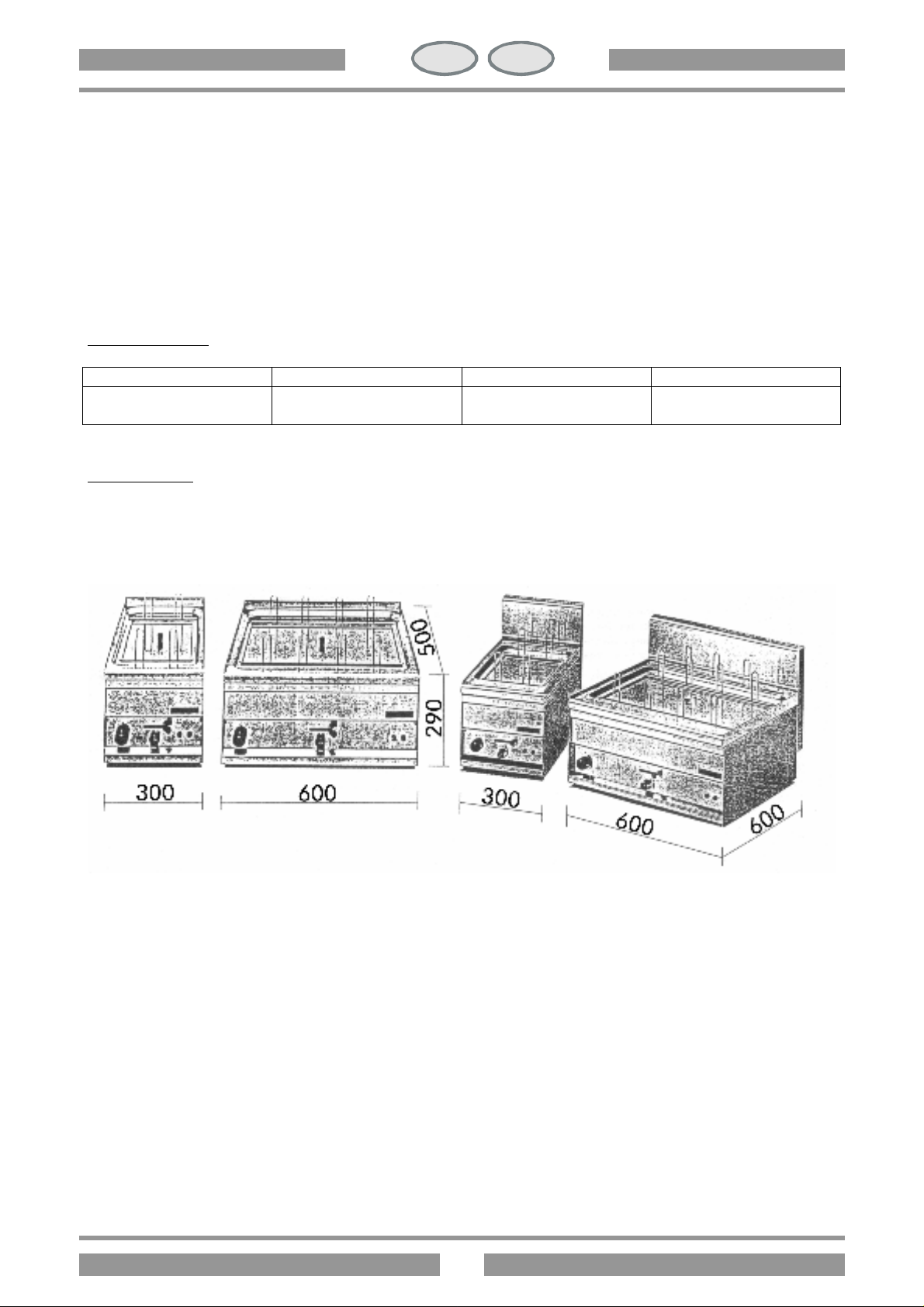
DIMENSIONI
CP-1EM CP-2ET CP -61EM CP-62ET
Page 5
5
IT
CH
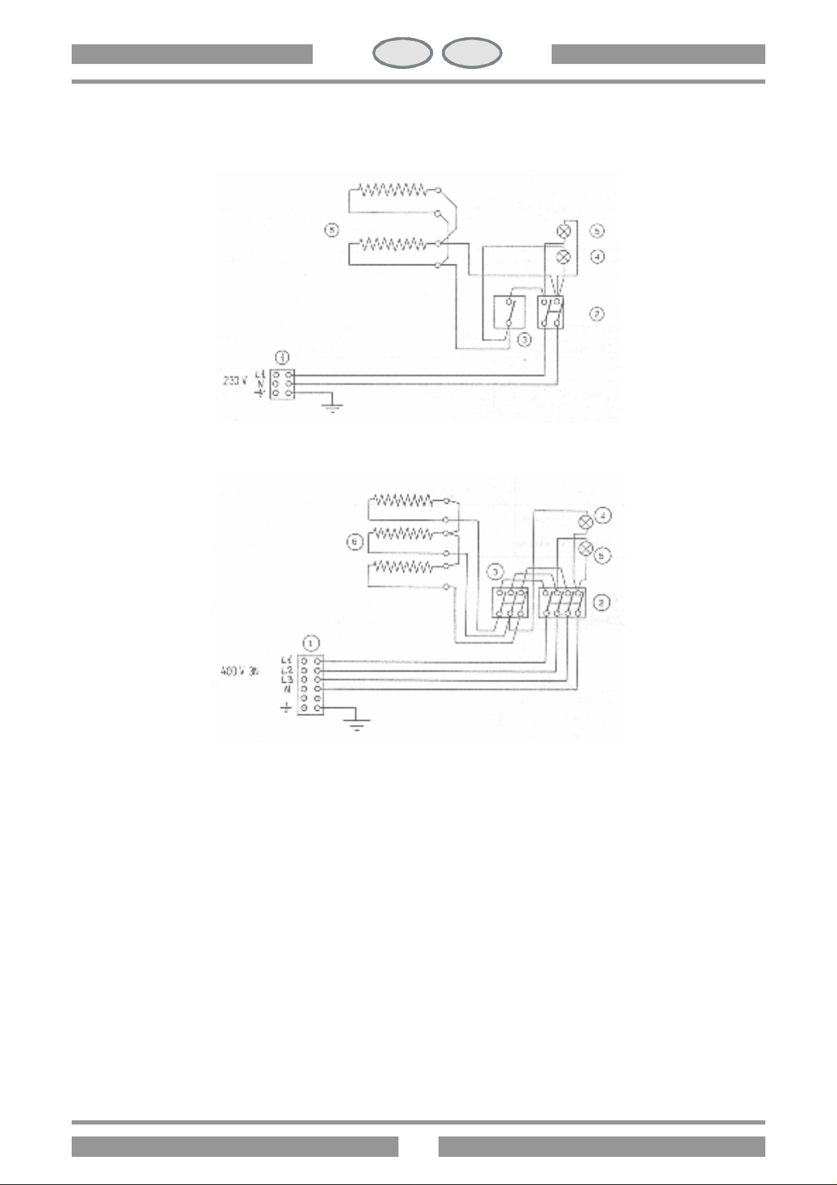
1. Morsetteria arrivo linea
4. Lampada spia bianca
SCHEMA ELETTRICO
CP-1EM
CP-61EM
CP-2ET
CP-62ET
2. Commutatore
3. Termostato
5. Lampada spia verde
6. Resistenza
MESSA IN OPERA
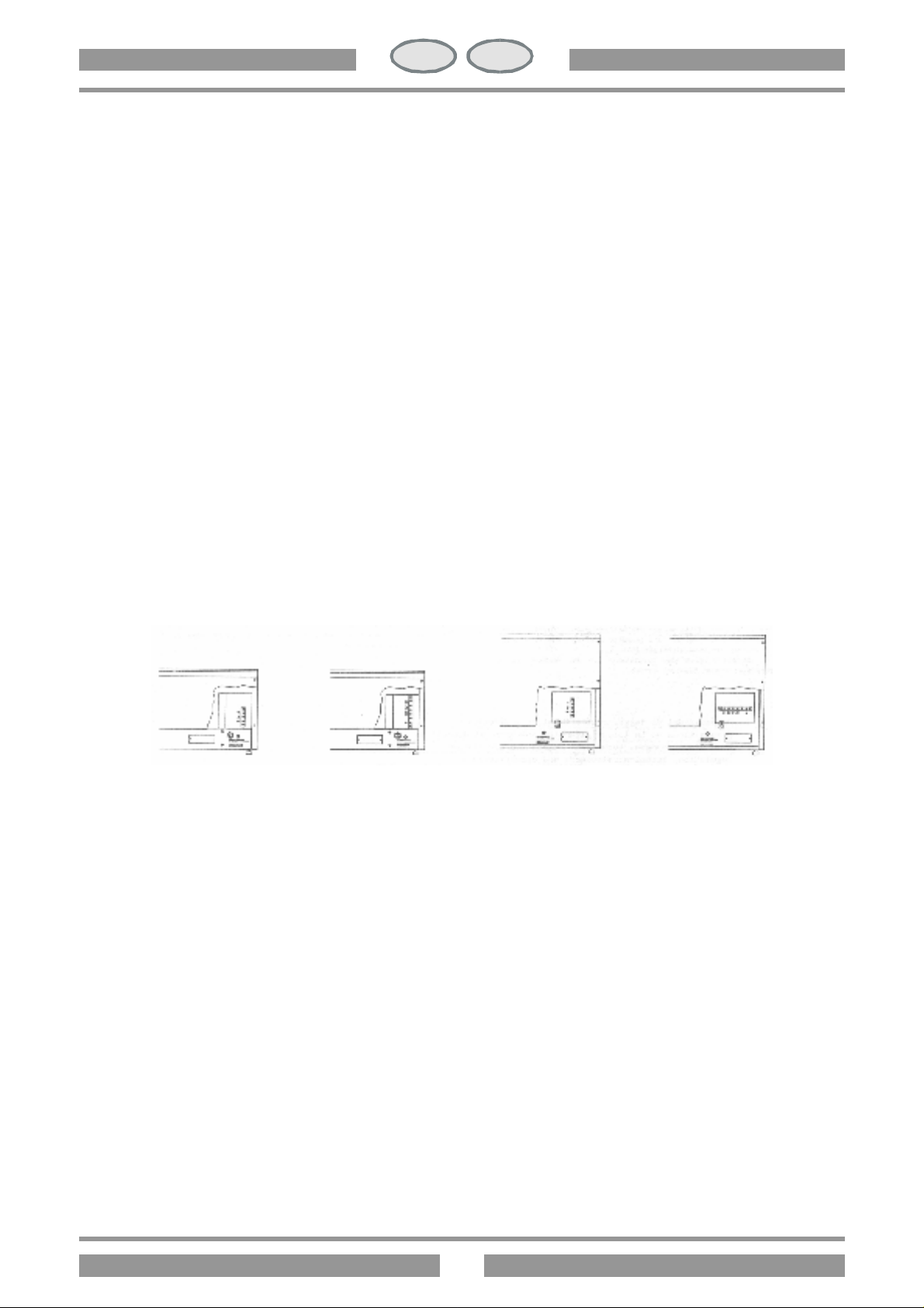
Durante il posizionamento l’apparecchio deve essere messo a bolla, piccoli dislivelli possono essere aggiustati
mediante i piedini regolabili (avvitare o svitare). L’interruttore generale o la presa devono essere nelle vicinanze
dell’apparecchio e facilmente accessibili. Si consiglia di porre l’apparecchio sotto una cappa aspirante, in modo
che l’evacuazione dei vapori avvenga in modo rapido. Qualora l’apparecchio venisse posizionato vicino a pareti,
pareti divisorie, mobili da cucina, rivestimenti decorativi ecc., si consiglia che questi siano di materiale non
infiammabile, altrimenti provvedere a rivestire tali parti con del materiale non infiammabile. Si deve anzitutto
assicurare che le prescrizioni antincendio vengano rispettate. Durante la messa in opera si deve rispettare una
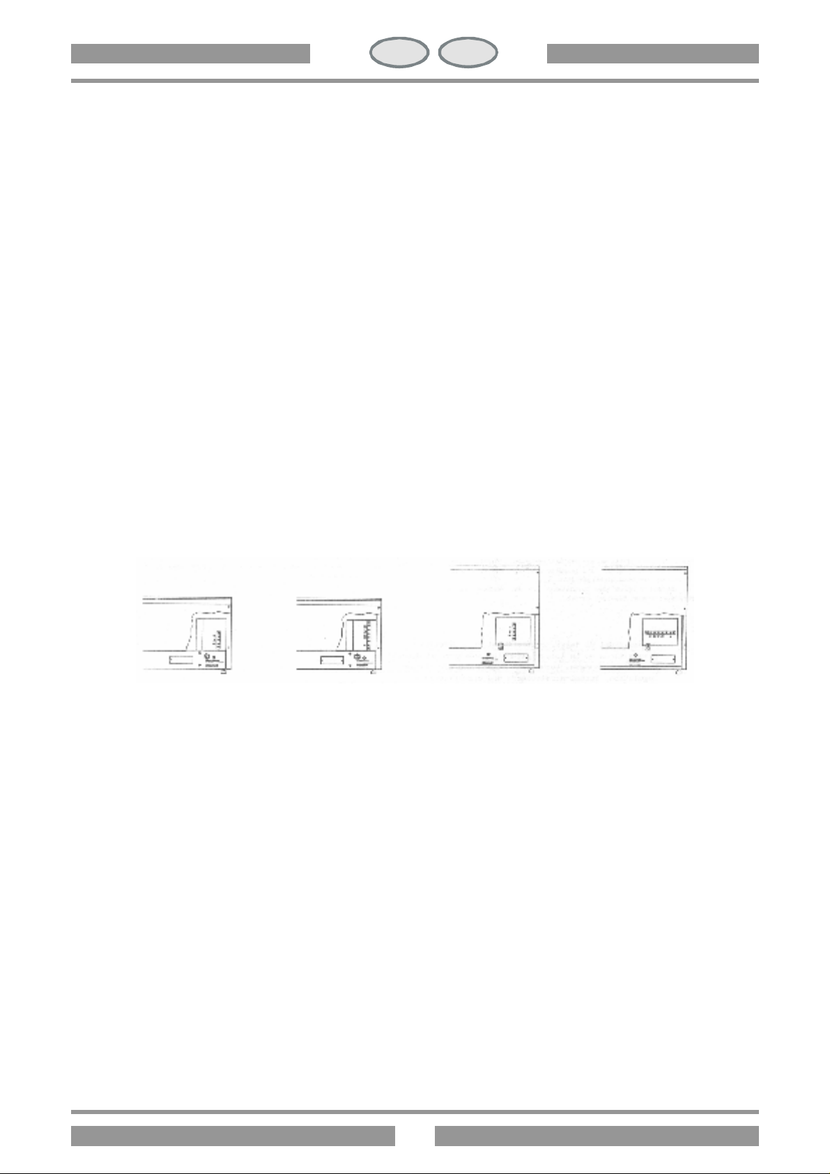
distanza massima tra il bordo anteriore del mobile-supporto e l’apparecchio.
Page 6
6
IT
CH
DISPOSIZIONI DI LEGGE, REGOLE TECNICHE E DIRETTIVE
L’installazione deve essere eseguita in osservanza delle seguenti norme:
? prescrizione antinfortunistica vigente;
? prescrizione VDE vigente.
INSTALLAZIONE
L’installazione, messa in funzione e manutenzione dell’apparecchio devono essere eseguite da personale
qualificato. Tutti i lavori necessari all’installazione devono essere eseguiti in osservanza alle norme vigenti. Il
costruttore declina qualsiasi responsabilità in caso di cattivo funzionamento, che risulta dovuto ad una installazione
errata e non conforme.
Attenzione: come da disposizioni internazionali, durante l’allacciamento dell’apparecchio è da prevedere a monte
dello stesso un dispositivo che permetta di staccare in modo onnipolarel’apparecchio dalla rete. Questo dispositivo
deve avere un’apertura dei contatti di almeno 3 mm.
ALLACCIAMENTO ELETTRICO
La morsettiera d’allacciamento dell’apparecchio si trova dietro la parete posteriore. Il cavo d’allacciamento deve
avere le seguenti caratteristiche: deve essere almeno del tipo HO5 RN F ed avere una selezione adeguata
all’apparecchio (vedi punto 1.1). Passare il cavo attraverso il passacavo ed il pressacavo, collegare i conduttori nel
corrispondente morsetto della morsettiera e fissarli. Il conduttore di terra deve essere più lungo degli altri, in modo
che, in caso di rottura del fermacavo, questo si stacca dopo i cavi della tensione.
CP-1EM CP-2ET CP-61EM CP-62ET
EQUIPOTENZIALE
L’apparecchio è da collegare in un sistema equipotenziale. La vite di collegamento è posizionata sulla parete
posteriore dell’apparecchio ed è contraddistinta da un adesivo.
Attenzione: il costruttore non è responsabile, e non risarcisce in garanzia danni provocati e che sono da addebitare
ad installazioni inadeguate e non conformi alle istruzioni.
MESSA IN FUNZIONE
Prima di utilizzare l’apparecchio per la prima frittura, bisogna pulirlo con cura, soprattutto la vasca (vedi il
paragrafo “Pulizia e cura”). Controllare l’allacciamento dell’apparecchio e metterlo in funzione secondo le
istruzioni.
Page 7
7
IT
CH
ISTRUZIONI PER L’USO
Attenzione:
? Usare l’apparecchio solo sotto sorveglianza!
? Mai mettere in funzione l’apparecchio senza acqua!
ACCENSIONE
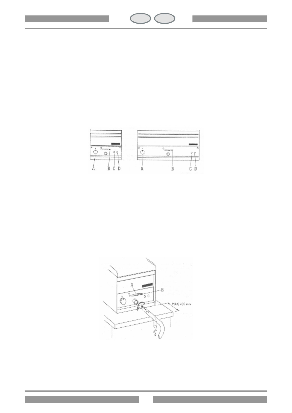
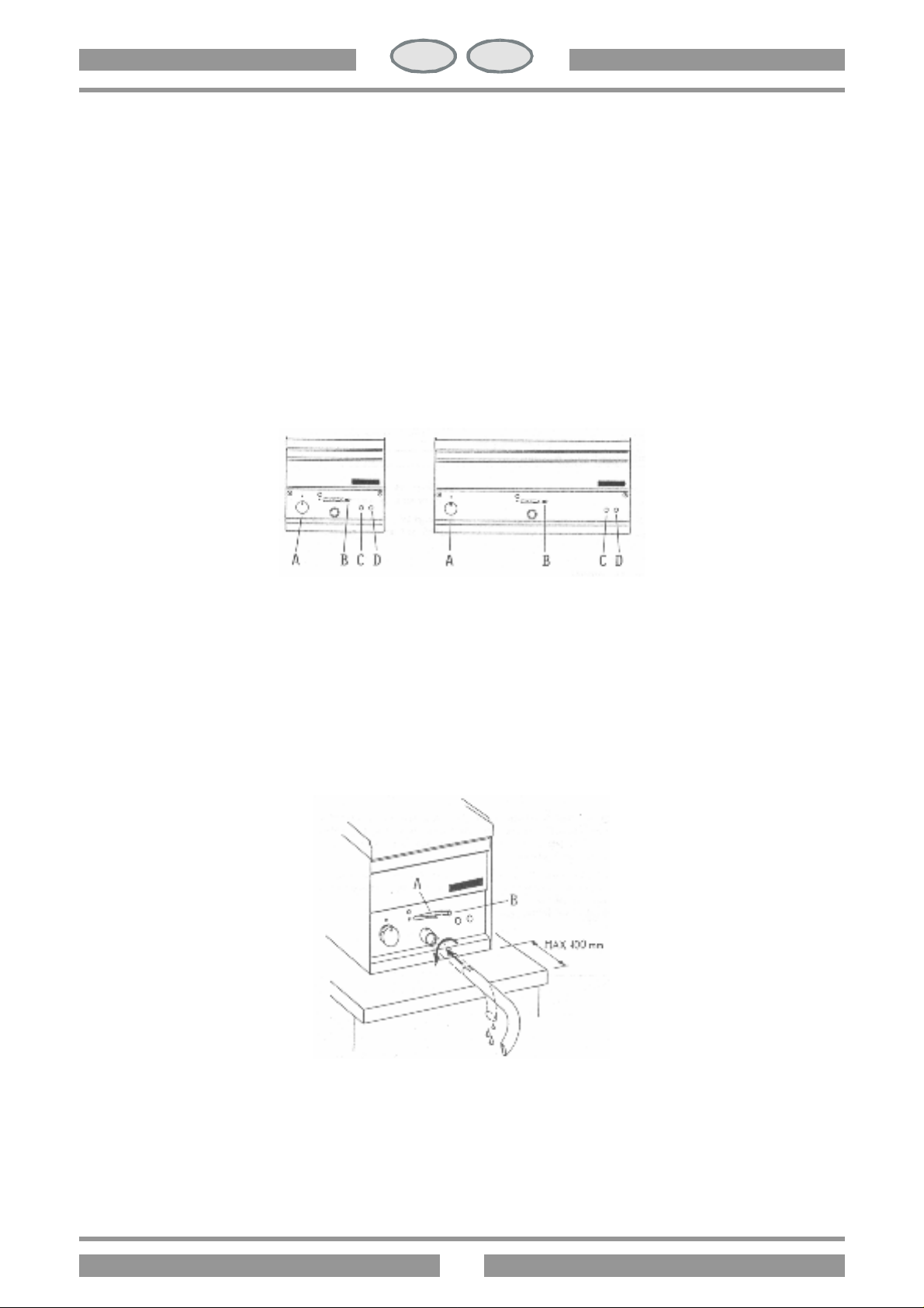
Controllare che il rubinetto d’uscita (B) sia chiuso. Riempire la vasca con acqua fino al livello massimo.
Inserire l’interruttore posto a monte dell’apparecchio. Girare la manopola (A) da (O) fino alla posizione desiderata
fra i 30°C e i 90°C, si accendono le spie (C) e (D). La lampada spia (D) indica che l’apparecchio è sotto tensione.
L’accensione della lampada spia (C) segnala il funzionamento dell’alemento riscaldante, il suo spegnimento indica
il raggiungimento della temperatura. Per spegnere l’apparecchio, rimettere la manopola (A) in posizione (O).
CP-1EM CP -2ET
CP-61EM CP-62ET
SVUOTAMENTO DELLA VASCA
L’utilizzatore è tenuto a munirsi di un contenitore adatto allo svuotamento dell’acqua. Inserire il tubo di scarico
secondo il disegno, posizionare il contenitore. Spingere il dispositivo di sicurezza contro aperture involontarie (A)
verso l’alto e portare la levetta (B) verso il punto rosso.
Importante: prestare attenzione alla distanza tra l’apparecchio e gli spigoli del supporto.
Page 8

8
IT
CH
PULIZIA E CURA
Attenzione: durante la pulizia non lavare esternamente l’apparecchio con getti d’acqua diretti o ad alta pressione!
Ogni sera a finelavoro pulire con cura l’apparecchio. La pulizia quotidiana dell’apparecchio garantisce un
funzionamento perfetto e una lunga durata dello stesso. Prima di iniziare la pulizia togliere la tensione
dall’apparecchio. Le parti in acciaio sono da lavare con acqua calda e detersivo neutro, sono poi da sciacquare
abbondantemente in modo da eliminare ogni traccia di detersivo, poi da asciugare con un panno asciutto. Non
usare detergenti abrasivi o corrosivi.
Per facilitare la pulizia si può togliere il falso fondo.
COMPORTAMENTO IN CASO DI PROLUNGATA INTERRUZIONE DI FUNZIONAMENTO
Pulire ed asciugare accuratamente l’apparecchio come da istruzioni. Togliere la tensione.
COMPORTAMENTO IN CASO DI GUASTO
In caso di guasto spegnere l’apparecchio, togliere la tensione mediante il dispositivo posto a monte
dell’apparecchio e avvisare il servizio assistenza.
MANUTENZIONE (solo per personale qualificato)
Qualsiasi lavoro di manutenzione è da far eseguire esclusivamente a personale qualificato. Prima di iniziare una
manutenzione, togliere la spina o disinserire l’interruttore posto a monte. Vuotare la vasca quando è piena.
ACCESSIBILITA’
Per accedere alla morsettiera, togliere la schiena dell’apparecchio. Per accedere al termostato, al
misìcrointerruttore di sicurezza e al collegamento delle resistenze bisogna alzare il gruppo delle resistenze e togliere
la paratia posteriore. Gli elementi di comando si raggiungono dal cruscotto anteriore, togliere il cappuccio nero
della leva dell’uscita dell’olio, svitare le viti che fissano il cruscotto e togliere quest’ultimo.
Page 9

9
IT
DE AT
CH
CH
INHALTSVERZEICHNIS
AUFSTELLUNGSANWEISUNG ........................................................................................................... 10
ANGABEN ZUM GERÄT UND SCHEMATISCHE DARSTELLUNG ........................................................... 10
SCHALTPLAN ................................................................................................................................... 11
AUFSTELLUNG ................................................................................................................................. 11
RECHTSVERORDNUNGEN, TECHNISCHE REGELN UND RICHTLINIEN................................................ 12
INSTALLATION ................................................................................................................................. 12
ELEKTROANSCHLUSS ....................................................................................................................... 12
POTENTIALAUSLEICH ....................................................................................................................... 12
INBETRIEBNAHME ............................................................................................................................ 13
BETRIEBSANWEISUNG ...................................................................................................................... 13
INBETRIEBSETZUNG ......................................................................................................................... 13
ENTLEERUNG DES BECKENS ............................................................................................................ 13
REINIGUNG UND PFLEGE ................................................................................................................ 14
VERHALTEN BEI LÄNGEREN AUSSERBETRIEBSETZUNGEN ................................................................... 14
VERHALTEN IM STORFALL ................................................................................................................. 14
WARTUNG (NUR FÜR FACHPERSONAL)............................................................................................. 14
ZUGÄNGLICHKEIT ........................................................................................................................... 14
Page 10
10
IT
DE AT
CH
CH
AUFSTELLUNGSANWEISUNG
ANGABEN ZUM GERAT UND SCHEMATISCHE DARSTELLUNG
Das Tipenschild befindet sich hinten an der Ruckward (siehe Zeichnungmim Punkt Elektroanschluss) und es
beinhaltet alle zur Installation erforderlichen Daten.
Achtung! : Gemäß den internationalen Bestimmungen muss während des Anschließens des Geräts oberhalb
desselben eine automatische Vorrichtung mit einer Kontaktöffnungsweite von mindestens 3 m installiert werden,
durch welche das Gerät auf allpolige Weise vom Stromnetz getrennt werden kann.
ELEKTRISCHE DATEN
Gerätetyp Stromspannung Gesamtanschlusswert Anschlusskabel Querschnitt
CP-1EM CP-61EM
CP-2ET CP-62ET
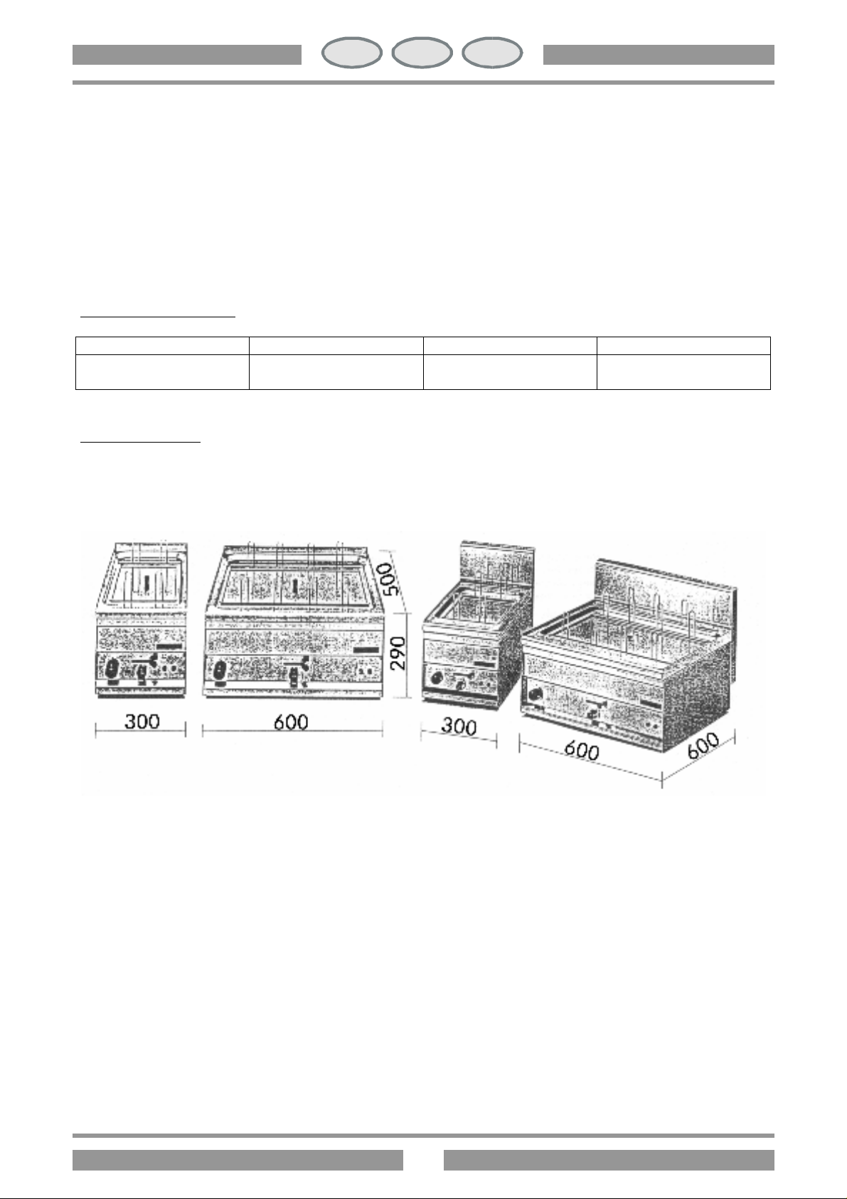
ABMESSUNGEN
CP-1EM CP-2ET CP -61EM CP-62ET
230 V
400 V 3N AC
2,823 KW
6 KW
3x1,5 mm2
5x1 mm2
Page 11
11
IT
DE AT
CH
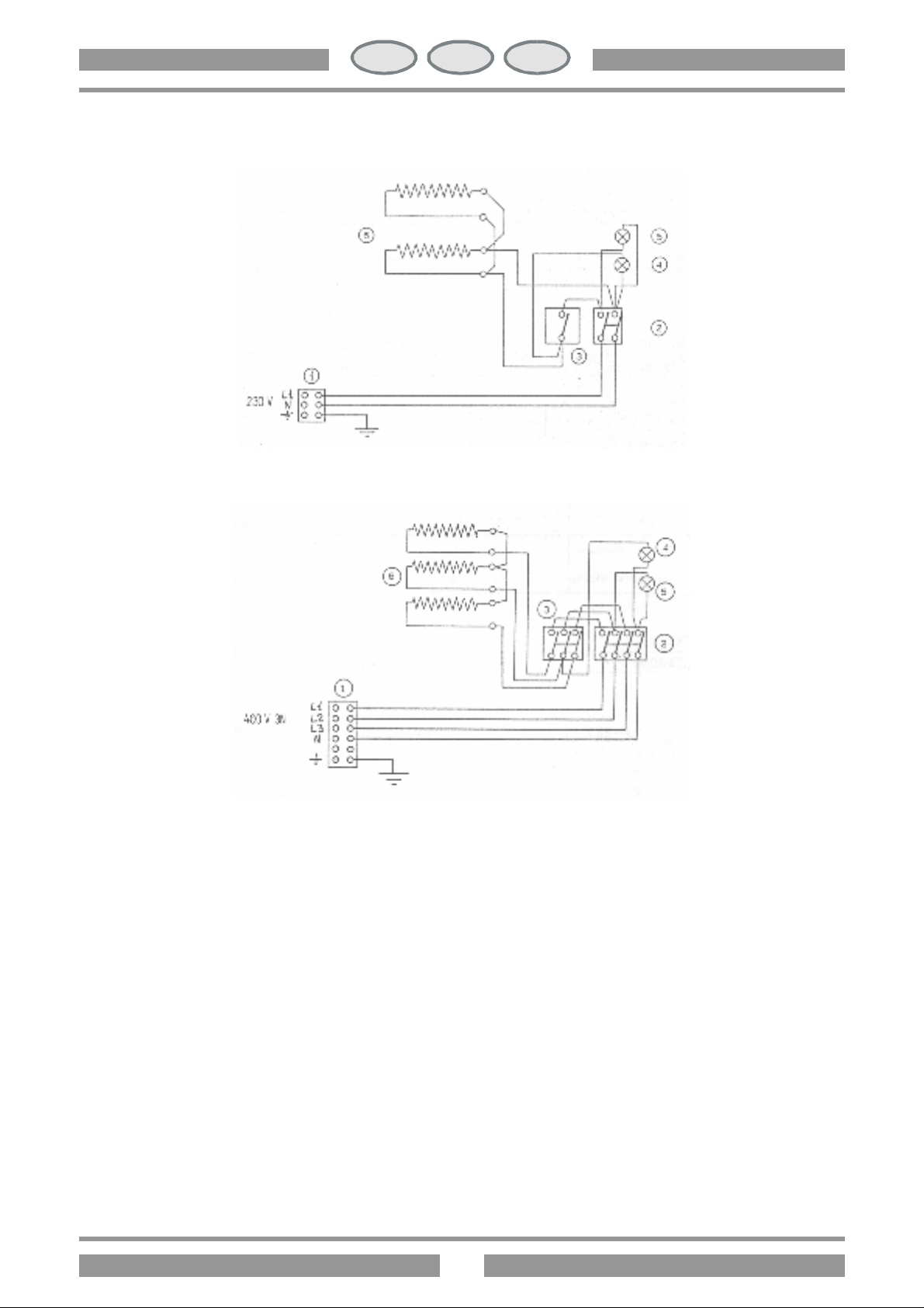
1. Ansclussbrett
SCHALTPLAN
CH
CP-1EM
CP-61EM
CP-2ET
CP-62ET
2. Schalter
3. Thermostat
4. Wei?e Kontrollampe
5. Grune Kontrollampe
6. Heinzkorper
AUFSTELLUNG
Das Gerät muss bei der Aufstellung waagerecht stehen, kleinere Unebenheiten können mit den höhenverstellbaren
Füssen des Gerätes (ein- bzw. ausschrauben) ausgeglichten werden. Hauptschalter bzw. Steckdose sollten sich in
der Nähe des Gerätes befinden und leicht zugänglich sein. Es wird empfohlen das Gerät unter einer Abzugshaube
aufzustellen, damit eine schnelle Wrasenabführung sichergestellt wird. Bei Aufstellung dieses Gerätes in
unmittelbarer Nähe von Wänden, Trennwänden, Küchenmöbel, dekorativen Verkleidungen usw. Wird empfohlen,
dass diese aus nichtbrennbarem Material gefertigt sind, andernfalls mssen sie mit geeignetem, nichtbrennbarem
Material verkleidet werden. Die genauste Beachtung der Vorschriften des Brandschutzes muss sichergestellt sein. Ein
max. Abstand zwischen der Gerätekante und der vorderen Kante des Untergestells muss werden.
Page 12
12
IT
DE AT
CH
CH
RECHTSVERORDNUNGEN, TECHNISCHE REGELN UND RICHTLINEN
Bei der Aufstellung sind folgende geltende Vorschriften zu beachten :
? einschlägige Unfallverhütungsvorschriften ;
? einschlägige VDE-Vorschriften.
INSTALLATION
Installation, Inbetriebnahme und Wartung des Gerätes müssen durch sachkundiges Personal durchgeführt werden.
Sämtliche Installationsarbeiten müssen unter Beachtung der gültigen Vorschriften ausgeführt werden. Der Hersteller
lehnt jegliche Verantwortung ab, die auf eine schlechte Funktion duch fehlhafte oder unsachgemässe Installation
zurckzuführen ist.
Bemerkung: Laut internationalen Vorschriften ist beim Anschluss des Gerätes eine Einrichtung vorzusehen, die es
ermöglicht, das Gerät mit einer Kontakt-Offnungsweite von mindestens 3 mm allpolig vom Netz zu trennen. Als
geeignete Trennvorrichtungen gelten LS-Schalter, Sicherungen und Schütze.
ELEKTROANSCHLUSS
Die Anschlussklemme des Gerätes befindet sich hinter der Rückwand. Die Anschlussleitung muss mindestens vom
Typ HO5 RN F sein und einem, dem Gerät entsprechend mindest Querschnitt haben (siehe Punkt 1.1).
Kabel durch die Einfhrung und Zugentlastungstecken, die einzelnen Drähte entsprechend der jeweiligen Schaltung
an der Anschlussklemme befestigen. Der Schutzleiter muss so lang sein, dass er beim Versagen der Zugentlastung
erst nach den stromführenden Adern des Anschlusskabels auf Zug beansprucht werden kann.
CP-1EM CP-2ET CP-61EM CP-62ET
POTENTIALAUSLEICH
Das Gerät ist in einem Potentialausleichsystem einzubeziehen. Hierzu befindet sich die Anschlußschraube auf der
Rückwand und ist mit einem Aufkleber gekennzeichnet.
Bemerkung: der Hersteller übernimmt keine Haftung bzw. Garantierverpflichtungen für Schäden die durch
Nichtbeachtung der Vorschriften oder unsachgemässe Installation zurückzuführen sind.
Page 13
13
IT
DE AT
CH
CH
INBETRIEBNAHME
Vor dem ersten Fritieren empfehlen wir das Gerät sorgfältig zu reinigen, insbesondere das Fritierbecken (siehe
Abschnitt "Reinigung und Pflege"). Installation überprüfen und das Gerät gemäss der Anweisung in Betrieb setzen.
CP-1EM CP -2ET
CP-61EM CP -62ET
BETRIEBSANWEISUNG
Achtung:
? Gerät nur für beaufsichtigten Betrieb !
? Das Gerät darf nie trocken laufen !
INBETRIEBSETZUNG
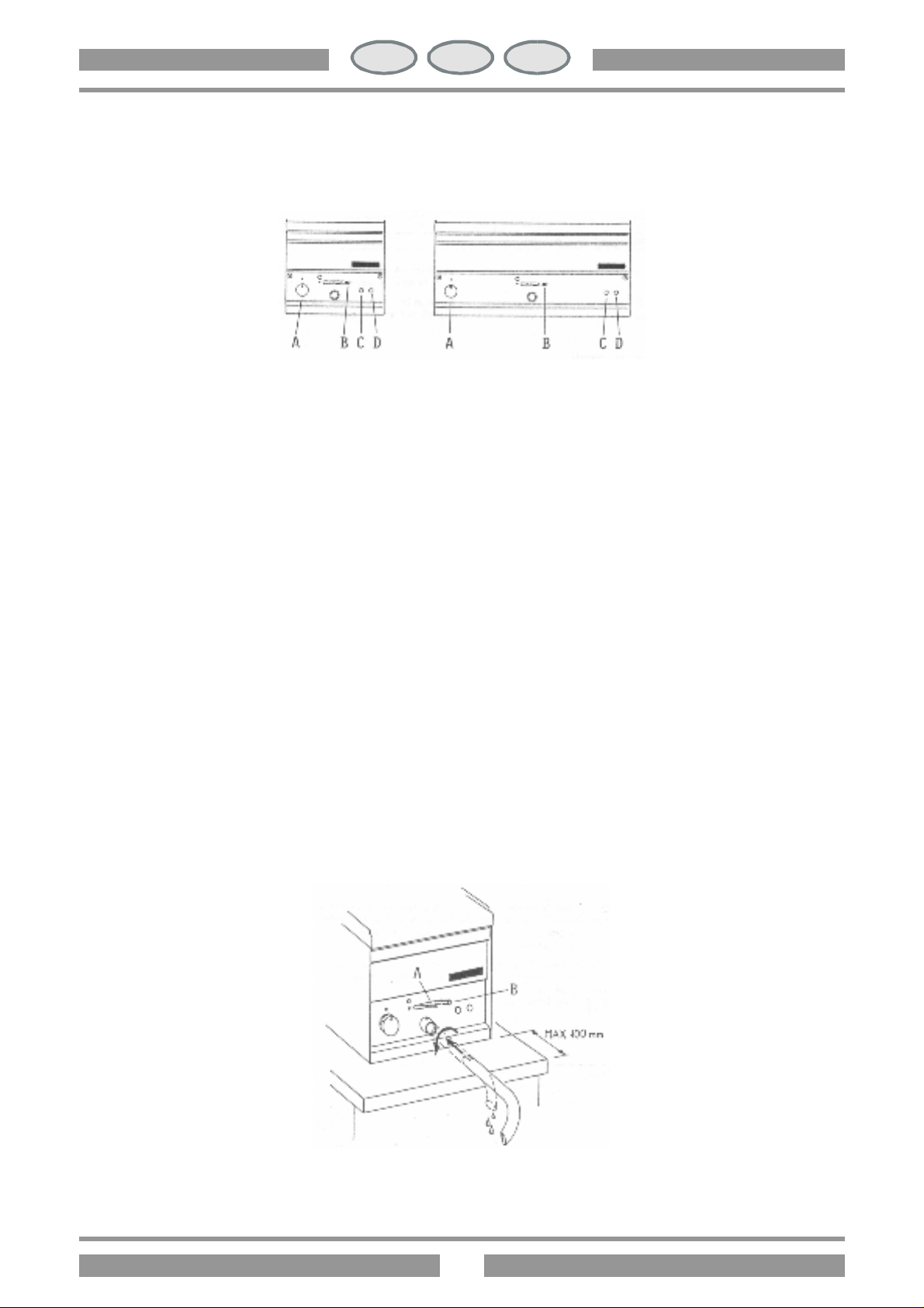
Überprufen das der Ölauslass (B) geschlossen ist. Das becken bis zur eingestanzten Markierung mit Öl auffüllen.
Bauseits installierter Hauptschalter einschalten. Gerätschalter (A) von (O) auf die gewünschte Position von 30°C bis
90°C drehen, die Signalleuchten (C) und (D) leuchten. Die Leuchte (C) zeigt an, dass das Geräte unte Strom steht,
die Leucht (C) zeigt an, dass die Heizelemente in Betrieb sind, sobald die Temperatur erreicht ist, erlischt diese
Leuchte (C). Zum Ausschalten des Gerätes, Geräteschalter (A) auf Position (O) drehen.
ENTLEERUNG DES BECKENS
Der Benutzen soll dafür Sorgen, dass für den Wasserauslass ein entsprechender Behälter zur Verfügung steht.
Ausslassrohr gemäss der Zeichnung anbringen, Berhälter darunter stellen. Sicherheitseinrichtung (A) hochschieben
und den Auslasshebel (B) in Richtung des roten Punktes betätigen.
Wichting: Beachten Sie bitte den Abstand zur Kante des Untergestells.
Page 14

14
IT
DE AT
CH
CH
REINUNG UND PFLEGE
Bemerkung: Das Gerät darf bei der Reinung von aussen weder mit einem direkten Wasserstrahl noch mit einem
Hochdruckreiniger abgespritzt werden !
Jeden Abend nach Betrieb sende muss das Gerät sorgfältig gereinigt werden. Die tägliche Reinigung des Gerätes
gewährleistet die einwandfreie Funktion und eine lange Lebensdauer. Bevor manmit dem Reinigung des beginnt,
muss man das Gerät stromlos machen. Edelstahlteide sind mit warmem Wasser und einem milden Reinigungsmittel
zu reinigen. Es soll dann eine gründliche Spülung erfolgen, so dass alle Spülmittelreste entfernt werden mit einem
Lappen abtrockenen. Keine groben oder korrosiven Reinigungsmittel verwenden, denn dadurch könnten
Edelstehlteile beschädigt werden. Der Blindboden kann zur Reinigung herausgenommen werden.
VERHALTEN BEI LÄNGEREN AUSSERBETRIEBSETZUNGEN
Das Gerät nach Anleitung gründlich reinigen und abtrocknen, Stromzufuhr schliessen bzw. ausschalten.
VERHALTEN IM STÖRFALL
Im Störall sollte das Gerät ausserbetrieb gesetzt werden. Kundendienst benachrichtigen.
WARTUNG (Nur für Fachpersonal)
Wartungsarbeiten sind ausschliesslich von einem Fachmann durchzufüren. Bevor legliche Arbeit angetangen wird,
den Stecker aus der Steckdose bzw. Sicherung herausnehmen. Wenn erforderlich Becken entleeren.
ZUGÄNGLICHKEIT
Un an die Anschlussklemme zu gelangen, Rückwand des Gerätes abnehmen. Um an den Thermostaten, den
Sicherheits-Mikroschalter und dem Anschluss der Heizelemente zu gelangen muss man die Heizelementengruppe
heben und die Rückwand der Gruppe abnehmen. Um an die Bedienungsteile zu gelangen, schwarzes Kunsttoffteil
des Olauslassknebels abschrauben, Bedienungsblende abnehmen, im dem man die Befestigungsschrauben
abschraubt.
Page 15

15
IT
FR
BE
CH
INDEX
INSTRUCTIONS POUR L’INSTALLATION ....................................................................................................16
DONNEÉS TECHMIQUES ET REPRÉSENTATION SCHÉMATIQUE ................................................................16
SCHEMA ÉLETRIQUE ................................................................................................................................17
MISE EN OEUVRE .....................................................................................................................................17
DISPOSITION DE LA LOI, RÉGLEMENTS TECHNIQUES ET DIRECTIVES ........................................................18
INSTALLATION .........................................................................................................................................18
RACCORDEMENT ÉLECTRIQUE ................................................................................................................18
EQUIPOTENTIEL ......................................................................................................................................18
MISE AN SERVICE .....................................................................................................................................18
MODE D’EMPLOI .....................................................................................................................................19
ALLUMAGE ..............................................................................................................................................19
VIDANGE DE LA CUVE .............................................................................................................................19
NETTOYAGE ET SOIN ..............................................................................................................................20
COMPORTEMENT EN CAS D’ARRÊT DE FUNCTIONNEMENT PROLONGÉ .................................................20
COMPORTEMENT EN CAS DE PANNE ......................................................................................................20
ENTRETIEN (RÉSERVÉ AU PERSONNEL QUALIFIÉ) .......................................................................................20
ACCESSIBILITÉ .........................................................................................................................................20
Page 16
16
IT
FR
BE
CH
INSTRUCTIONS PUOR L’INSTALLATION
DONNÉES TECHNIQUES ET REPRÉSENTATION SCHÉMATIQUE
La plaque de matricule se trouve sur la paroi postérieure (voir la figure, a la connexion electrique) et contient toutes
les données nécessaires pour la connexion.
DONNÉES ELECTRIQUES
Modéles Alimentation Charge max Vis de connexion
CP-1EM CP-61EM
CP-2ET CP-62ET
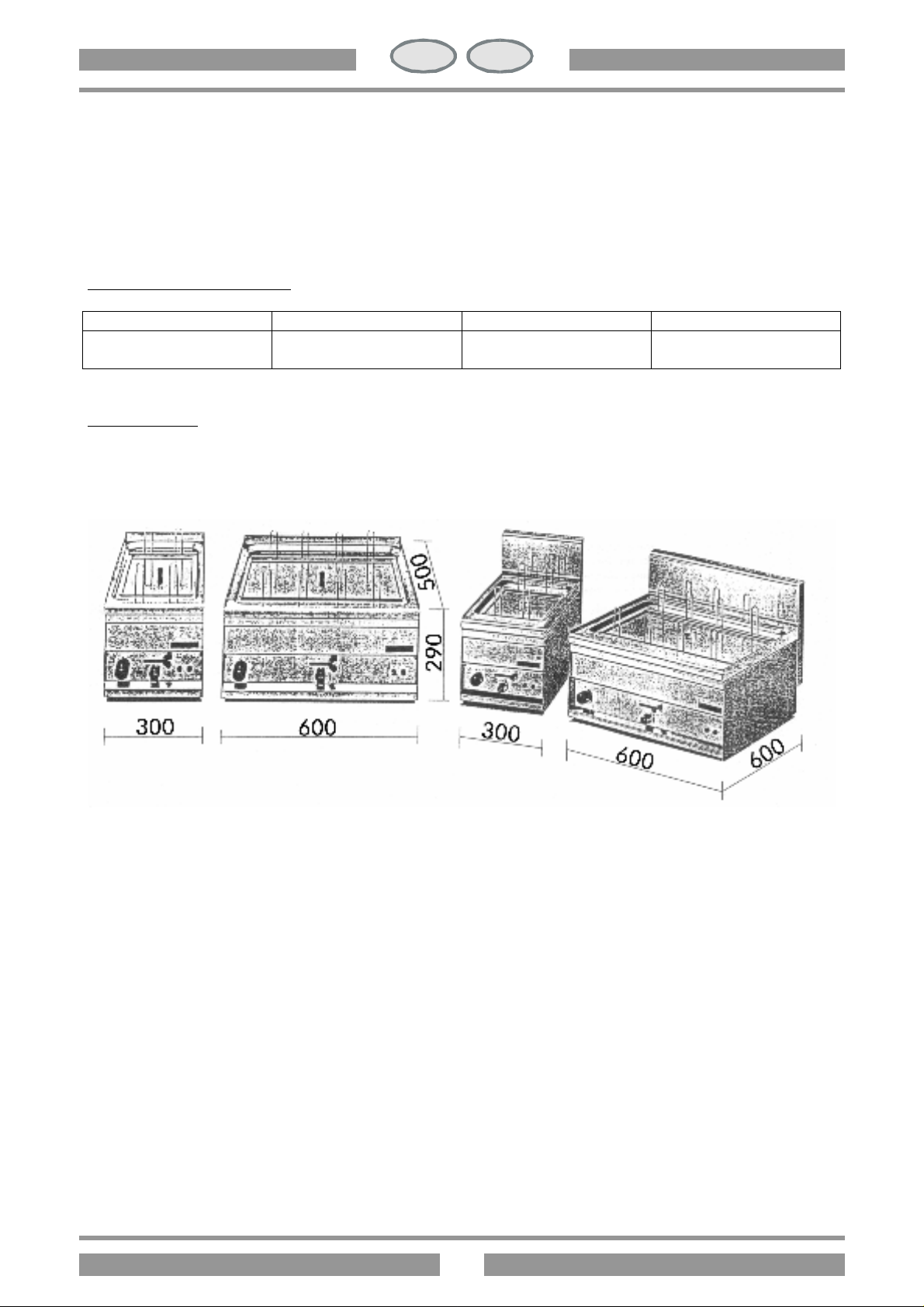
DIMENSIONS
CP-1EM CP-2ET CP -61EM CP-62ET
230 V
400 V 3N AC
2,823 KW
6 KW
3x1,5 mm2
5x1 mm2
Page 17
17
IT
FR
BE
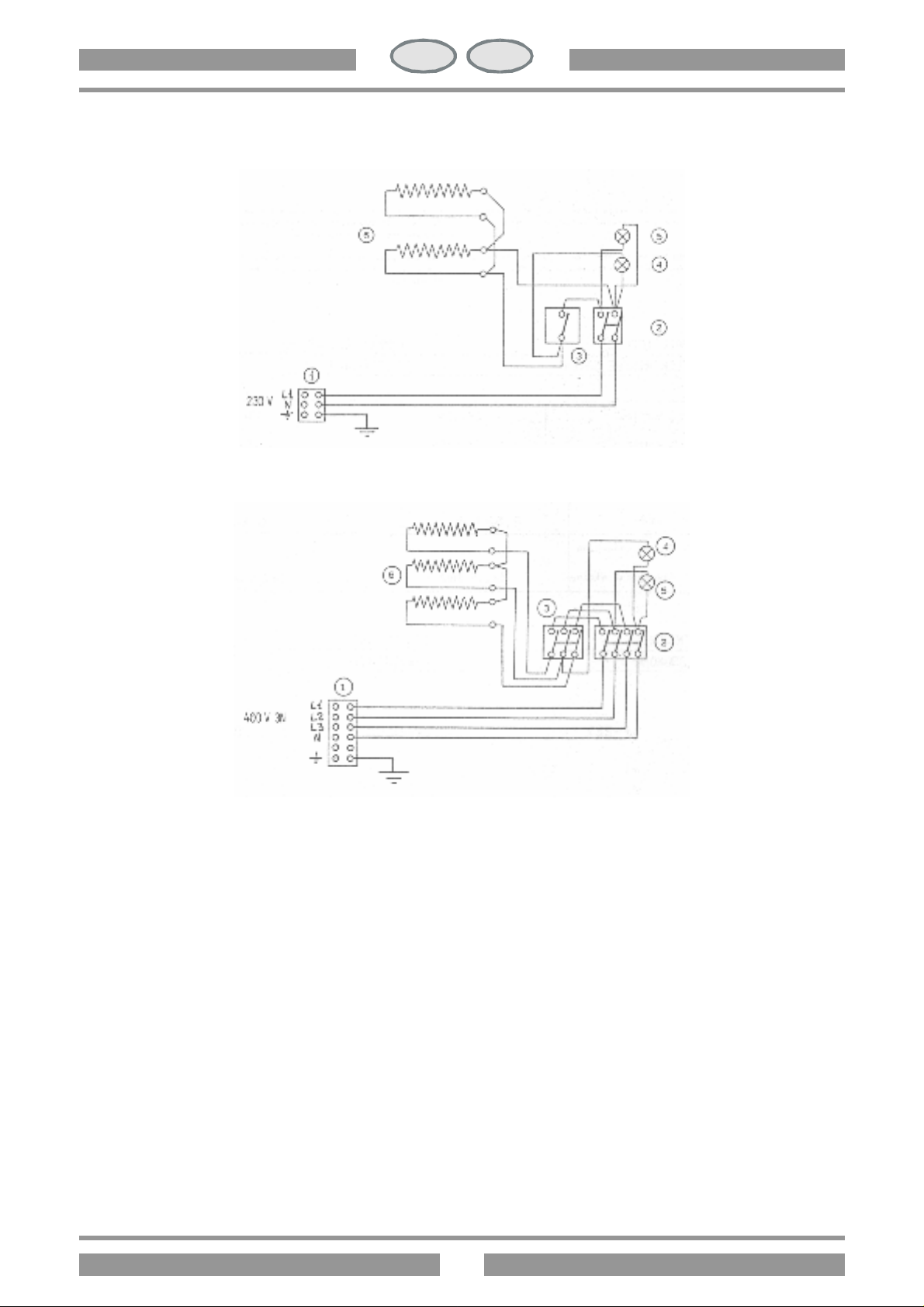
1. Bornes arrivee lign
4. Lampe temoil blanc
SCHEMA ÉLECTRIQUE
CH
CP-1EM
CP-61EM
CP-2ET
CP-62ET
2. Commutateur
3. Thermostat
5. Lampe temoil vert
6. Resistence
MISE EN OEUVRE
Pendant la mise en place il faut vérifier le niveau à bulle d’air de l’appareil. Les petites différences de niveau
peuvent être ajustées au moyen des pieds-de biche réglables (visser ou dévisser). L’interrupteur général et la prise
de courant doivent être placés en proximité de l’appareil et facilment accessible. On conseille de mettre l’appareil
sous une hotte d’aspiration, pour l’évacuation rapide des vapeurs. Au cas où l’appareil serait placé près de parois,
cloisons, meubles de cuisine, revétements écoratifs, etc., ceux-ci devraient être en matériel non inflammable, dans
le cas contraire revêtir ces parties avec du matériel non inflammable. Il faut en tout premier lieu s’assurer que les
prescriptions contre les incendies soient respectées. Au cours de la mise en oeuvre il faut respecter une distance
maximale entre le bord antérieur du meuble de support et l’appareil.
Page 18
18
IT
FR
BE
CH
DISPOSITIONS DE LA LOI, RÉGLEMENTS TECHNIQUES ET DIRECTIVES
Pour l’installation il faut se conformer aux réglements suivant :
? prescription en vigueur pour la prévention des accidents ;
? prescription VDE en vigueur.
INSTALLATION
L’installation, la mis en service et l’entretien de l’appareil doivent être effectués seulment par le personnel qualifé.
Tous les travaux nécessaires pour l’installation doivent être effectués conformément aux reglements en vigueur. Le
fabricant décline toute responsabilité en cas de fonctionnement incorrect, résultant de l’installation incorrecte ou
non conforme.
Attention: Conformément aux dispositions internationales, lorsqu’on effectue le branchement électrique de
l’appareil il faut placer au-dessus de celui-ci un dispositif du réseau ; ce dispositif doit avoir une ouverture des
contacts d’au moins 3 mm.
RACCORDEMENT ÉLECTRIQUE
La serre-câble de l’appareil se trouve derrièr la paroi postérieure. Le cordon de rallonge doit avoir les
caractéristiques suivantes: il doit être du type HO5 RN F et avoir une section appropriée à l’appareil (voir point
1.1). Passer le cordon dans la gaine spéciale et le dispositif serre-fils et brancher les deux conducteurs à la borne
correspondante du serre-câble en les fixant. Le conducteur de prise de terre doit être plus long que les autres, de
façon qu’en cas de rapture du serre-fils on pisse le débrancher après les câbles de la tension.
CP-1EM CP-2ET CP-61EM CP-62ET
EQUIPOTENTIEL
Il faut brancher l’appareil à un système équipotentiel. La vis de connexion se trouve sur la paroi postérieur de
l’appareil et est marquée d’un adhésif.
Attention: le fabricant m’est pas responsable et n’indemnise pas les domages provoqués ou qui sont la
conséquence directe d’installations incorrectes ou non conformes aux instructions.
MISE EN SERVICE
Avant d’utiliser l’appareil pour la prémiere friture il faut le nettoyer soigneusement, nettoyer en particulier la cuve
(voir paragraphe "Nettoyage et soin"). Contrôler le brachement de l’appareil et le mettre en service suivant les
instructions.
Page 19
19
IT
FR
BE
CH
MODE D’EMPLOI
Attention:
? N’utiliser l’appareil que sous surveillance !
? Il ne faut jamais mettre en service l’appareil sans eau !
ALLUMAGE
S’assurer que le robinet de sortie de l’huile (B) soit fermé. Remplir la cuve avec de l’huile jusqu’à la limite maximum.
Brancher l’interrupteur placé au-dessus de l’appareil. Tourner la manette (A) de (O) jusqu’à la position voulue entre
30°C et 90°C les lampes témoin (C) et (D) s’allument. La lampe témoin (D) indique que l’appareil ast en marche.
Lorsque la lampe témoin (C) s’allume elle indique que l’élement chauffant est en marche, elle s’éteint lorsque la
temperature est atteinte. Pour éteindre l’appareil reporter la manette (A) sur la position (O).
CP-1EM CP -2ET
CP-61EM CP-62ET
VIDANGE DE LA CUVE
L’usager doit se munir d’un récipient adapté à la vidange de la cuve. Brancher le tuyau de décharge selon la figure,
placer le récipient dans la position convenable. Pour éviter toute ouverture involontaire, pousser le dispositif de sûreté (A)
vers le haut et pousser le levier (B) vers le point rouge.
Important: respecter la distance entre l’appareil et les coins du support.
Page 20

20
IT
FR
BE
CH
NETTOYAGE ET SOIN
Attention: Pendant la nettoyage il ne faut pas laver l’appareil à l’extérieur avec des jets d’eau directs à haute pression.
Chaque soir à la fin du travail nettoyer soigneusement l’appareil. Le nettoyage quotidien de l’appareil garantitmle
functionnement parfait et la longue durée de l’appareil. Avant de commencer le nettoyage debrancher l’appareil.
Laver les parties en acier avec de l’eau chaude et du détergent neutre, ensuite il faut les rincer abondamment de
façon à l’éliminer toute trace de détergent et les essuyer enfin avec un tissu. N’employer aucun produit abrasif ou
corrosif. Pour faciliter le nettoyage, on peut enlever le doble fond.
COMPORTEMENT EN CAS D’ARRÊT DE FUNCTIONNEMENT PROLONGÉ
Nettoyer et essuyer soigneusement l’appareil selon les insructions, interrompre le courrant.
COMPORTEMENT EN CAS DE PANNE
En cas de panne éteindre l’appareil, interrompre le courant à l’aide du dispositif placé au-dessus de l’appareil et
prévenir le service d’assistance.
ENTRETIEN (reservé au personnel qualifié)
Tout travail d’entretien ne doit être effectué que par le personnel qualifié. Avant de commencer un entretien,
débrancher la fiche de prise de courant ou l’interrupteur se trouvant au-dessus. Vider la cuve s’elle est pleine.
ACCESSIBILITÉ
Pour accéder au serre-câble, enlever le dos de l’appareil. Pour accéder au thermostat, au microinterrupteur de
sécurité et à la connexion des résistances lever le groupe des résistances et enlever la cloison postérieure. On
atteint les éléments de commande du tableau de bord antérieur, enlever le capuchon noir du lavier de sortie de
l’huile dévisser les vis qui fixent le tableau de bord en les enlevant.
Page 21

21
IT
GB
IE
CH
INDEX
INSTRUCTIONS FOR INSTALLATION ................................................................................................. 22
TECHNICAL DATA AND DRAWINGS ................................................................................................. 22
ELECTRICAL DIAGRAM ..................................................................................................................... 23
POSITIONING ................................................................................................................................. 23
REGULATIONS, TECHNICAL STANDARDS AND SPECIFICATIONS ....................................................... 24
INSTALLATION ................................................................................................................................. 24
ELECTRICAL CONNECTION ............................................................................................................. 24
EQUIPOTENTIAL .............................................................................................................................. 24
START-UP ......................................................................................................................................... 24
INSTRUCTIONS FOR USE ................................................................................................................. 24
IGNITION ........................................................................................................................................ 25
DRAINING THE FRYING PAN ............................................................................................................ 25
CLEANING AND MAINTENANCE ...................................................................................................... 25
PREPARATION FOR PROLONGED PERIOD OUT OF USE ................................................................... 25
INSTRUCTIONS IN THE EVENT OF FAULTS ........................................................................................ 26
MAINTENANCE (FOR QUALIFIED FITTERS ONLY) .............................................................................. 26
ACCESSIBILITY ................................................................................................................................. 26
Page 22
22
IT
GB
IE
CH
INSTRUCTIONS
TECHNICAL DATA AND DRAWINGS
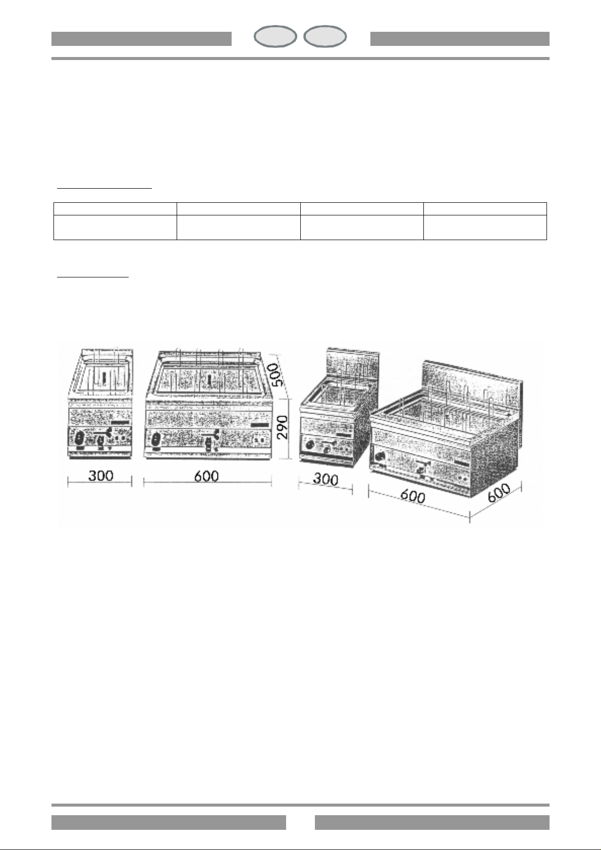
The data plate is attached to the back panel (see drawing electrical connection point) and contains all the
information necessary for connection.
ELECTRICAL DATA
Models Feed Max power Electrical wiring
CP-1EM CP-61EM
CP-2ET CP-62ET
DIMENSIONS
CP-1EM CP-2ET CP -61EM CP -62ET
230 V
400 V 3N AC
2,823 KW
6 KW
3x1,5 mm2
5x1 mm2
Page 23
23
IT
GB
IE
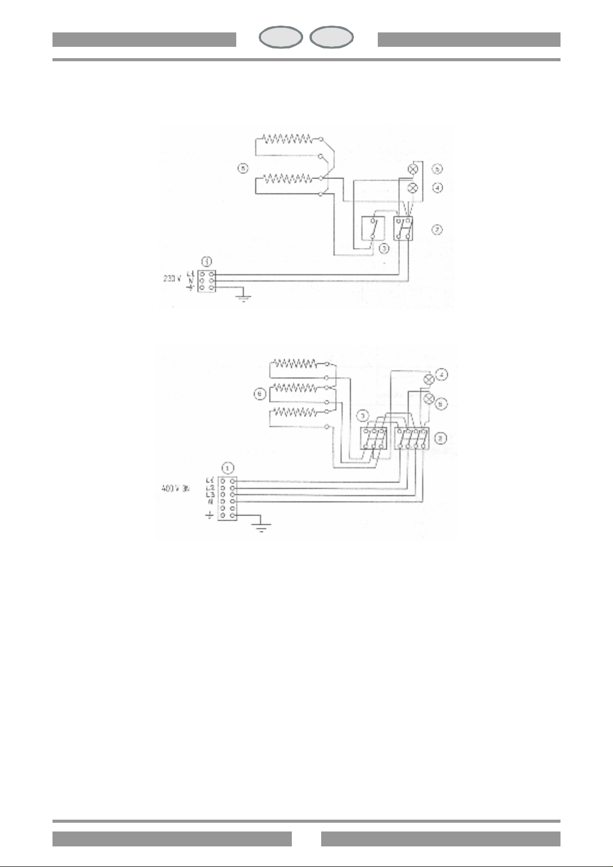
Terminal board
4. White pilot lamp
ELECTRICAL DIAGRAM
CH
CP-1EM
CP-61EM
1.
2. Swich
3. Thermostat
CP-2ET
CP-62ET
5. Green pilot lamp
6. Heating element
POSITIONING
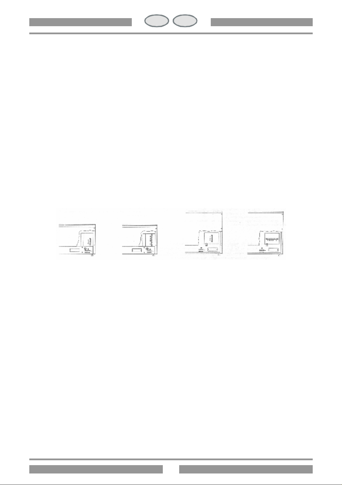
On positioning the appliance, ensure that it is perfectly levelled. Small adjustments can be made by screwing the
adjustable feet up or down. The master switch or the socket point must be in proximity to the appliance and easily
accessible. It is advisable to place the oven under an extractor hood to ensure rapid elimination of steam. If the
appliance is placed near a wall or partition, kitchen furniture or decorative coverings, etc., these must be fire-proof
or coated with fire-proofing. Local fire prevention regulations must be observed. There must be maximum clearance
between the front edge of the cabinet and the appliance.
Page 24
24
IT
GB
IE
CH
REGULATIONS, TECHNICAL STANDARDS AND SPECIFICATIONS
Installation must be carried out in accordance with:
? current accident prevention legislation;
? current VDE specifications.
INSTALLATION
The installation, start-up and maintenance of this appliance must be carried out only by qualified fitters. All
installation operations must be in accordance with current regulations. The manufacturer declines all responsibility
for malfunctioning due to bad or faulty installation.
Attention: international regulations require that a omnipole cut-out device with contact opening of at least 3 mm be
fitted on the wiring leading to the appliance.
ELECTRICAL CONNECTION
The terminal board is situated behind the back panel. The electrical wiring must be no less than HO5 RN F and
have a section suitable for the appliance (see 1.1). Secure the wiring with the wiring clips. Connect the wire ends to
their terminals on the terminal board. The earthing wire must be longer than the other wires so that it will disconnect
after the live wires in the event of the fastener breaking.
CP-1EM CP-2ET CP-61EM CP-62ET
EQUIPOTENTIAL
The appliance is designed to be connected to a unipotential system. The connecting screw is situated on the back of
the appliance and is identified by an adhesive label.
Attention: the manufacturer cannot be held responsible for, and does not cover in the guarantee any damage
resulting from bad or faulty connections.
START-UP
Before using the appliance for the first time it must be throughly cleaned, paying particular attention to the pan (see
the paragraph “Cleaning and maintenance”). Check all the connections then start the appliance as per instructions.
INSTRUCTIONS FOR USE
Attention:
? Never leave the working appliance unattended!
? Never start up the appliance without water!
Page 25
25
IT
GB
IE
CH
IGNITION
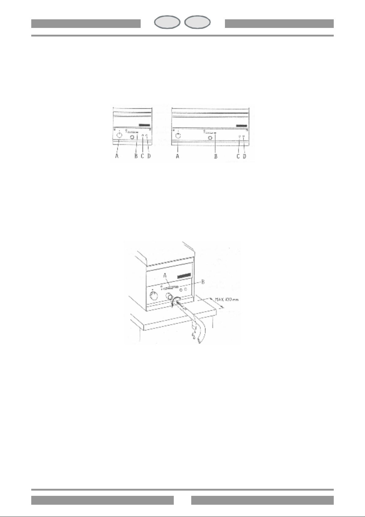
Check to ensure that the oil outlet tap (B) is turned off. Fill the pan with oil or fat up to the maximum level mark.
Switch on at the mains. Turn knob (A) from (O) to the position required between 30°C and 90°C. Warning lights (C)
and (D) will illuminate. The warning light (D) illuminates when the appliance is live. The warning light (C) illuminates
when the heating element is on. This warning light goes off when the element has reached the required
temperature. To turn off the appliance, turn knob (A) to position (O).
CP-1EM CP -2ET
CP-61EM CP-62ET
EMPTYNG THE TANK
The user should be equipped with a suitable container for the drained water. Insert the outlet pipe as shown on the
drawing and place the container in position. Push the safety device (A) upwards and move lever (B) to the red dot.
Important: pay attention to the clearance between the appliance and the edges of the stands.
CLEANING AND MAINTENANCE
Attention: when cleaning do not wash the outer casing with direct or high pressure jets of water.
At the end of each working day clean the appliance throughly. Daily cleaning ensures long life and efficiency for
your appliance. Before carrying out cleaning operations, switch off at the mains, Wash the steel parts with warm
water and neutral detergent, rinse well to eliminate all trace of the detergent, then dry with a soft cloth. Do not use
abrasive or corrosive cleaners. To facilitate cleaning the double bottom can be removed.
PREPARATION FOR A PROLONGED OUT OF USE
Throughly clean and dry the appliance as per instructions, switch off at the mains.
Page 26

26
IT
GB
IE
CH
INSTRUCTIONS IN THE EVENT OF FAULTS
If a fault develops, turn off the appliance, switch off at the mains and call the technical assistance service.
MAINTENANCE (for qualified fitters only)
Any maintenance operations must be carried out exclusively by qualified fitters. Before commencing maintenance
operations or repairs, disconnect the appliance or turn off at the mains. Empty the pan if necessary.
ACCESSIBILITY
To gain access to the terminal board remove the back panel. To gain access to the thermostat, safety microswitch
and heating element connections, raise the element unit and remove the back panel. The control mechanisms are
accessible from the front fascia. Remove the back cap on the oil outlet lever, loosen the screws securing the fascia
and remove.
Page 27
IT CH
caratteristiche, pena il totale decadimento della garanzia.
v Durezza totale compresa tra 0,5 e 5° francesi per ridurre il formarsi di calcare
v Pressione compresa tra 50 e 250 kPa (0,5-2,5 bar).
v Concentrazione ione cloruro (Cl-) non elevato (valore di riferimento accettabile 10ppm), in modo da non
aggredire le strutture interne in acciaio
v pH: oltre i 7
v Conducibilità elettrica compresa tra 50 e 2000 µS/cm (20°C)
CARATTERISTICHE DELL’ACQUA DI ALIMENTAZIONE
L’ingresso deve essere alimentato con acqua idonea al consumo umano avente specifiche
GB IE
do so automatically invalidates the guarantee
v Total hardness: 0,5 to 5°F to prevent the build-up of lime-scale
v Pressure: 50 to 250 kPa (0,5-2,5 bar).
v Chlorine ion concentration (Cl-): not more than 10 ppm (acceptable value) to avoid damaging the internal steel
elements
v pH: over 7
v Electrical conductivity: 50 to 2000 µS/cm (20°C)
DE AT CH
Diese führt zum vollständigen Verfall der Garantie.
v Gesamthärte zwischen 0,5 und 5° franz. Härtegraden zur Reduzierung der Kalkbildung
v Druck zwischen 50 und 250 kPa (0,5-2,5 bar).
v Geringe Chloridionen-Konzentrazion (Cl-) (akzeptabler Vergleichswert 10 ppm), um das Angreifen der internen
Stahlstrukturen
v pH-Wert gröβer als 7
v Elektrische Leitfähigkeit zwischen 50 und 2000 µS/cm (20°C)
FR BE
chute immédiate de la garantie
WATER SUPPLY CHARACTERISTICS
The system must be connected to a drinking water supply with the following characteristics. Failure to
EIGENSCHAFTEN DER WASSERVERSORGUNG
Der Wasseranschluβ muβ mit trinkwasser mit spezifischen Eigenschaften versorgt werden.
CARACTERISTIQUES DE L’EAU D’ALIMENTATION
L’arrivée doit être alimentée avec de l’eau potable possédant les caractéristiques suivantes, pein de
v Dureté totale comprise entre 0,5 et 5°Françoise pour redéduire le tatre
v Pression comprise 50 et 250 kPa (0,5-2,5 bar).
v Concentration ions chlorures (Cl-) non elevée (valeur de référence 10 ppm), de façon ° ne pas aggresser les
structures internes en acier
v pH supérieur à 7
v conductivité électrique comprise entre 50 et 2000 µS/cm (20°C)
CARACTERISTICAS DEL AGUA DE ALIMENTACION
ES
El agua debe ser apta para el consumo homano y tener las siguientes caracteristicas, otro modo provoca la
anulación de la garantìa.
v Dureza total entre 0,5 y 5°Franceses para reducir la formación de depósitos de cal
v Presión entre 150 y 250 kPa (0,5-2,5 bar)
v Baja concentración de ion cloruro (Cl-) (valor de referencia aceptable 10 ppm), para no dañar las estructuras
internas de acero
v pH mayor de 7
v conductibilidad eléctrica entre 50 y 2000 µS/cm (20°C)
Page 28

Stampa digitalegfp.it 034 4/04 563001900
 Loading...