

Lotus Cookers BRS - 120, BRS - 160, BRSBT - 120, BRSBT - 160, BRS - 220 User guide [it, en]
Page 1

ISTRUZIONI D’USO
INSTRUCTIONS FOR USE
BASI REFRIGERATE GN
REFRIGERATED BASES GN
Serie “BASIC”
BRS
Manual BRS Rev01-IT-EN 10-2017
www.gemm-srl.com
Page 2

BRS Rev01-IT-EN NEUTRO 12-2014 pag. 2
Page 3

SOMMARIO / INDEX
1. INFORMAZIONI GENERALI
6
GENERAL INFORMATION
32
1.1 – Dati di marcatura / Markings
1.2 – Dichiarazione di conformità / Declaration of conformity
1.3 – Garanzia / Warranty
1.4 – Assistenza / Service
1.5 – Utilizzo e conservazione del manuale / Using and keeping this guide
1.5.1 – Simboli utilizzati nel presente manuale / Symbols used in this guide
1.6 – Descrizione del personale / Description of personnel
2. DESCRIZIONE DELLA MACCHINA
10
DESCRIPTION OF THE APPLIANCE
36
2.1 – Dati tecnici / Technical data
2.2 – Descrizione del tavolo refrigerato ed uso previsto / Description of the refrigerated counter and intended use
2.2.1 – Componenti principali / Main components
2.3 – Rumore / Noise
2.4 – Condizioni ambientali / Environmental conditions
3. SICUREZZA
13
SAFETY
39
3.1 – Avvertenze generali / General warnings
3.2 – Controindicazioni d’uso / Precautions for use
3.3 – Dispositivi di protezione / Protective devices
3.4 – Funzioni di arresto / Stop functions
4. TRASPORTO E MOVIMENTAZIONE
17
TRANSPORTATION AND HANDLING
43
4.1 – Trasporto della base refrigerata / Transportation of the refrigerated base
4.2 – Movimentazione della base refrigerata imballato / Handling of the packaged refrigerated base
4.2.1 – Peso e ingombro della base refrigerata / Weight and overall size of the refrigerated base
4.2.2 – Mezzi necessari / Necessary equipment
BRS Rev01-IT-EN NEUTRO 12-2014 pag. 3
Page 4

5. INSTALLAZIONE
19
INSTALLATION
45
5.1 – Predisposizione all’installazione / Preparation for installation l’installation
5.2 – Disimballaggio / Unpacking
5.2.1 – Mezzi necessari / Necessary equipment
5.2.2 – Procedura di disimballaggio / Unpacking procedure
5.3 – Movimentazione della base refrigerata / Handling of the refrigerated base
5.3.1 – Mezzi necessari / Necessary equipment
5.3.2 – Procedura di movimentazione della base refrigerata disimballato / Procedure for handling the unpacked
refrigerated base
5.4 – Montaggio della base refrigerata / Assembling the refrigerated base
6. MESSA IN OPERA
21
SETTING UP
47
6.1 – Collegamenti / Connections
6.1.1 – Collegamento elettrico / Electrical connection
6.2 – Controlli preliminari / Preliminary checks
6.2.1 – Regolazioni / Adjustments
7. USO
22
USE
48
7.1 – Uso previsto / Intended use
7.2 – Usi non previsti / Inappropriate use
7.3 – Pannello di controllo / Control panel
7.4 – Procedure per il controllo / Controls
7.5 – Procedure per l’utilizzo / Preparing for use
7.6 – Utilizzi / Use
7.6.1 – Utilizzi particolari / Special use
7.6.2 – Arresto per lunghi periodi / Stopping for long periods
BRS Rev01-IT-EN NEUTRO 12-2014 pag. 4
Page 5

8. MANUTENZIONE
25
MAINTENANCE
51
8.1 – Precauzioni particolari / Special precautions
8.2 – Manutenzione ordinaria / Routine maintenance
8.2.1 – Tabella riassuntiva delle manutenzioni ordinarie (tab. 4) / Summary table of routine maintenance (table 4)
8.2.2 – Pulizia cella interna / Cleaning the cabinet interior
8.2.3 – Pulizia parte esterna dell’apparecchiatura / Cleaning the exterior of the appliance
8.2.4 – Pulizia condensatore apparecchiatura / Cleaning the appliance condenser
8.3 – Manutenzione straordinaria / Extraordinary maintenance
8.4 – Anomalie di funzionamento e guasti / Troubleshooting
8.4.1 – Allarmi / Alarms
8.4.2 – Guasti / Faults
9. SMONTAGGIO
30
DISASSEMBLY
55
10. SMANTELLAMENTO
30
DISPOSAL
56
10.1 – Modalità di smantellamento / Method of disposal
11. RICAMBI
31
SPARE PARTS
56
11.1 – Modalità di richiesta dei ricambi / Method for requesting spare parts
12. ALLEGATI
31
ENCLOSURES
56
BRS Rev01-IT-EN NEUTRO 12-2014 pag. 5
Page 6
1 – INFORMAZIONI GENERALI
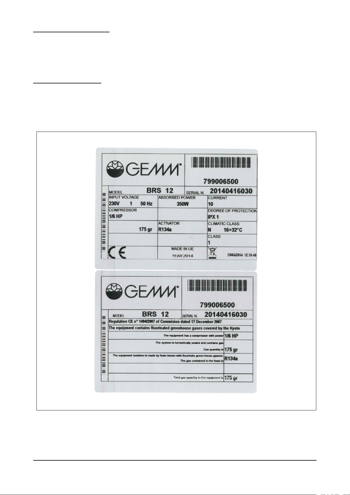
Fig. 1
La ringraziamo per aver scelto una nostra base refrigerata GN serie "BASIC”, conservatore TN / BT per la gastronomia.
Leggere con molta attenzione il presente manuale, mettendolo a disposizione del personale che dovrà installare, utilizzare
ed eseguire la manutenzione dell’apparecchiatura.
1.1 – DATI DI MARCATURA
In tutte le basi GN serie "BASIC”, le targhette di identificazione della macchina (nella fig.1 sotto rappresentate) si trovano
applicate sul fianco DX della scocca, vicino allo spigolo inferiore - anteriore (verso il pannello). Questa posizione vale in
tutti i casi, che la base sia ad 2 / 3 o 4 porte.
BRS Rev01-IT-EN NEUTRO 12-2014 pag. 6
Page 7
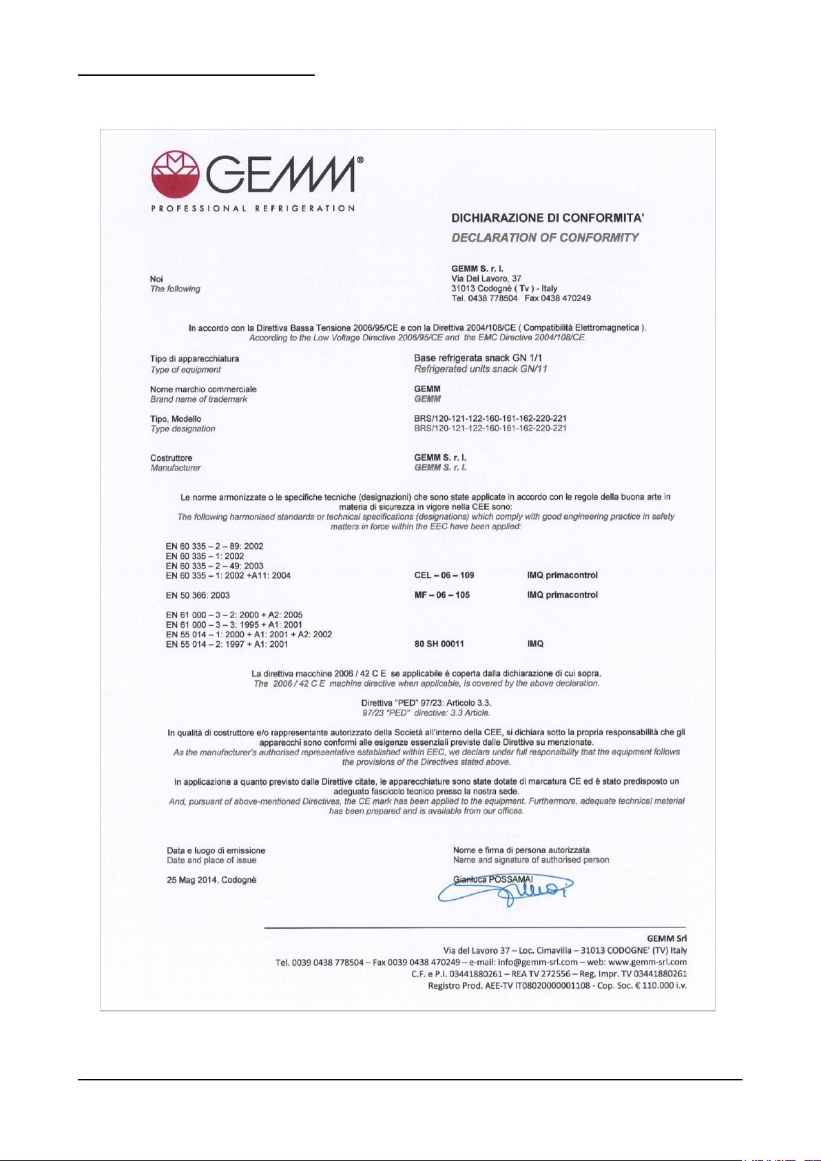
1.2 – DICHIARAZIONE DI CONFORMITA’
BRS Rev01-IT-EN NEUTRO 12-2014 pag. 7
Page 8

1.3 – GARANZIA
Questo simbolo contraddistingue informazioni ed avvertenze il cui mancato rispetto può danneggiare
l’apparecchiatura o compromettere la sicurezza del personale.
Questo simbolo contraddistingue informazioni ed avvertenze di carattere elettrico il cui mancato rispetto
può danneggiare l’apparecchiatura o compromettere la sicurezza del personale.
La garanzia sui componenti dell’apparecchiatura, avente decorrenza dalla data riportata sulla relativa bolla di consegna,
è come da contratto di vendita.
Non sono compresi nella garanzia danni all’apparecchiatura causati da:
- trasporto e/o movimentazione;
- errori dell’operatore;
- mancata manutenzione prevista nel presente manuale;
- guasti e/o rotture non imputabili al malfunzionamento dell’apparecchiatura;
- operazioni di manutenzione svolte da personale non qualificato;
- uso improprio.
1.4 – ASSISTENZA
Per qualsiasi necessità inerente l’uso, la manutenzione o la richiesta di parti di ricambio, l’acquirente è pregato di rivolgersi
direttamente al costruttore, specificando i dati identificativi dell’apparecchiatura riportati sulla targhetta di identificazione.
1.5 – UTILIZZO E CONSERVAZIONE DEL MANUALE
Il presente manuale ha lo scopo di fornire tutte le informazioni necessarie affinché, oltre ad un corretto utilizzo
dell’apparecchiatura, sia possibile gestire la stessa nel modo più autonomo e sicuro possibile.
Il manuale è suddiviso in capitoli, paragrafati e sotto paragrafati: la pagina dell’indice fornisce quindi un modo facile per
trovare qualunque aspetto di interesse.
Il materiale contenuto in questo documento viene fornito esclusivamente per scopi informativi ed è soggetto a modifiche
senza preavviso. Nonostante la massima attenzione riservata alla redazione del documento, la ditta costruttrice non è
responsabile per i danni derivanti da errori od omissioni e dall’utilizzo delle informazioni qui contenute.
Mantenere il presente manuale, e tutta la documentazione allegata, in buono stato, leggibile e completa di tutte le sue
parti; conservarla in prossimità dell’apparecchiatura, in un luogo accessibile e noto a tutti gli operatori.
1.5.1 – SIMBOLI UTILIZZATI NEL PRESENTE MANUALE
BRS Rev01-IT-EN NEUTRO 12-2014 pag. 8
Page 9

1.6 – DESCRIZIONE DEL PERSONALE
Gli operatori non devono eseguire operazioni riservate ai manutentori o ai tecnici specializzati.
Il costruttore non risponde di danni derivati dalla mancata osservanza di questo divieto.
Il manuale in oggetto è rivolto sia all’operatore che ai tecnici abilitati all’installazione ed alla manutenzione
dell’apparecchiatura.
- Operatore addetto all’uso dell’apparecchiatura: Personale specializzato in grado di operare con
l’apparecchiatura in condizioni normali attraverso l’uso dei comandi preposti. Deve inoltre essere in grado di
effettuare operazioni semplici di manutenzione ordinaria (pulizia, carico prodotto), avviamento o ripristino
dell’apparecchiatura in seguito ad un’eventuale sosta forzata.
- Tecnico specializzato elettricista: Tecnico specializzato elettricista che ha seguito i corsi di qualifica da parte
del produttore che gli consentono qualsiasi intervento sull’apparecchiatura. Il tecnico specializzato deve essere
in grado di installare l’apparecchiatura e di condurla in condizioni normali; è abilitato a tutti gli interventi di natura
elettrica e meccanica di regolazione, di manutenzione e di riparazione. E’ in grado di operare in presenza di
tensione all’interno di armadi elettrici e scatole di derivazione.
- Tecnico specializzato mulettista: Tecnico specializzato addetto alla movimentazione di materiale all’interno
dell’azienda e munito di patente per l’utilizzo di muletti.
BRS Rev01-IT-EN NEUTRO 12-2014 pag. 9
Page 10
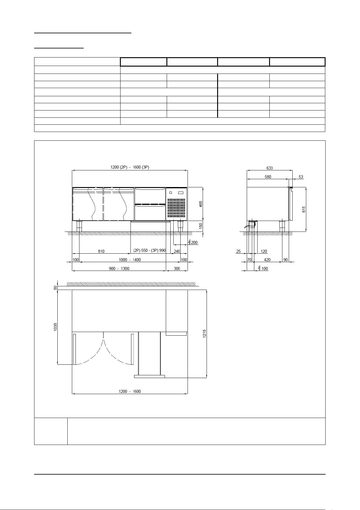
2 – DESCRIZIONE DELLA MACCHINA
Modello
BRS - 120
BRS - 160
BRSBT - 120
BRSBT - 160
Dimensioni esterne
cm
120 (2P) / 160 (3P) x 63 x 62h
Peso max
kg
n.d.
n.d.
n.d.
n.d.
Capacità litri
lt
170
265
170
265
Temperatura interna cella
°C
-2 / +8
-18 / -15
Gas e carica
gr
R 134 a 170
R 134 a 240
R 404 a 290
R 404 a 260
Potenza refrigerante
W
230
440
230
440
Potenza max assorbita
W
280
555
280
555
Tensione di alimentazione
Volt 1x230 ~ 50 Hz
Tab. 1/a
R
Alimentazione elettrica: cavo 3x1.5 mm2 completo di spina Schuko; L=4000 mm
Electricity supply: 3x1.5 mm2 wire complete with Schuko plug; L=4000 mm
Elektrischer Stromanschluss: Kabel 3x1,5 mm2 komplett mit Schukostecker; L=4000 mm
Alimentation électrique: câble 3x1.5 mm2 avec fiche Schuko; L=4000 mm
Fig. 2/a
2.1 – DATI TECNICI
BRS Rev01-IT-EN NEUTRO 12-2014 pag. 10
Page 11
Modello
BRS - 220
Dimensioni esterne
cm
220 x 63 x 62h
Peso max
kg
n.d.
Capacità litri
lt
170 + 170
Temperatura interna cella
°C
-2 / +8
Gas e carica
gr
R 134 a 280
Potenza refrigerante
W
460
Potenza max assorbita
W
555
Tensione di alimentazione
Volt 1x230 ~ 50 Hz
Tab. 1/b
R
Alimentazione elettrica: cavo 3x1.5 mm2 completo di spina Schuko; L=4000 mm
Electricity supply: 3x1.5 mm2 wire complete with Schuko plug; L=4000 mm
Elektrischer Stromanschluss: Kabel 3x1,5 mm2 komplett mit Schukostecker; L=4000 mm
Alimentation électrique: câble 3x1.5 mm2 avec fiche Schuko; L=4000 mm
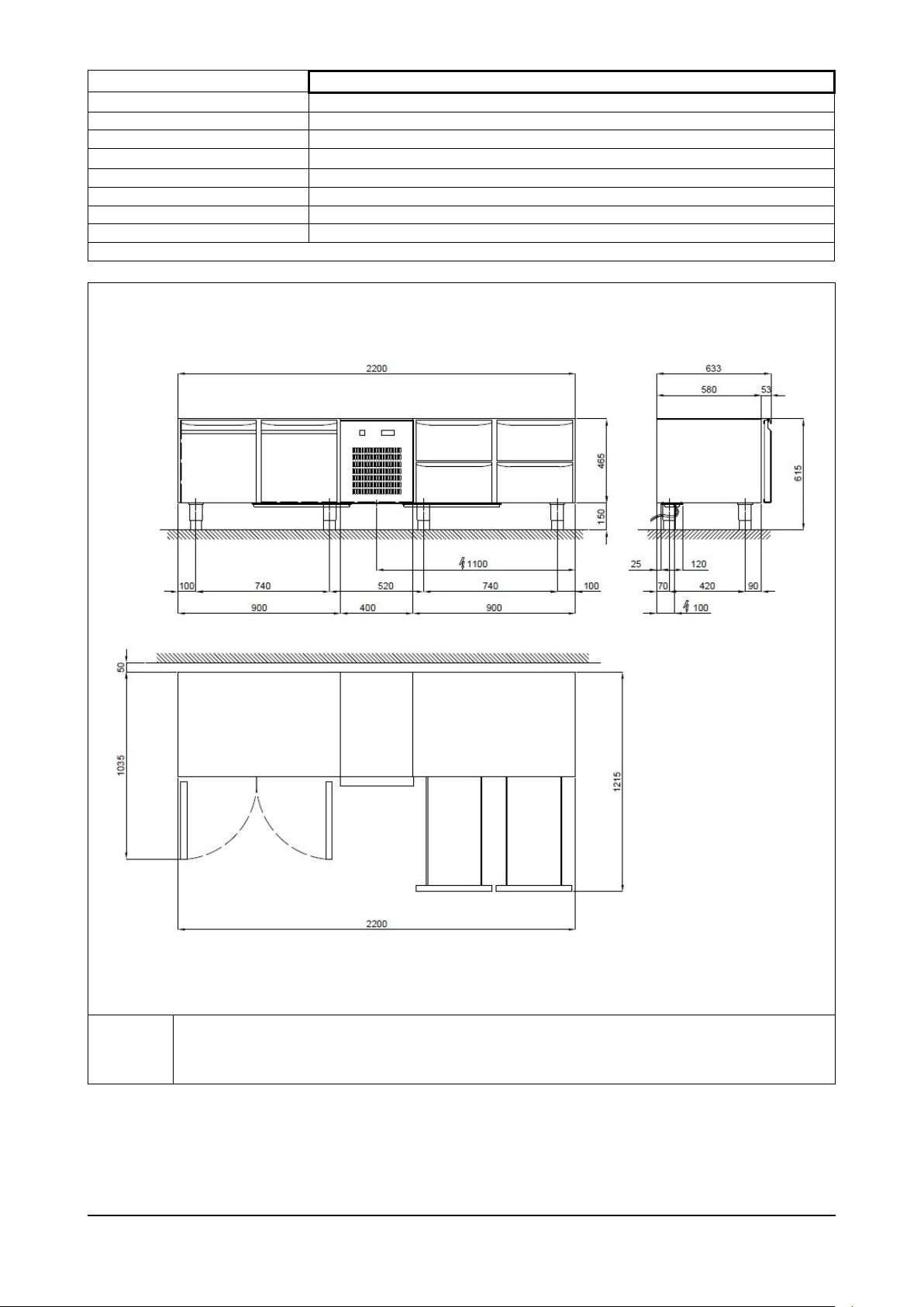
Fig. 2/b
BRS Rev01-IT-EN NEUTRO 12-2014 pag. 11
Page 12
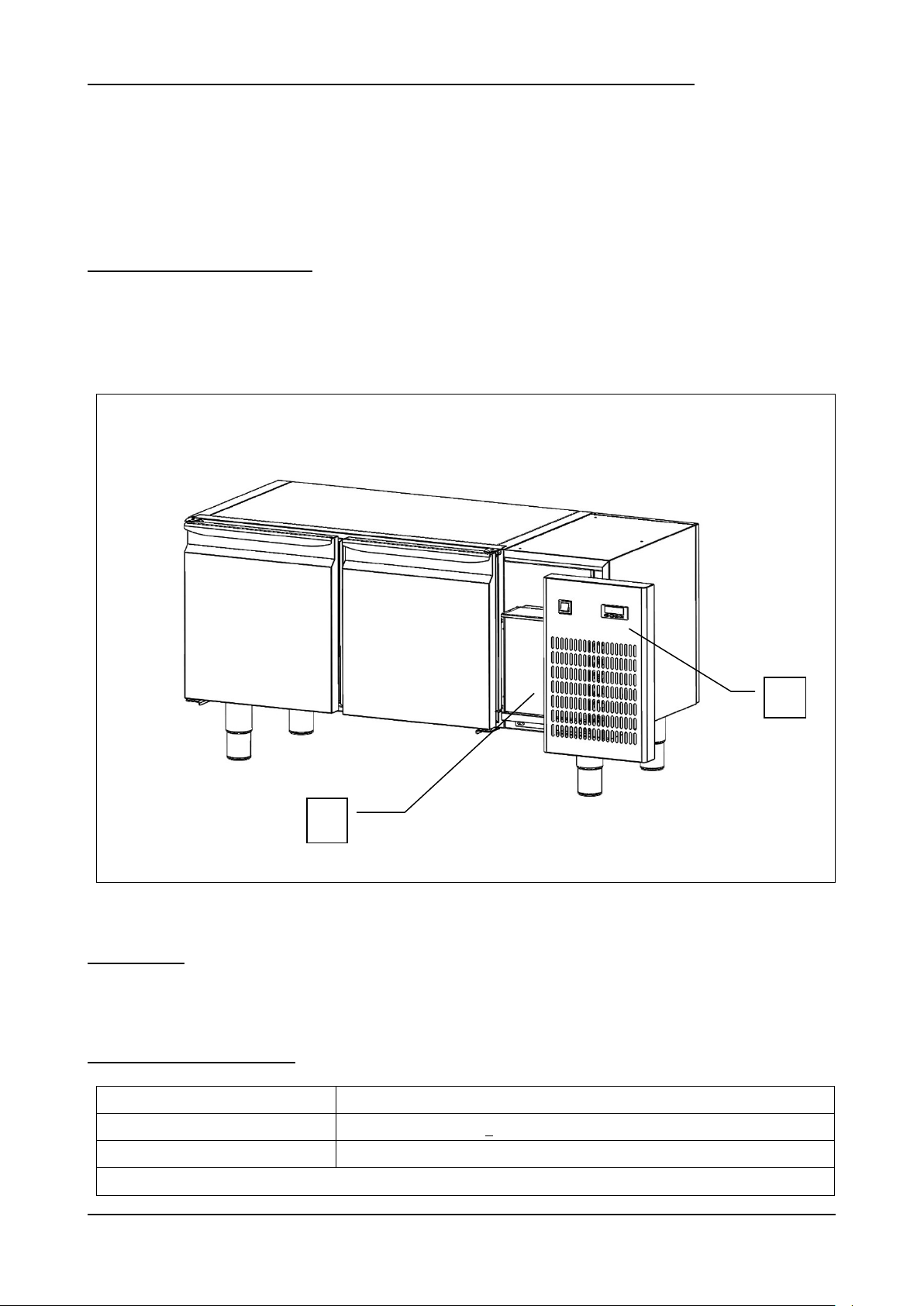
2.2 – DESCRIZIONE DELLA BASE REFRIGERATA GN SERIE " BASIC ” ED USO PREVISTO
Fig. 3
Luogo di installazione
Cucine , laboratori , Ristoranti , sale drink , show-room , bar .
Umidità dell’aria relativa
< 80% con assenza di condensa
Classe climatica
“N” + 16 °C ÷ + 32 °C
Tab. 2
2
1
Le basi gastronomia della serie " BASIC ”, sono realizzate in base ai principi di essenzialità e affidabilità.
La struttura è monoscocca, realizzata sia internamente che esternamente in acciaio inox AISI 304, con isolamento da 45
mm ottenuto mediante iniezione di resine poliuretaniche ad alta densità, esenti HCFC.
Il fondo interno cella è arrotondato per una facile pulizia, i piedini e la struttura reggigriglie sono realizzati in acciaio inox,
la porta è dotata di guarnizione magnetica ad incastro di facile sostituzione, pulizia , e riscaldata nelle versioni BT.
La refrigerazione è ventilata, con controllo tramite teletermostato digitale, sbrinamento automatico elettrico ed
evaporazione automatica dell’acqua di condensa.
2.2.1 – COMPONENTI PRINCIPALI
L’apparecchiatura è composta dai seguenti componenti:
corpo apparecchiatura;
impianto frigorifero (rif. 1, fig. 3);
pannello di controllo (rif. 2, fig. 3)
2.3 – RUMORE
L’apparecchiatura è stata progettata e realizzata in modo da ridurre al massimo il livello di potenza acustica.
Nello specifico si dichiara un livello acustico inferiore ai 60 decibel .
2.4 – CONDIZIONI AMBIENTALI
BRS Rev01-IT-EN NEUTRO 12-2014 pag. 12
Page 13
3. – SICUREZZA
IMPORTANTE: prima dell’utilizzo dell’apparecchiatura leggere attentamente il presente manuale d’uso
e seguire scrupolosamente le istruzioni tecniche di funzionamento e le indicazioni qui contenute.
L’operatore deve conoscere la posizione e le funzioni di tutti i dispositivi di controllo e le caratteristiche
del tavolo refrigerato.
La base refrigerata è conforme alle vigenti norme di sicurezza. L’uso improprio può comunque provocare
danni a persone o cose.
All’atto dell’installazione tutto il personale operativo deve essere opportunamente istruito sui rischi di
incidente, i dispositivi di sicurezza per l’operatore, le norme generali di prevenzione degli incidenti
previste dalle direttive internazionali e dalla legge vigente nel paese di utilizzo dell’apparecchiatura.
L’avvio e l’uso dell’apparecchiatura devono essere affidati esclusivamente a personale addestrato. Il
comportamento del personale operativo deve in ogni caso rispettare scrupolosamente le norme sulle
prevenzione degli incidenti vigenti nel paese di utilizzo dell’apparecchiatura.
Non rimuovere o alterare le targhe apposte dal costruttore sull’apparecchiatura.
La base refrigerata non deve essere messo in funzione in caso di difetti al pannello di controllo o parti
danneggiate.
Non ostruire i condotti di aerazione superiori e/o interni dell’apparecchiatura; non riporre il prodotto a
ridosso delle griglie di ventilazione, dei condotti di aerazione, o direttamente sul fondo della cella.
Segnalare tempestivamente eventuali anomalie di funzionamento.
Usare solamente accessori raccomandati dal costruttore.
Non esporre l’apparecchiatura a pioggia o a getti d’acqua
Le operazioni di manutenzione ordinaria e straordinaria che prevedono l’apertura del quadro elettrico
oppure uno smontaggio anche parziale della base refrigerata, devono essere effettuate solo dopo aver
interrotto l’alimentazione dell’apparecchiatura.
3.1 – AVVERTENZE GENERALI
Il produttore è sollevato da qualunque responsabilità nei seguenti casi:
mancata effettuazione della manutenzione programmata;
modifiche e/o interventi non autorizzati:
utilizzo di ricambi non originali;
mancato o parziale rispetto di quanto riportato nel presente manuale;
uso improprio dell’apparecchiatura.
BRS Rev01-IT-EN NEUTRO 12-2014 pag. 13
Page 14
Qualunque manomissione o sostituzione non autorizzata di una o più parti o componenti dell’apparecchiatura,
Fig. 4
3 1 2
l’utilizzo di accessori e materiale di consumo diversi dagli originali, possono rappresentare un rischio di incidente
e sollevano il costruttore da qualunque responsabilità civile o penale.
In caso di dubbio relativamente al funzionamento dell’apparecchiatura, non usarla e contattare il costruttore.
3.2 – CONTROINDICAZIONI D’USO
Le basi refrigerate GN serie " BASIC ”, non devono essere utilizzate:
per utilizzi diversi da quelli riportati nel paragrafo 2.2 “Descrizione della base refrigerata ed uso previsto” ;
con sistemi di sicurezza non funzionanti ;
dopo un’installazione non eseguita correttamente ;
da personale non addestrato ;
con interventi di manutenzione non eseguiti o eseguiti in modo scorretto ;
con utilizzo di ricambi non originali ;
con cavo di alimentazione e/o presa elettrica danneggiati ;
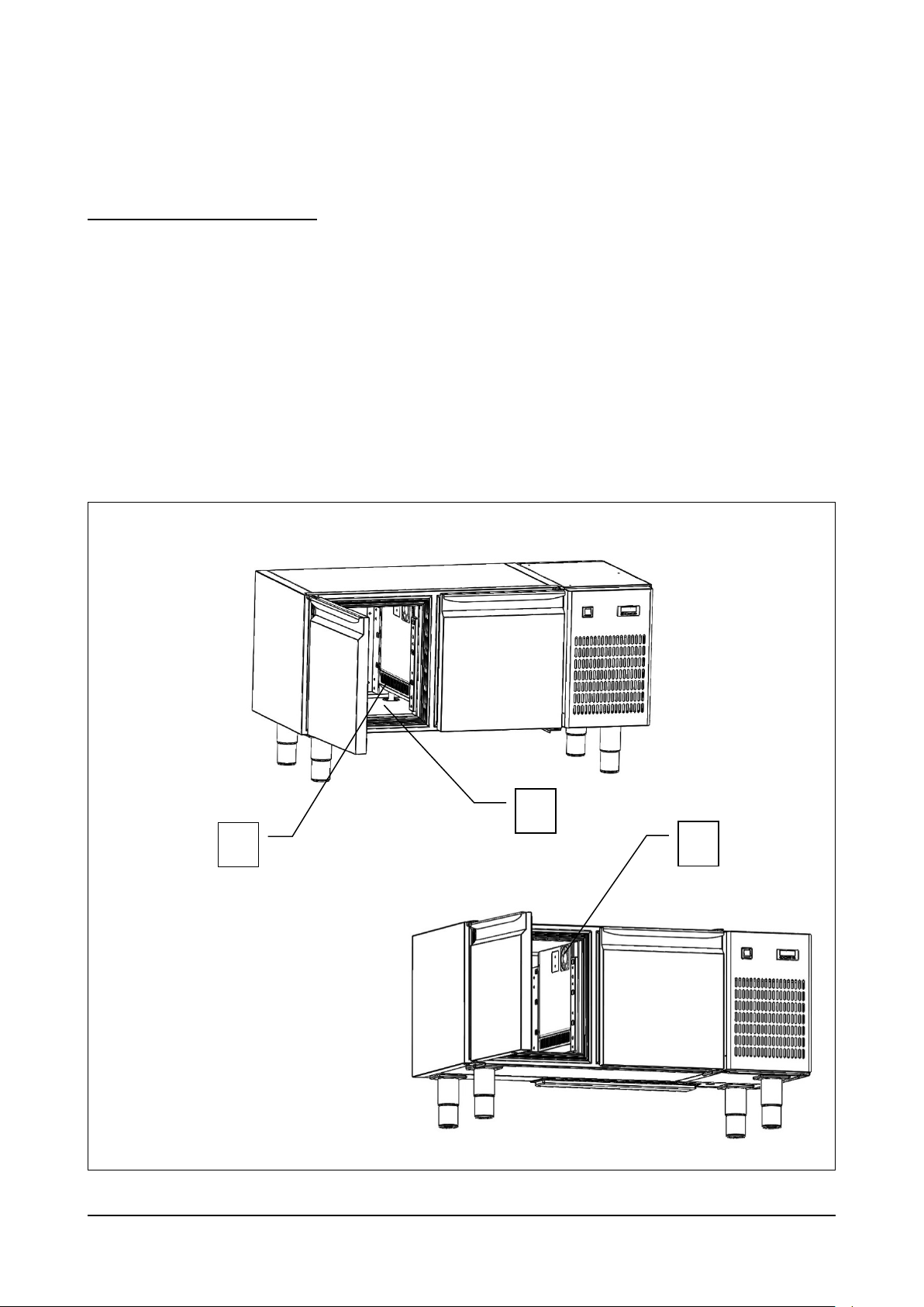
con condotti di aerazione (rif. 1, fig. 4) ostruiti ;
con prodotti alimentari vari (cibi e bevande) posti a ridosso delle griglie di ventilazione interne (rif. 3, fig. 4), o
direttamente sul fondo della cella (rif. 2, fig. 4).
BRS Rev01-IT-EN NEUTRO 12-2014 pag. 14
Page 15
3.3 – DISPOSITIVI DI PROTEZIONE
Fig. 5
2
1
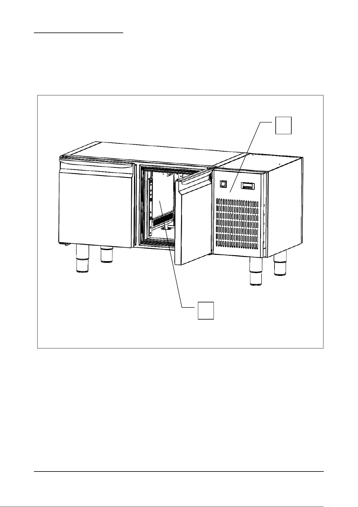
La protezione del personale esposto ai rischi, dovuti agli elementi mobili pericolosi, è garantita dalla presenza di opportuni
dispositivi presenti sull’apparecchiatura:
parete inox interna a copertura dell'evaporatore e delle ventole interne (rif. 1, fig. 5);
pannello frontale a copertura del ventilatore condensatore (rif. 2, fig. 5).
BRS Rev01-IT-EN NEUTRO 12-2014 pag. 15
Page 16
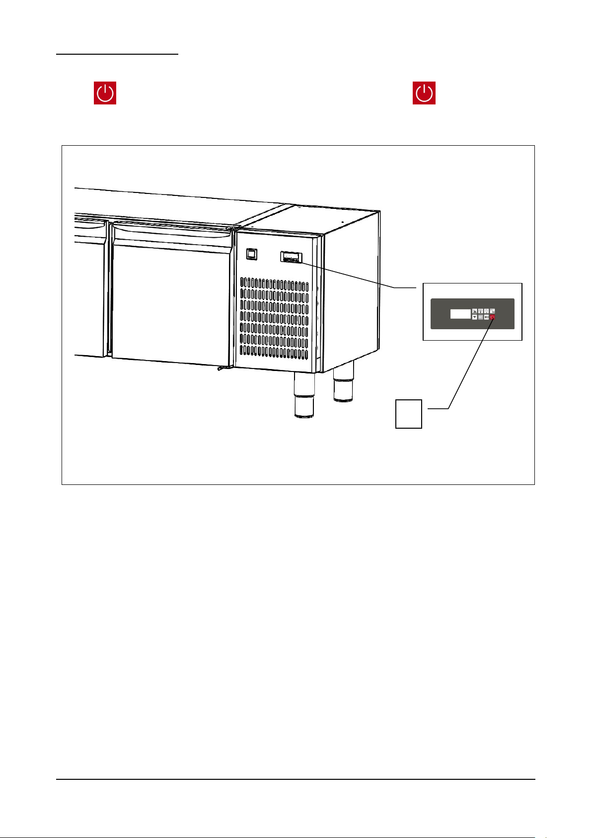
3.4 – FUNZIONI DI ARRESTO
Fig. 6
1
L' apparecchiatura nel suo complesso è controllata da un teletermostato digitale . La funzione di arresto è rappresentata
dal tasto (rif. 1 fig. 6). In qualsiasi stato si trovi la macchina , la pressione del tasto mette la scheda in OFF.
BRS Rev01-IT-EN NEUTRO 12-2014 pag. 16
Page 17
4 – TRASPORTO E MOVIMENTAZIONE
L’apparecchiatura non deve essere assolutamente capovolta.
L’imballo deve essere ben posizionato sul pianale del mezzo di trasporto e bloccato attraverso
l’utilizzo di funi appropriate.
E’ necessario prestare la massima attenzione durante tutte le fasi di sollevamento e
posizionamento della base, in modo da evitare danni, anche gravi, a persone o cose. Il
costruttore non si assume alcuna responsabilità per il mancato rispetto delle indicazioni
riportate per il sollevamento e il trasporto della base.
Durante la fase di trasporto la temperatura ambientale non deve mai scendere al di sotto dei 4°C.
Prestare attenzione durante le fasi di sollevamento e movimentazione della base; esiste il
pericolo di lesioni anche mortali contro il carico in movimento.
Tutte le operazioni di movimentazione e sollevamento devono essere effettuate con la massima
cautela, controllando che tutto il personale sia rigorosamente a distanza di sicurezza, e che
nessuno sosti sotto carichi sospesi, fermi o in movimento.
Prima di iniziare l’operazione, controllare tutta l’area di movimentazione dell’apparecchiatura,
in modo da rilevare l’eventuale presenza di punti pericolosi.
Durante la fase di trasporto la temperatura ambientale non dove mai scendere al di sotto del 4°C.
4.1 – TRASPORTO DELLA BASE REFRIGERATA
In funzione della tipologia e delle dimensioni e pesi sono stati utilizzati imballi adeguati a garantire l’integrità e la
conservazione durante il trasporto fino alla consegna all’acquirente.
La base refrigerata deve essere posizionata e mantenuta in piedi su bancale avvolto dal proprio cartone per tutta la durata
del trasporto.
La base refrigerata viene fornita al trasportatore pronto per lo spostamento.
Il materiale d’imballo, una volta disimballato la base refrigerata, dovrà essere eliminato e/o riutilizzato secondo le norme
vigenti del Paese di destinazione dell’apparecchiatura.
4.2. – MOVIMENTAZIONE DELLA BASE REFRIGERATA IMBALLATA
BRS Rev01-IT-EN NEUTRO 12-2014 pag. 17
Page 18
PERSONALE AUTORIZZATO
Modello
BRS / BRSBT
120
BRS / BRSBT
160
BRS - 220
Dimensioni
cm
120 x 63 x 62h
160 x 63 x 62h
220 x 63 x 62h
Peso
Kg
n.d. / n.d.
n.d. / n.d.
n.d.
Tab.3/a
L’impiego di attrezzature non adeguate può comportare incidenti al personale impiegato
nell’operazione e/o danni all’apparecchiatura.
Il costruttore non si assume alcuna responsabilità per l’uso improprio e non conforme di
apparecchi per il sollevamento, il trasporto e la movimentazione.
Tecnico specializzato mulettista.
Mezzi di protezione individuali:
- scarpe antinfortunistiche;
- guanti antinfortunistici.
Il personale addetto a tali operazioni non deve utilizzare anelli, orologi da polso, gioielli, capi di vestiario slacciati o sciolti,
quali ad esempio cravatte, indumenti strappati, sciarpe, giacche sbottonate o bluse con chiusure a lampo aperte ecc… In
generale il personale deve usare capi ad uso antinfortunistico.
4.2.1 – PESO E INGOMBRO DELLA BASE REFRIGERATA
4.2.2 – MEZZI NECESSARI
- Per il sollevamento dell’apparecchiatura deve essere utilizzato un muletto con portata minima adeguata.
BRS Rev01-IT-EN NEUTRO 12-2014 pag. 18
Page 19
5 – INSTALLAZIONE
Prestare la massima cautela nel maneggiare l’apparecchiatura, in modo da evitare danni alle cose o alle
persone.
L’apparecchiatura non deve essere messa in funzione in caso di difetti al pannello di controllo o parti
danneggiate.
Verificare che l’imballo non sia stato danneggiato durante il trasporto.
L’impiego di attrezzature non adeguate può comportare incidenti al personale impiegato
nell’operazione e/o danni all’apparecchiatura.
Il costruttore non si assume alcuna responsabilità per l’uso improprio e non conforme di
apparecchi per il sollevamento, il trasporto e la movimentazione.
PERSONALE AUTORIZZATO
Tecnico specializzato elettricista.
Mezzi di protezione individuali:
scarpe antinfortunistiche;
guanti antinfortunistici.
Il personale addetto a tali operazioni non deve utilizzare anelli, orologi da polso, gioielli, capi di vestiario slacciati o sciolti,
quali ad esempio cravatte, indumenti strappati, sciarpe, giacche sbottonate o bluse con chiusure a lampo aperte ecc… In
generale il personale deve usare capi ad uso antinfortunistico.
5.1 – PREDISPOSIZIONE ALL’INSTALLAZIONE
Per l’installazione occorre predisporre un’area di manovra adeguata alle dimensioni dell’apparecchiatura (vedi fig. 2) e dei
mezzi di sollevamento prescelti.
Il luogo di installazione dovrà essere predisposto di tutta l’impiantistica di collegamento necessaria alla messa in funzione
dell’apparecchiatura.
Il luogo scelto per l’installazione deve avere requisiti idonei a permettere l’utilizzazione dell’apparecchiatura in condizioni
di sicurezza. La zona deve essere tale da garantire una buona base di appoggio, con pavimentazione solida, livellata e
con finitura tale da garantire un’adeguata e sicura operatività del personale.
Il luogo d’installazione deve presentare un’illuminazione, naturale e/o artificiale, adeguata alle operazioni da svolgere (in
base alle norme specifiche).
5.2 – DISIMBALLAGGIO
5.2.1 – MEZZI NECESSARI
Per il sollevamento dell’apparecchiatura deve essere utilizzato un muletto o un’attrezzatura equivalente.
BRS Rev01-IT-EN NEUTRO 12-2014 pag. 19
Page 20
5.2.2 – PROCEDURA DI DISIMBALLAGGIO
Tutte le operazioni di movimentazione e disimballaggio devono essere effettuate con la massima
cautela, controllando che tutto il personale sia rigorosamente a distanza di sicurezza, e che
nessuno sosti sotto carichi sospesi, fermi o in movimento.
DOPO LA FASE DI INSTALLAZIONE DELL’APPARECCHIATURA, ATTENDERE ALMENO DUE
ORE PRIMA DI PROCEDERE ALL’ACCENSIONE DI ESSA.
L’impiego di attrezzature non adeguate può comportare incidenti al personale impiegato
nell’operazione e/o danni all’apparecchiatura.
Il costruttore non si assume alcuna responsabilità per l’uso improprio e non conforme di
apparecchi per il sollevamento, il trasporto e la movimentazione.
Tutte le operazioni di movimentazione e disimballaggio devono essere effettuate con la massima
cautela, controllando che tutto il personale sia rigorosamente a distanza di sicurezza, e che
nessuno sosti sotto carichi sospesi, fermi o in movimento.
Per disimballare l’apparecchiatura è sufficiente togliere il cartone posto attorno ad essa. Procedere, successivamente, a
far scendere l’apparecchiatura dal bancale, sollevandola attraverso l’utilizzo di un apposito muletto; le forche del muletto
vanno poste sotto all’apparecchiatura.
5.3 – MOVIMENTAZIONE DELLA BASE REFRIGERATA
5.3.1 – MEZZI NECESSARI
Vedi paragrafo 5.2.1.
5.3.2 – PROCEDURA DI MOVIMENTAZIONE DELLA BASE DISIMBALLATA
Per movimentare la base, procedere al sollevamento attraverso l’utilizzo di un apposito muletto; le forche del muletto vanno
poste sotto all’apparecchiatura.
5.4 – MONTAGGIO DELLA BASE REFRIGERATA
Il cliente riceve la base refrigerata, montata in tutte le sue parti.
BRS Rev01-IT-EN NEUTRO 12-2014 pag. 20
Page 21
6 – MESSA IN OPERA
DOPO LA FASE DI INSTALLAZIONE DELL’APPARECCHIATURA, ATTENDERE ALMENO DUE
ORE PRIMA DI PROCEDERE ALL’ACCENSIONE DELLA STESSA.
Il collegamento elettrico deve essere effettuato da un tecnico specializzato elettricista.
Controllare che la tensione di alimentazione indicata sulla targhetta di identificazione
corrisponda a quella disponibile sulla rete elettrica del luogo di installazione.
L’impianto deve essere eseguito secondo le norme vigenti; le rete di alimentazione deve avere
un efficiente impianto di terra secondo le normative elettriche esistenti nel paese; questa
responsabilità è a carico del cliente.
Non provocare piegature strette sul cavo di alimentazione e non appoggiarvi sopra oggetti di
qualsiasi natura.
Nel caso in cui fosse necessario staccare la spina di alimentazione, assicurarsi prima che il tasto
, sia posizionato su OFF .
Il costruttore declina ogni responsabilità per danni o incidenti causati dall’inosservanza di dette
norme.
Interventi di regolazione eseguiti da personale non autorizzato possono danneggiare
l’apparecchiatura ed esporre l’operatore a seri pericoli. Interventi di regolazione eseguiti da
personale non autorizzato sono considerati manomissioni dell’apparecchiatura e come tali ne
fanno decadere la garanzia e sollevano il costruttore da qualunque responsabilità.
6.1 – COLLEGAMENTI
6.1.1 – COLLEGAMENTO ELETTRICO
PROCEDURA DI COLLEGAMENTO ELETTRICO
L’apparecchiatura viene fornita dal costruttore completa di spina di alimentazione. E’ sufficiente collegare la spina di
alimentazione ad una presa di corrente dell’impianto del luogo di installazione; l’impianto deve essere eseguito secondo
le norme vigenti.
L’energia elettrica del luogo d’installazione deve avere i seguenti requisiti:
Tensione: 230 Vac
Frequenza: 50 Hz
6.2 – CONTROLLI PRELIMINARI
L’installatore elettricista dovrà istruire l’operatore sull’utilizzo corretto della base refrigerata e trasmettere le nozioni basilari
di manutenzione.
MODALITA’
Le operazioni di preparazione della base refrigerata per il primo avviamento, devono essere eseguite da un tecnico
specializzato, in presenza dell’operatore addetto all’uso dell’apparecchiatura che avrà così la possibilità di acquisire un
minimo di informazioni atte a svolgere successivamente l’attività di manutenzione ordinaria consentita e di pulizia.
Prima della messa in funzione dell’apparecchiatura, è necessario eseguire una serie di verifiche e controlli allo scopo di
prevenire errori od incidenti durante la fase di messa in funzione.
Verificare che l’apparecchiatura non abbia subito danni durante la fase di trasporto.
Verificare , con particolare cura, l’integrità del quadro elettrico, pulsantiera di comando, cavi elettrici e tubazioni.
Controllare l’esatto collegamento di tutte le fonti di energia esterne.
Controllare il corretto livellamento della macchina.
6.2.1 – REGOLAZIONI
BRS Rev01-IT-EN NEUTRO 12-2014 pag. 21
Page 22
7 – USO
DOPO LA FASE DI INSTALLAZIONE DELL’APPARECCHIATURA, ATTENDERE ALMENO DUE
ORE PRIMA DI PROCEDERE ALL’ACCENSIONE DELLA STESSA.
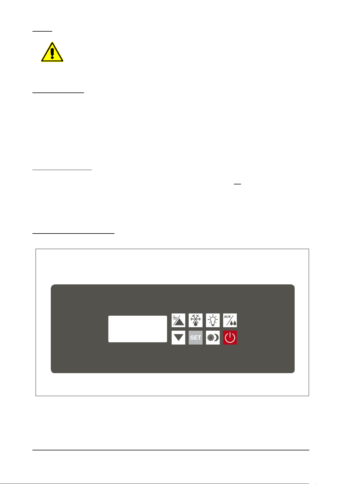
Fig. 7
7.1 – USO PREVISTO
La serie “BASIC” è sinonima di basi refrigerate e conservatori per la gastronomia professionale estremamente semplici ed
affidabili. Costruiti completamente in acciaio inox 304 secondo adeguati standard qualitativi, sono dotati di isolamento da
45mm ottenuto con iniezione di resine poliuretaniche esenti HCFC. Sono controllati da un teletermostato digitale di facile
lettura e programmazione. La refrigerazione è ventilata, lo sbrinamento è automatico con dispositivo per l’eliminazione
automatica dell’acqua di condensa.
7.2 – USI NON PREVISTI
Non sono previsti per la base refrigerata GN utilizzi diversi da quelli descritti al punto 7.1. In particolare la base non è
un’apparecchiatura adatta al raffreddamento rapido di prodotti alimentari vari, cibi e/o bevande.
7.3 – PANNELLO DI CONTROLLO
BRS Rev01-IT-EN NEUTRO 12-2014 pag. 22
Page 23
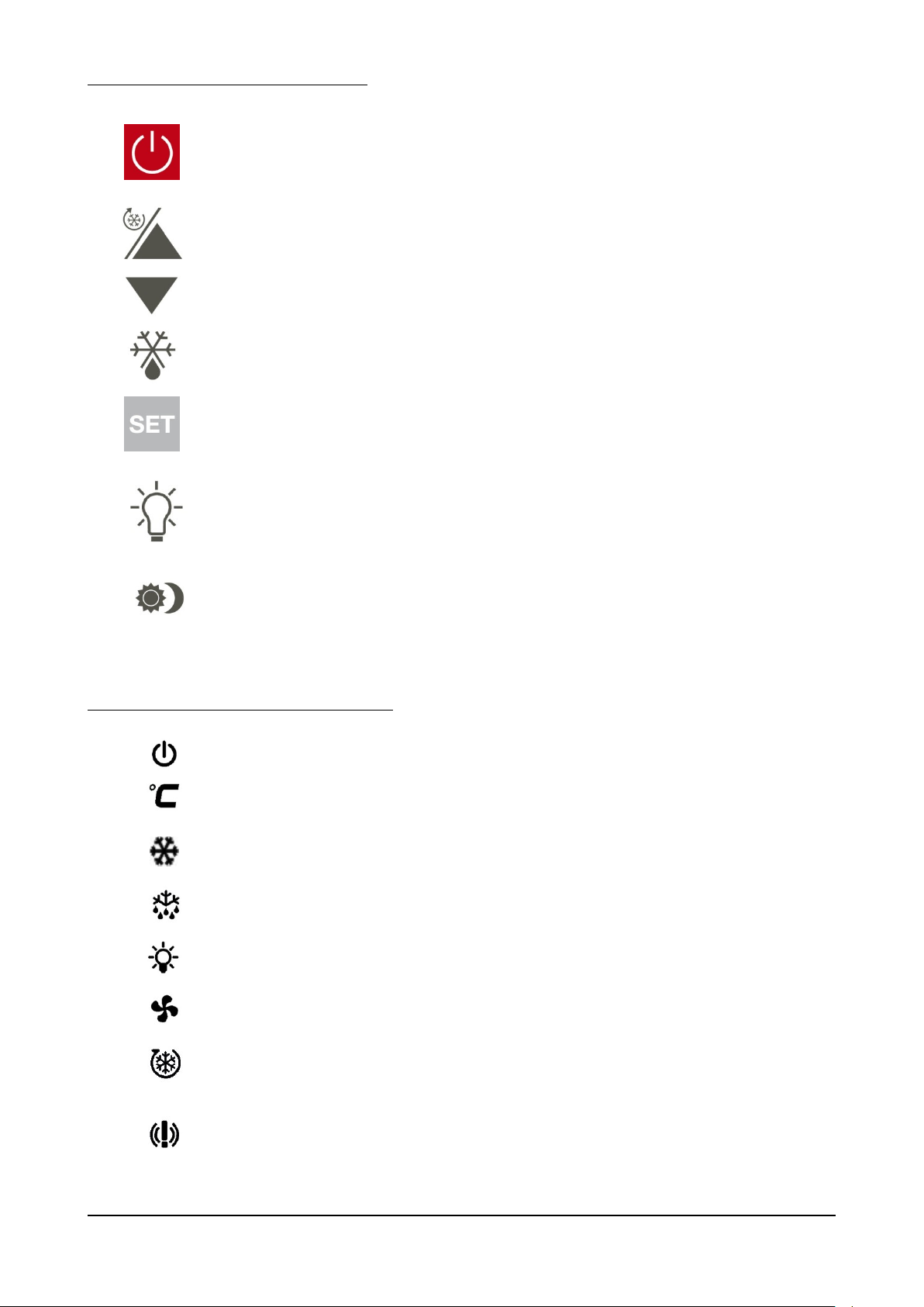
I tasti presenti sul controllore sono i seguenti:
TASTO 0/1, ON-OFF
Con macchina in OFF (0) la singola pressione permette di
passare allo stato di ACCESA (1).
Mentre la vetrina è accesa , dopo aver attivato la tastiera
premendo per 3sec qualsiasi tasto, la singola pressione mette la
scheda in OFF.
TASTI PIU’ E MENO
Permettono di incrementare o diminuire il valore che appare sul
display. A tastiera attiva, la pressione continua per 3sec del tasto
freccia SU permette di attivare il ciclo continuo a tempo.
TASTO DEFROST
Con la macchina ACCESA la pressione continua per 3sec
permette di effettuare lo sbrinamento.
TASTO SET
Con la macchina ACCESA, a tastiera attiva, la singola pressione
permette di visualizzare il set point, la pressione continua per 3
sec permette di modificare il set point.
TASTO LUCE
Con la macchina ACCESA, a tastiera attiva, la singola
pressione permette di accendere o spegnere la luce interno
cella .
TASTO ENERGY SAVING
Con la macchina ACCESA, a tastiera attiva, la pressione
continua per 3sec. permette di attivare o disattivare la funzione
"notturna" di energy saving .
OFF
E’ accesa quando la macchina si trova nello stato di OFF ed è
spenta in tutti gli altri casi.
CELSIUS
Può essere accesa ed indicare l’unità di misura della temperatura.
COMPRESSORE
E’ accesa durante le fasi normali di refrigerazione, compressore ON,
spenta con compressore OFF. E’ lampeggiante durante la fase di
sgocciolamento del defrost.
DEFROST
E’ accesa durante una fase di DEFROST.
LUCE
E’ accesa solo quando sono accese le luci interno cella.
VENTOLE
E’ accesa solo quando sono in funzione le ventole interno cella
(Evaporatore).
CICLO CONTINUO
E’ accesa solo quando viene attivato il ciclo continuo (ciclo a
tempo).
ALLARMI
E’ accesa solo quando viene registrato, dalla centralina, un allarme
e/o un malfunzionamento dell’apparecchiatura.
Le icone presenti sul display del controllore sono:
BRS Rev01-IT-EN NEUTRO 12-2014 pag. 23
Page 24

7.4 – PROCEDURE PER IL CONTROLLO
L' apparecchiatura nel suo complesso è controllata da un teletermostato digitale da retropannello.
Nel momento in cui la macchina viene alimentata elettricamente il display dell’apparecchiatura si illumina completamente
per un “lamp-test” di alcuni secondi al termine del quale si riporta nello stato in cui si trovava prima che l’alimentazione
fosse tolta. In particolare se era in corso un ciclo questo riprenderà dove è stato interrotto.
Con scheda in OFF il display è completamente spento ad eccezione dell’icona . Con la pressione del tasto il
display spegne l’icona e si porta in ACCESA visualizzando la temperatura presente in cella.
Utilizzando i comandi posti sul teletermostato ed aiutandosi con le indicazioni del display è possibile attivare le diverse
funzioni della macchina.
E’ possibile tacitare la segnalazione acustica, di qualsiasi origine essa sia, premendo un tasto qualsiasi.
In qualsiasi stato si trovi la macchina, la pressione del tasto mette la scheda in OFF.
7.5 – PROCEDURE PER L’UTILIZZO
Prima di utilizzare la macchina è opportuno eseguire un’accurata pulizia all’interno della cella.
E’ buona norma dopo l’installazione o dopo un lungo periodo di inutilizzo far lavorare l’apparecchiatura a vuoto fino al
raggiungimento della temperatura impostata.
Per ottenere una buona resa dell’armadio refrigerato si consiglia di sistemare il prodotto in modo da favorire la circolazione
dell’aria: non ostruire l’aspirazione del gruppo frigorifero, non sovrapporre cibi e bevande, distribuire in maniera ordinata il
carico.
Per non avere forti rallentamenti nella resa del gruppo frigo, si consiglia di non sovraccaricare la macchina oltre le quantità
consentite, di non introdurre prodotti quali cibi e/o bevande con una temperatura superiore a quella dell’ambiente indicato
di progetto e di evitare inutili aperture porta.
BRS Rev01-IT-EN NEUTRO 12-2014 pag. 24
Page 25
7.6 – UTILIZZI
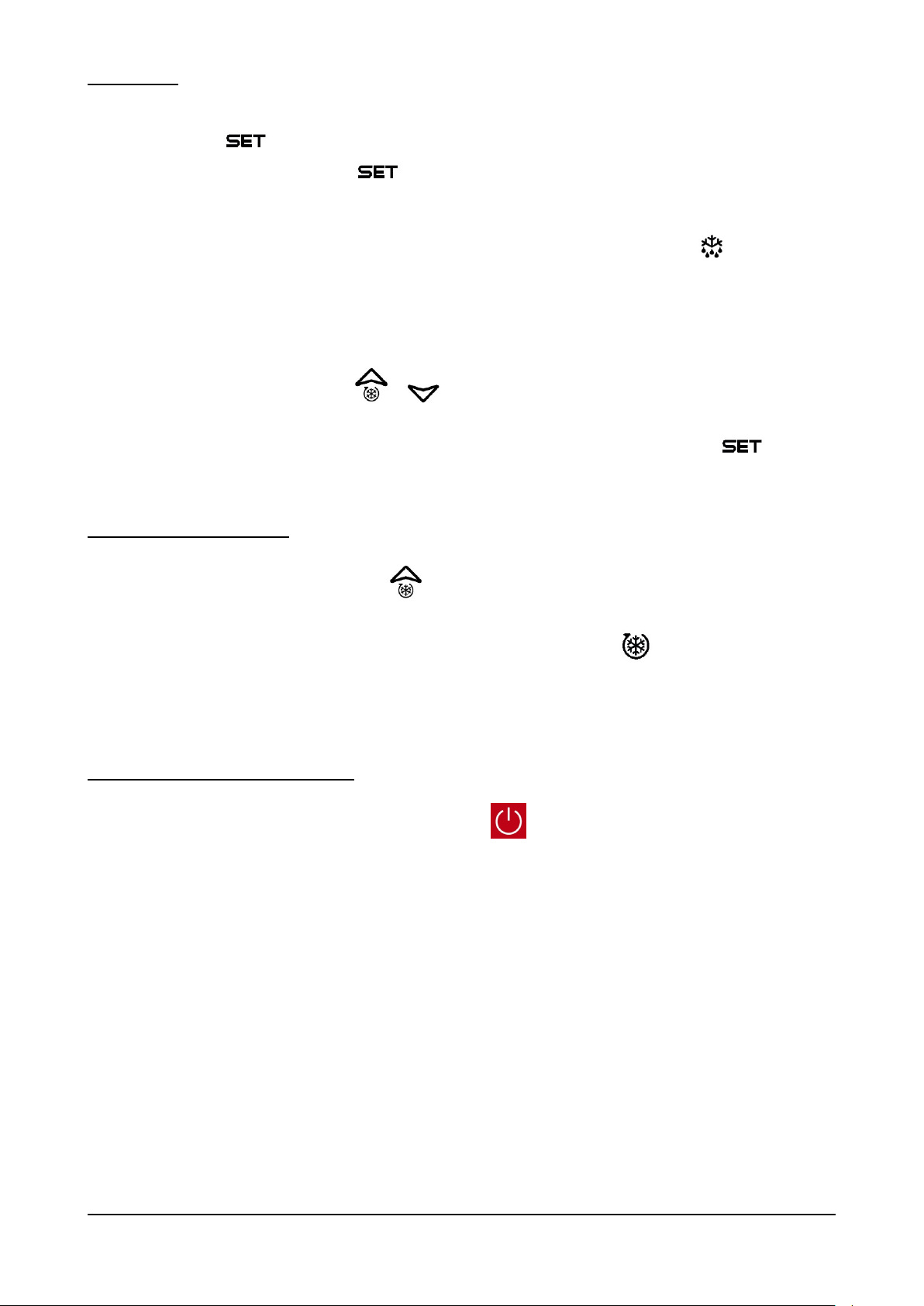
- Con il tasto , è possibile visualizzare il set-point e modificarlo se necessario.
con la pressione singola del tasto viene solo visualizzata la temperatura impostata, con la pressione per
3sec dello stesso tasto questo valore, con le frecce su e giù, è anche modificabile.
- E’ possibile selezionare una fase di defrost manuale; con la pressione per 3sec del tasto se la temperatura
dell’evaporatore non è superiore ai +8°C, viene attivata una fase di defrost manuale. Questa fase termina o a
tempo trascorsi 20’ o a temperatura rilevata dalla sonda all’evaporatore (+8/+5°C TN/BT). Il defrost automatico,
gestito dal teletermostato, avviene ogni 8H sempre con una durata max di 20’ ed è segnalato a display dalla
scritta dEF .
- Con la pressione singola dei tasti e è possibile visualizzare rispettivamente la temperatura massima
e la temperatura minima registrate dalla sonda interno cella. I valori visualizzati vengono preceduti rispettivamente
dalle scritte LO e HY . Nel momento della visualizzazione, con la pressione per 3sec del tasto è possibile
resettare questo valore memorizzato. Questa operazione è preceduta dalla scritta RST (reset) .
7.6.1 – UTILIZZI PARTICOLARI
- Con la pressione per 3sec del tasto è possibile attivare la fase CICLO CONTINUO . Questa fase è
contraddistinta da una durata (1H) e una temperatura (-2/-21°C TN/BT) valori impostati dal costruttore nella
centralina. Inoltre per differenziarsi da una normale fase frigorifera, il simbolo a display è acceso. Una volta
trascorso il tempo (1H) impostato, il simbolo si spegnerà e l’apparecchiatura riprenderà a funzionare con il
precedente set point impostato.
7.6.2 – ARRESTO PER LUNGHI PERIODI
Mettere la macchina in OFF , a tastiera attiva, premendo il tasto e scollegare la spina.
Procedere ad una approfondita pulizia della macchina (come da paragrafo 8.2) e assicurarsi di lasciare la porta aperta al
termine dell’operazione e per tutto il periodo di inattività.
BRS Rev01-IT-EN NEUTRO 12-2014 pag. 25
Page 26
8 – MANUTENZIONE
Il costruttore deve essere contattato per qualunque anomalia non descritta nel presente manuale; il
costruttore deve essere contattato anche per qualsiasi dubbio riscontrato durante le operazioni di
manutenzione qui descritte. Interventi di manutenzione eseguiti da personale non autorizzato
possono danneggiare l’apparecchiatura ed esporre l’operatore a seri pericoli. Interventi di
manutenzione eseguiti da personale non autorizzato sono considerati manomissioni all’apparecchio
e come tali ne fanno decadere la garanzia e sollevano il costruttore da qualunque responsabilità.
Qualsiasi operazione di manutenzione ordinaria o straordinaria che preveda l’apertura del
quadro elettrico oppure uno smontaggio anche parziale della macchina deve essere
effettuata solo dopo che l’apparecchiatura è stata spenta e che la spina è stata scollegata.
Qualsiasi operazione di manutenzione effettuata sulla macchina con l’impianto elettrico sotto
tensione può provocare gravi incidenti, anche mortali, alle persone.
La disattivazione dei dispositivi di protezione deve essere effettuata solo da personale autorizzato,
il quale provvederà a garantire l’incolumità di persone e ad evitare qualsiasi danno alla macchina.
Dopo aver eseguito la manutenzione necessaria, i dispositivi di protezione devono essere riattivati
correttamente.
Durante le operazioni di manutenzione o riparazione, persone non autorizzate devono tenersi a
distanza dell’apparecchiatura.
Rispettate gli intervalli prescritti o indicati nel presente manuale per l’esecuzione di controlli.
Al termine delle operazioni di manutenzione o riparazione è possibile riavviare l’apparecchiatura solo
dopo che il tecnico specializzato si sia accertato che:
- i lavori siano stati effettuati completamente;
- i sistemi di sicurezza siano attivi;
- l’apparecchiatura funzioni perfettamente;
- nessuno stia operando sull’apparecchiatura.
Componente
Tipo di intervento
Tempificazione
Responsabilità
Modalità
Cella interna
Pulizia
Secondo necessità
Operatore addetto all’uso dell’apparecchiatura
Vedi par. 8.2.2
Parte esterna
Pulizia
Secondo necessità
Operatore addetto all’uso dell’apparecchiatura
Vedi par. 8.2.3
Condensatore
Pulizia
Ogni 60 giorni
Operatore addetto all’uso dell’apparecchiatura
Vedi par. 8.2.4
Tab. 4
8.1 – PRECAUZIONI PARTICOLARI
8.2 – MANUTENZIONE ORDINARIA
8.2.1 – TABELLA RIASSUNTIVA DELLE MANUTENZIONI ORIDNARIE (TAB. 4)
8.2.2 – PULIZIA CELLA INTERNA
Questa operazione deve essere effettuata secondo necessità.
STATO DELL’APPARECCHIATURA:
- pulsante di accensione/spegnimento in posizione OFF ;
- spina di alimentazione scollegata dalle rete elettrica.
BRS Rev01-IT-EN NEUTRO 12-2014 pag. 26
Page 27
PERSONALE AUTORIZZATO
Per la pulizia dell’apparecchiatura utilizzare solo ed esclusivamente acqua e detergente neutro non
abrasivo. L’utilizzo di prodotti diversi può causare il danneggiamento delle superfici
dell’apparecchiatura e compromettere la qualità e la salubrità del prodotto trattato.
Non utilizzare spugne abrasive.
Non effettuare la pulizia attraverso l’utilizzo di panni che potrebbero rilasciare fibre e non utilizzare
getti d’acqua diretti nell’apparecchiatura.
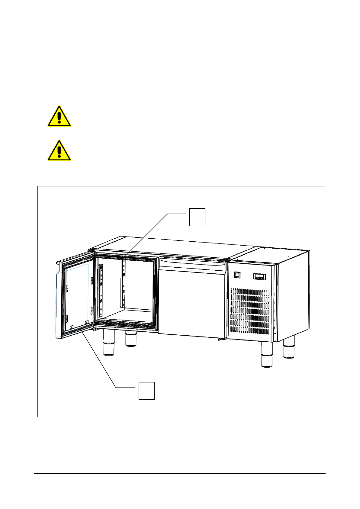
Fig. 8
1
2
Operatore addetto all’uso dell’apparecchiatura.
MODALITA’
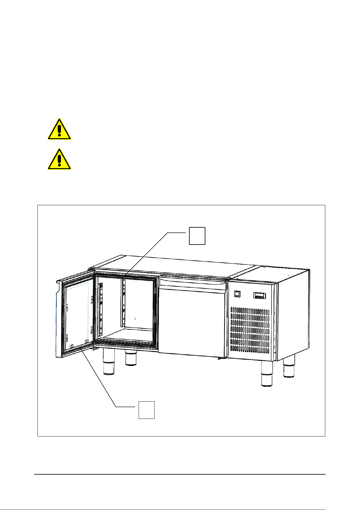
Pulire con estrema cura la parte interna della cella, la superficie di chiusura della porta (rif. 1 fig. 8) e la guarnizione (rif. 2
fig. 8), utilizzando una spugna imbevuta di detergente neutro, entrambi non abrasivi. Terminata la pulizia sciacquare,
attraverso l’utilizzo di una spugna pulita imbevuta d’acqua, e asciugare attraverso l’utilizzo di un panno pulito.
Una corretta pulizia interna dell’apparecchiatura, evita la formazione di cattivi odori che potrebbero danneggiare il prodotto
finale.
BRS Rev01-IT-EN NEUTRO 12-2014 pag. 27
Page 28
8.2.3 – PULIZIA PARTE ESTERNA DELL’APPARECCHIATURA
Per la pulizia dell’apparecchiatura utilizzare solo ed esclusivamente acqua e detergente neutro non
abrasivo. L’utilizzo di prodotti diversi può causare il danneggiamento delle superfici
dell’apparecchiatura e compromettere la qualità e la salubrità del prodotto trattato.
Non utilizzare spugne abrasive.
Non effettuare la pulizia attraverso l’utilizzo di panni che potrebbero rilasciare fibre.
Questa operazione deve essere effettuata secondo necessità.
STATO DELL’APPARECCHIATURA:
- pulsante di accensione/spegnimento in posizione OFF ;
- spina di alimentazione scollegata dalle rete elettrica.
PERSONALE AUTORIZZATO
Operatore addetto all’uso dell’apparecchiatura.
MODALITA’
Pulire le superfici esterne dell’apparecchiatura (porta fianchi e pannellature in acciaio), utilizzando una spugna imbevuta
di detergente neutro, entrambi non abrasivi. Terminata la pulizia sciacquare, attraverso l’utilizzo di una spugna pulita
imbevuta d’acqua, e asciugare attraverso l’utilizzo di un panno pulito.
BRS Rev01-IT-EN NEUTRO 12-2014 pag. 28
Page 29
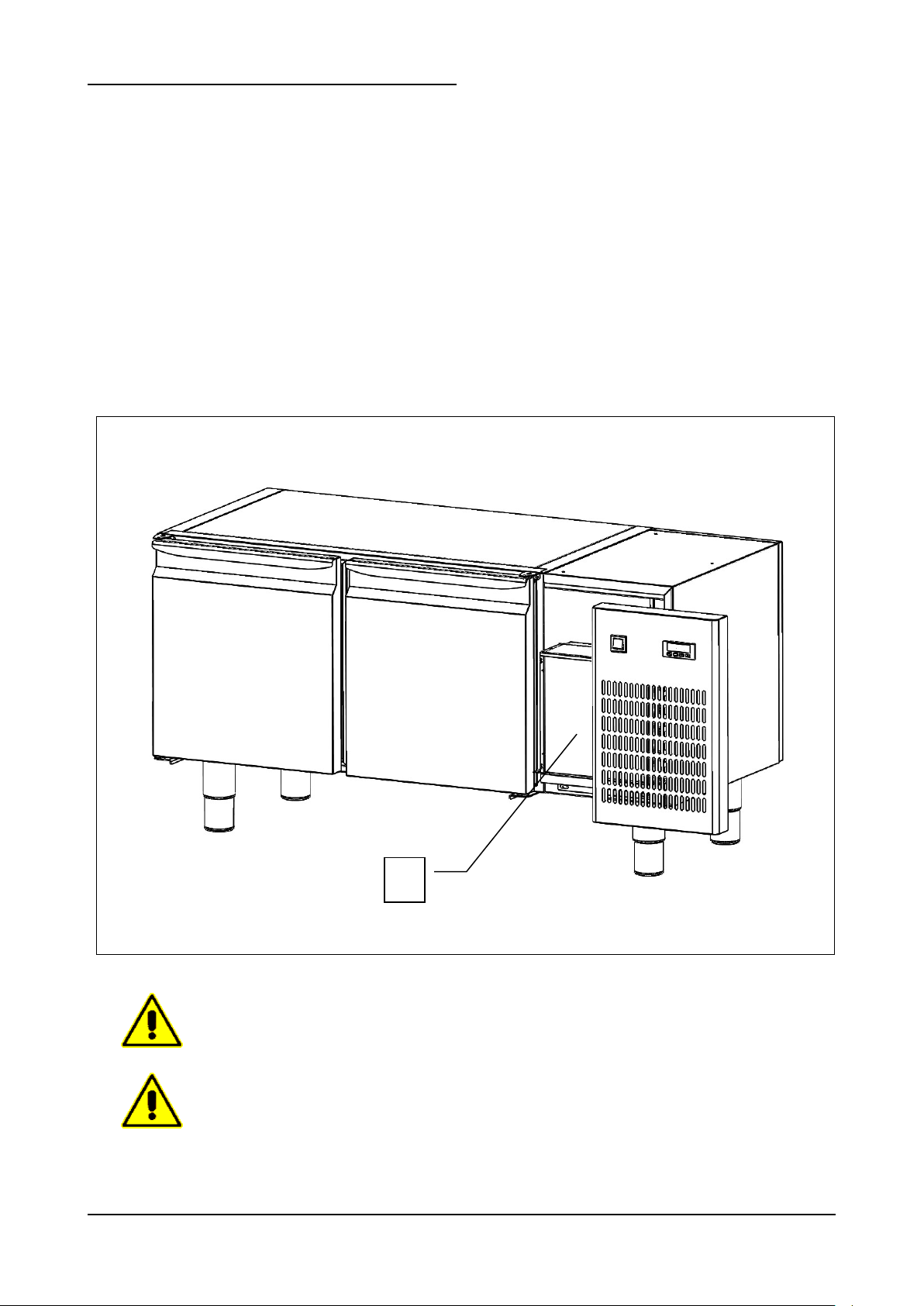
8.2.4 – PULIZIA CONDENSATORE APPARECCHIATURA
Fig. 9
Il condensatore presenta bordi taglienti. Durante le sopracitate operazioni indossare sempre
guanti protettivi, occhiali e maschere di protezione delle vie respiratorie.
Per la pulizia non utilizzare getti d’acqua diretti nell’apparecchiatura.
1
Questa operazione deve essere effettuata ogni 60 gg.
STATO DELL’APPARECCHIATURA:
- pulsante di accensione/spegnimento in posizione OFF ;
- spina di alimentazione scollegata dalle rete elettrica.
PERSONALE AUTORIZZATO
Operatore addetto all’uso dell’apparecchiatura.
MODALITA’
Per un corretto ed efficiente funzionamento dell'impianto frigorifero e quindi dell’apparecchiatura, è necessario che il
condensatore ad aria (rif. 1 fig. 9) sia mantenuto sempre pulito. Questa operazione è da farsi ogni 60 gg. massimo.
Effettuare la pulizia con spazzole non metalliche in modo da rimuovere tutta la polvere e la lanugine dalle alette. Si consiglia
l’uso di un aspirapolvere per evitare di disperdere nell’ambiante la polvere. Qualora ci siano dei depositi untuosi, eliminarli
usando un pennello imbevuto d’alcool. NON RASCHIARE LE SUPERFICI CON CORPI APPUNTITI O ABRASIVI.
BRS Rev01-IT-EN NEUTRO 12-2014 pag. 29
Page 30

8.3 – MANUTENZIONE STRAORDINARIA
Per qualsiasi attività di smontaggio dell’apparecchiatura contattare l’installatore.
Nel caso in cui l’apparecchiatura necessitasse di interventi di manutenzione straordinaria, o nel caso in cui riportasse delle
anomalie di funzionamento non trattate nel presente manuale, contattare il costruttore.
8.4 – ANOMALIE DI FUNZIONAMENTO E GUASTI
E’ importante ricordare che in qualsiasi stato si trovi la macchina, la pressione del tasto mette la scheda in OFF.
Ogni anomalia di funzionamento è accompagnata dal suono intermittente di un buzzer e segnalata da una sigla sul display.
E’ possibile tacitare la segnalazione acustica, di qualsiasi origine essa sia, premendo un tasto qualsiasi.
8.4.1– ALLARMI
Le segnalazioni di allarme possibili sul display sono le seguenti:
- “ HA ” allarme ALTA temperatura interno cella. Questo allarme, successivo al tempo di ritardo, scatta durante il
normale ciclo frigorifero ma non ha alcun effetto. L’allarme sparisce nel momento in cui la temperatura interno
cella rientra nel set point. Viceversa, se l’allarme permane, far controllare l’apparecchiatura da un tecnico
specializzato.
- “ LA ” allarme BASSA temperatura interno cella. Questo allarme, successivo al tempo di ritardo, scatta durante
il normale ciclo frigorifero ma non ha alcun effetto. L’allarme sparisce nel momento in cui la temperatura interno
cella rientra nel set point. Viceversa, se l’allarme permane, far controllare l’apparecchiatura da un tecnico
specializzato.
8.4.2– GUASTI
I guasti riconosciuti dal controllore elettronico sono:
- “P1” errore sonda CELLA. L’errore scatta durante il normale ciclo frigorifero, alcuni secondi dopo il guasto della
sonda. Il ciclo non viene interrotto ed il compressore funziona in maniera alternata (ON/OFF) per garantire il
mantenimento della temperatura in cella. L’errore sparisce alcuni secondi dopo che la sonda riprende a funzionare
regolarmente. Se l’errore permane, prima di sostituire la sonda, verificare anche le connessioni .
- “P2” errore sonda EVAPORATORE. L’errore scatta durante il normale ciclo frigorifero, alcuni secondi dopo il
guasto della sonda. L’errore non interrompe il ciclo frigorifero, il compressore funziona regolarmente, ma i
successivi cicli defrost verranno effettuati a tempo anziché per sosta a temperatura data dalla sonda stessa.
L’errore sparisce alcuni secondi dopo che la sonda riprende a funzionare regolarmente. Se l’errore permane,
prima di sostituire la sonda, verificare anche le connessioni .
9 – SMONTAGGIO
BRS Rev01-IT-EN NEUTRO 12-2014 pag. 30
Page 31
10 – SMANTELLAMENTO
PRESTARE ATTENZIONE CHE L’APPARECCHIATURA CONTIENE DEL GAS REFRIGERANTE
IL CUI CONTROLLO E RECUPERO DOVRA’ ESSERE TRATTATO SECONDO QUANTO
PREVISTO DALLA NORMATIVE VIGENTI NEL PAESE DI SMALTIMENTO.
Per qualsiasi attività di smontaggio dell’apparecchiatura contattare l’installatore.
10.1 – MODALITA’ DI SMANTELLAMENTO
STATO DELL’APPARECCHIATURA
- scheda elettronica posizione OFF ;
- spina di alimentazione scollegata della rete elettrica.
MODALITA’
L’apparecchiatura è costruita con materiali ferrosi, componenti elettronici e materie plastiche. Nel caso sia necessario
procedere alla rottamazione, separare i diversi componenti in base al materiale di cui sono costituiti, in modo da
semplificare lo smaltimento differenziato o un’eventuale riutilizzo delle parti. L’apparecchiatura deve essere smaltita in
modo differenziato dai rifiuti urbani.
Quando l’apparecchiatura è demolita non vi sono particolari istruzioni da eseguire. Affidare la rottamazione ad apposite
imprese di smaltimento o, nei casi previsti dalla legge, riconsegnarla al rivenditore (vedi anche “Informazione agli utenti
relativa allo smaltimento dei rifiuti nell’ambito dell’Unione Europea” di seguito riportata).
Per la rottamazione fare sempre riferimento alle leggi vigenti nel paese di utilizzo (vedi anche “Informazione agli utenti
relativa allo smaltimento dei rifiuti nell’ambito dell’Unione Europea” di seguito riportata).
INFORMAZIONE AGLI UTENTI RELATIVA ALLO SMALTIMENTO DEI RIFIUTI NELL’AMBITO DELL’UNIONE
EUROPEA
Il simbolo del cassonetto barrato riportato sull’apparecchiatura indica che il prodotto alla fine della propria vita utile deve
essere raccolto separatamente dagli altri rifiuti.
L’utente dovrà, pertanto, conferire l’apparecchiatura giunta a fine vita agli idonei centri di raccolta differenziata dei rifiuti
elettronici ed elettrotecnici, oppure riconsegnarla al rivenditore al momento dell’acquisto di una nuova apparecchiatura di
tipo equivalente in ragione di uno a uno.
L’adeguata raccolta differenziata per l’avvio successivo dell’apparecchiatura dismessa al riciclaggio, al trattamento e allo
smaltimento ambientale compatibile, contribuisce ad evitare possibili effetti negativi sull’ambiante e sulla salute e favorisce
il riciclo dei materiale di cui è composta l’apparecchiatura.
Lo smaltimento abusivo del prodotto da parte dell’utente comporta l’applicazione delle sanzioni previste dalle leggi vigenti
nel paese di smaltimento.
11 – RICAMBI
11.1 – MODALITA’ DI RICHIESTA DEI RICAMBI
Per la richiesta di parti di ricambio contattare il rivenditore autorizzato o il costruttore.
12 – ALLEGATI
Seguono in allegato a corredo dell’apparecchiatura:
- Dichiarazione di conformità
- Schema elettrico
- Resoconto collaudo elettrico
- Valutazione vuoto, verifica perdite e carica gas impianto frigorifero.
BRS Rev01-IT-EN NEUTRO 12-2014 pag. 31
Page 32
1 – GENERAL INFORMATION
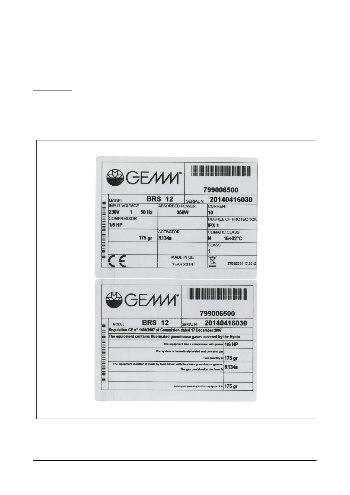
Fig. 1
Thank you for choosing one of our refrigerated base “BASIC” series, refrigerated/freezer bases for gastronomy.
Please carefully read the contents of this guide and make it available to whoever must install, use and maintain the
appliance.
1.1 – MARKING
The appliance identification plates (as shown in fig. 1 below) of all GN refrigerated bases “BASIC” series are placed on
the outer right side panel at the bottom front edge (toward the door). This position remains the same independently from
the number of the doors of the base (for 2 / 3 or 4 doors base).
BRS Rev01-IT-EN NEUTRO 12-2014 pag. 32
Page 33
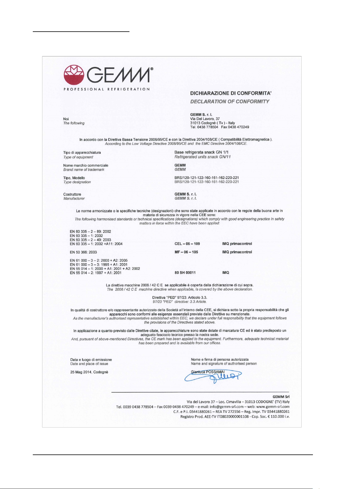
1.2 – DECLARATION OF CONFORMITY
BRS Rev01-IT-EN NEUTRO 12-2014 pag. 33
Page 34

1.3 – WARRANTY
This symbol indicates information and warnings which if not observed could damage the appliance or
compromise the safety of personnel.
This symbol indicates information and warnings regarding electrical devices which if not observed could
damage the appliance or compromise the safety of personnel.
The warranty covering the various parts of the appliance is valid from the date on the relative delivery note and is as
described in the sales agreement.
The warranty does not cover damage to the appliance caused by:
- transport and/or handling;
- operator errors;
- lack of the maintenance described in this manual;
- faults and/or breakages that cannot be traced to faulty operation of the appliance;
- maintenance operations carried out by unqualified personnel;
- improper use.
1.4 – AFTER-SALES SERVICE
Please contact the manufacturer directly for any needs regarding use, maintenance or ordering of spare parts, and specify
the identification of the appliance given on the ID plate.
1.5 – HOW TO USE AND KEEP THE MANUAL
The purpose of this manual is to provide all the information necessary to ensure proper use of the appliance in complete
safety and independence.
The manual is sub-divided into chapters with paragraphs and sub-paragraphs: the contents page is easily consulted to find
any aspect of interest.
The material in this document is provided exclusively for the purpose of information and may be altered without notice.
Although great attention is paid to drawing up the manual, the manufacturer is not responsible for damage deriving
from errors, omissions or the use made of the information herein.
Keep this manual and all the documentation in the appendices in good condition, legible and complete in all its parts; keep
it close to the equipment in an accessible place known to all operators.
1.5.1 – SYMBOLS USED IN THIS MANUAL
BRS Rev01-IT-EN NEUTRO 12-2014 pag. 34
Page 35

1.6 – PERSONNEL
Operators must not carry out operations reserved for maintenance engineers or specialised
technicians.
The manufacturer accepts no responsibility for damage deriving from failure to observe this
rule.
This manual is for the use of operators, authorized fitters and maintenance engineers.
- Appliance operator: specialised person who can operate the appliance in normal working conditions by using
the relevant controls. The operator must also be capable of carrying out simple routine maintenance (cleaning,
loading) and starting or resetting the appliance after a power failure.
- Specialised electrician: specialised electrician who has been trained by the manufacturer to work on the
appliance. The specialised electrician must be capable of installing the appliance and operating it in normal
conditions; s/he is qualified to carry out all electrical and mechanical adjustments, maintenance and repairs. S/he
is able to operate with live electrical control boxes and connector blocks.
- Qualified fork-lift operator: person qualified in handling materials on the company’s premises, holder of a licence
for the use of fork-lift trucks.
BRS Rev01-IT-EN NEUTRO 12-2014 pag. 35
Page 36
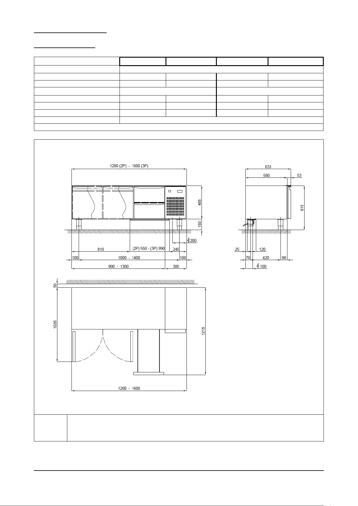
2 – MACHINE DESCRIPTION
Model
BRS - 120
BRS - 160
BRSBT - 120
BRSBT - 160
External dimensions
cm
120 (2P) / 160 (3P) x 63 x 62h
Weight
kg
n.d.
n.d.
n.d.
n.d.
Capacity
lt
170
265
170
265
Chamber temperature
°C
-2 / +8
-18 / -15
Gas
gr
R 134 a 170
R 134 a 240
R 404 a 290
R 404 a 260
Compressor power
W
230
440
230
440
Max. absorbed power
W
280
555
280
555
Input Voltage
Volt 1x230 ~ 50 Hz
Tab. 1/a
R
Alimentazione elettrica: cavo 3x1.5 mm2 completo di spina Schuko; L=4000 mm
Electricity supply: 3x1.5 mm2 wire complete with Schuko plug; L=4000 mm
Elektrischer Stromanschluss: Kabel 3x1,5 mm2 komplett mit Schukostecker; L=4000 mm
Alimentation électrique: câble 3x1.5 mm2 avec fiche Schuko; L=4000 mm
Fig. 2/a
2.1 – TECHNICAL DATA
BRS Rev01-IT-EN NEUTRO 12-2014 pag. 36
Page 37
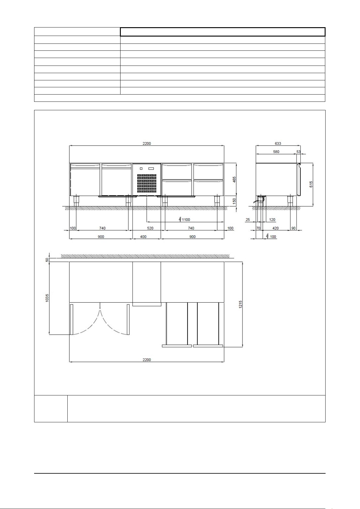
Model
BRS - 220
External dimensions
cm
220 x 63 x 62h
Weight
kg
n.d.
Capacity
lt
170 + 170
Chamber temperature
°C
-2 / +8
Gas
gr
R 134 a 280
Compressor power
W
460
Max. absorbed power
W
555
Input Voltage
Volt 1x230 ~ 50 Hz
Tab. 1/b
R
Alimentazione elettrica: cavo 3x1.5 mm2 completo di spina Schuko; L=4000 mm
Electricity supply: 3x1.5 mm2 wire complete with Schuko plug; L=4000 mm
Elektrischer Stromanschluss: Kabel 3x1,5 mm2 komplett mit Schukostecker; L=4000 mm
Alimentation électrique: câble 3x1.5 mm2 avec fiche Schuko; L=4000 mm
Fig. 2/b
BRS Rev01-IT-EN NEUTRO 12-2014 pag. 37
Page 38
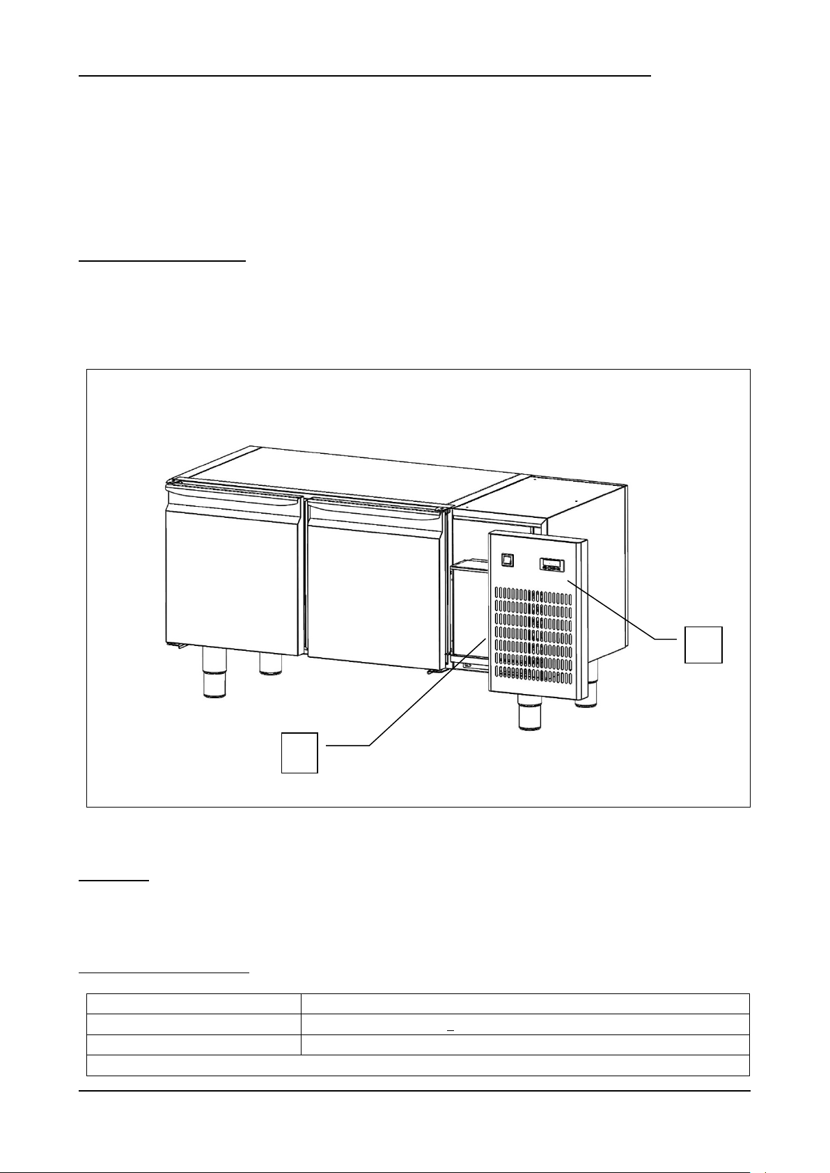
2.2 – DESCRIPTION OF THE GN REFRIGERATED BASE “BASIC” SERIES AND INTENDED USE
Fig. 3
Installation site
Kitchens, restaurants, laboratories, showrooms, bars/pubs.
Relative humidity
< 80% without condensation
Climatic class
“N” + 16 °C ÷ + 32 °C
Table 2
2
1
Essentiality and reliability are the key words that come to mind in describing the refrigerated bases in the GN “BASIC”
range. The one-piece structure features AISI 304 stainless steel both inside and outside, with 45 mm thick insulating core
made by injecting HCFC-free high-density polyurethane resins. The table interior is rounded at the bottom for easy
cleaning, the feet and rack support structure are made in stainless steel, while the door is fitted with an easily replaceable
slot-in magnetic seal, which is easy to clean and heated in the BT version.
Refrigeration is fan-assisted and controlled by digital thermostat with an electric auto-defrost feature as well as automatic
evaporation of condensation.
2.2.1 – MAIN COMPONENTS
The appliance comprises the following parts:
body;
refrigerating unit (ref. 1, fig. 3);
control panel (ref. 2, fig. 3)
2.3 – NOISE
The appliance is designed and built to keep its noise level as low as possible.
Specifically, we declare a noise level below 60 decibels.
2.4 – AMBIENT CONDITIONS
BRS Rev01-IT-EN NEUTRO 12-2014 pag. 38
Page 39
3. – SAFETY
IMPORTANT: before using the appliance, carefully read through this user’s guide and then scrupulously
follow the technical operating instructions and other instructions given in it. The operator must know
where all the control devices are positioned and their functions, as well as the specifications of the
refrigerated counter.
The refrigerated base complies with current safety laws and regulations. Misuse could, however, cause
injury to persons and damage to property.
At the time of installation all operatives must be suitably trained in accident hazards, operator safety
devices, general accident prevention regulations described in international directives and the current law
in the countries where the appliance is used. Start-up and use of the appliance must be exclusively in
the hands of trained personnel. The behaviour of operators must in any case scrupulously observe
accident prevention regulations in the country where the appliance is used.
Do not remove or tamper with the rating/identification plates fixed by the manufacturer on the appliance.
The refrigerated base must not be used if the control panel malfunctions or if any parts are damaged.
Do not obstruct the front and/or rear air vents on the appliance; do not place food to be processed up
against the ventilation grilles or air ducts, or directly on the bottom of the chamber.
Promptly report any anomalies in operation.
Use only accessories recommended by the manufacturer.
Do not expose the appliance to rain or sprays of water.
Disconnect the appliance from the electricity supply before carrying out any routine or extraordinary
maintenance which involves opening the control panel or disassembling any part of the refrigerated
base.
3.1 – GENERAL WARNINGS
The manufacturer has no responsibility in the following cases:
the maintenance plan is not carried out;
unauthorized alterations and/or operations:
spare parts used are not original;
failure to observe even part of the contents of this manual;
improper use of the appliance.
Any tampering with or unauthorized replacement of one or more appliance parts or components and use of
accessories and consumables different from the original ones can constitute a hazard and relieve the
manufacturer of any civil or penal responsibility.
If in doubt about operation of the appliance, refrain from using it and contact the manufacturer.
BRS Rev01-IT-EN NEUTRO 12-2014 pag. 39
Page 40
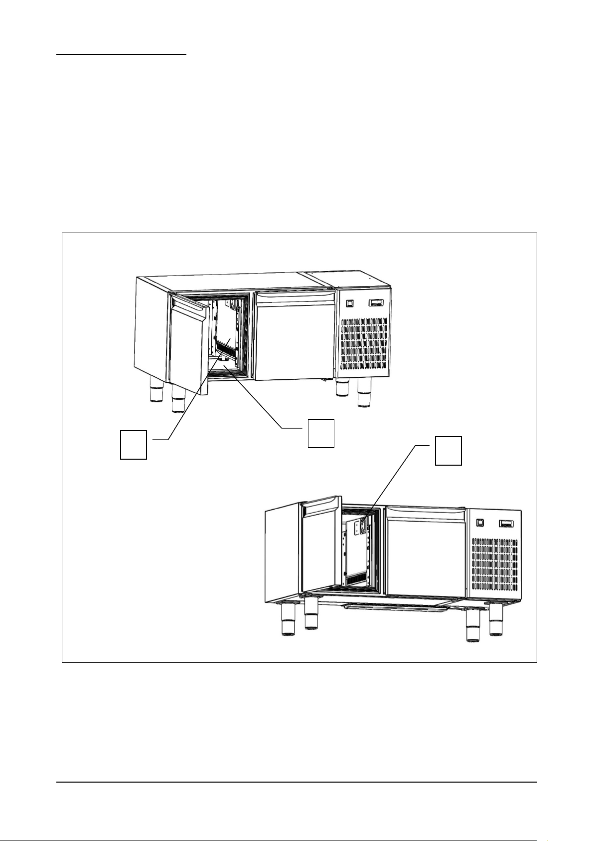
3.2 – PRECAUTIONS FOR USE
Fig. 4
3
1
2
The refrigerated bases of the “BASIC” series must not be used:
other than for the purpose described in section 2.2 “Description of the refrigerated base and intended use”;
with safety systems not working;
after badly done installation;
by untrained personnel;
when maintenance has not been carried out, or has been carried out badly;
when non-original spare parts are used;
with damaged power lead and/or electrical socket;
with obstructed air ducts (ref. 1 fig. 4);
with any food products (food or drinks) placed close to the internal ventilation grilles (ref. 3, fig. 4) or directly on
the cabinet floor (ref. 2, fig. 4).
BRS Rev01-IT-EN NEUTRO 12-2014 pag. 40
Page 41
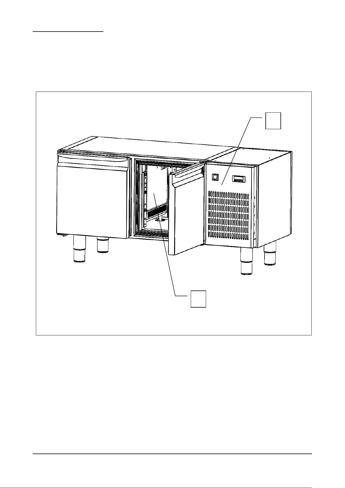
3.3 – PROTECTIVE DEVICES
Fig. 5
2
1
Personnel exposed to risks due to hazardous moving elements are protected by the presence of appropriate devices
installed on the appliance:
internal stainless steel (TH) or alloy (TG) wall covering the evaporator and the internal fans (ref.1, pic.5);
front panel covering the capacitor fan (ref.2, pic.5).
BRS Rev01-IT-EN NEUTRO 12-2014 pag. 41
Page 42
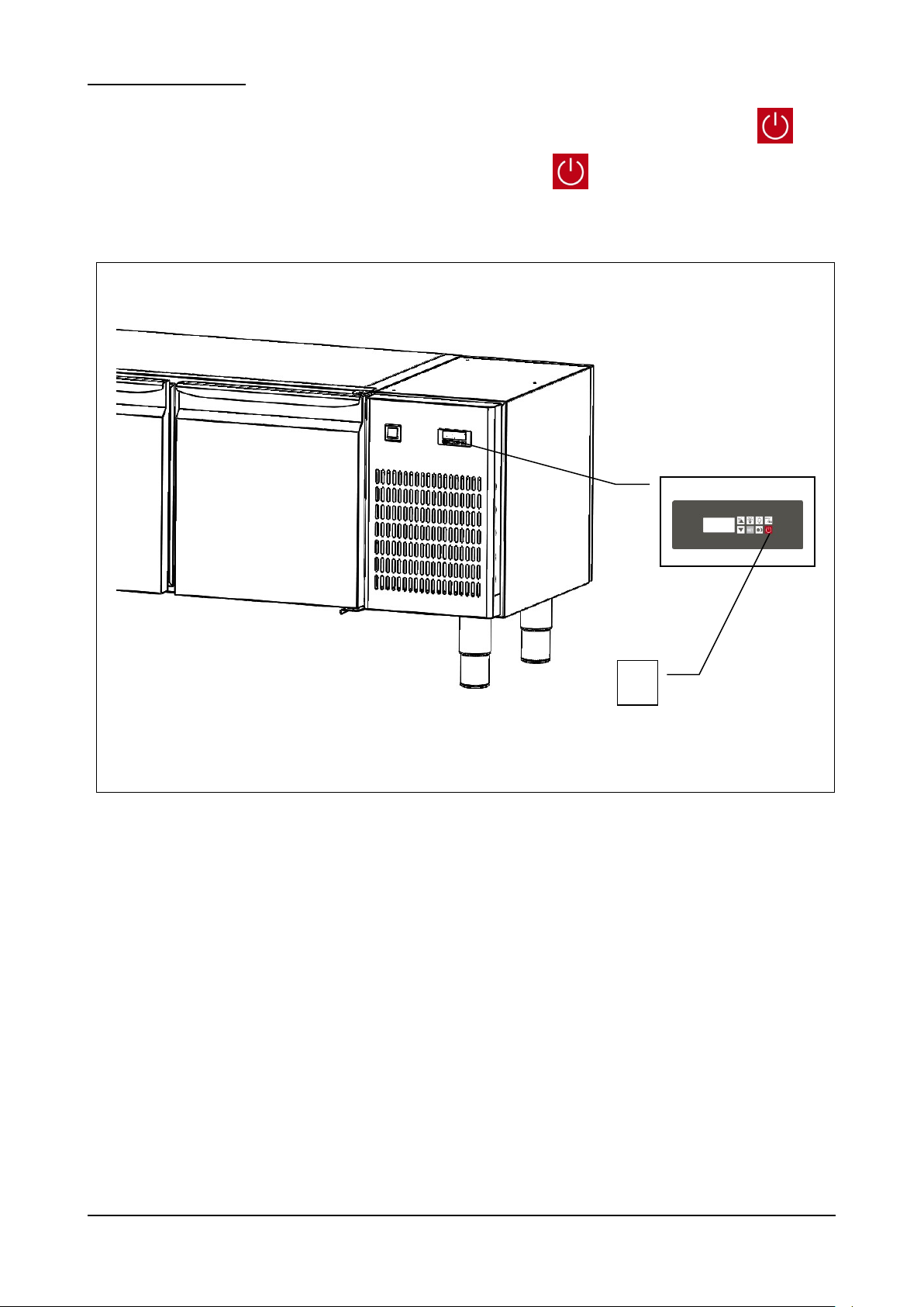
3.4 – STOP FUNCTIONS
Fig. 6
1
The appliance as a whole is controlled by a digital thermostat . The stop function is represented by the button (ref.1
pic.6). Whatever the mode of operation of the appliance, press the button to put the electronic card (PCB) to the
OFF status.
BRS Rev01-IT-EN NEUTRO 12-2014 pag. 42
Page 43
4 – TRANSPORTATION AND HANDLING
The appliance must never be overturned.
The packing must be well placed on the platform of the means of transport and secured by
appropriate ropes.
Pay close attention when lifting and positioning the refrigerated base in order to avoid serious
damage to persons or things. The manufacturer declines all responsibility if the indications for
lifting and transport the refrigerated base are not observed.
Ambient temperature must never drop below 4°C during transport.
Take care when lifting and handling the base; there is the danger of even fatal injury with loads
being moved.
All handling and lifting operations must be carried out with great caution, making sure that all
personnel is strictly at a safety distance and that no-one stands under suspended loads, be they
still or in motion.
Before starting the operation, check the whole appliance handling area to identify any
dangerous points.
Ambient temperature must never drop below 4°C during transport.
4.1 – TRANSPORTATION OF THE REFRIGERATED BASE
Suitable packaging for the type, size and weight of the appliance has been used to ensure it is not damaged during transit
till delivery to the purchaser.
The refrigerated base must be placed and maintained upright on a pallet wrapped in its own cardboard for the entire
shipping time .
The refrigerated base is consigned to the carrier packed, ready for delivery,
Once the refrigerated base has been unpacked, the packaging material must be disposed of or recycled in accordance
with the laws in force in the country where the appliance is being installed.
4.2 – HANDLING THE PACKAGED REFRIGERATED BASE
BRS Rev01-IT-EN NEUTRO 12-2014 pag. 43
Page 44
AUTHORIZED PERSONNEL
Model
BRS / BRSBT
120
BRS / BRSBT
160
BRS - 220
Dimensions
cm
120 x 63 x 62h
160 x 63 x 62h
220 x 63 x 62h
Weight
Kg
n.d. / n.d.
n.d. / n.d.
n.d.
Tab.3/a
The use of unsuitable equipment can cause accidents to those involved in the operation and/or
damage to the appliance.
The manufacturer declines all responsibility for improper non-compliant use of equipment for
lifting, transport and handling.
Specialised fork-lift truck operator.
Individual safety devices:
- safety shoes;
- safety gloves.
Personnel carrying out such operations must not wear rings, wrist watches, jewellery, loose or unfastened garments, such
as, for example, ties, torn garments, scarves, unbuttoned jackets or blouses with open zips, etc. In general, personnel
must wear safety apparel.
4.2.1 – WEIGHT AND DIMENSIONS OF THE REFRIGERATED BASE
4.2.2 – MEANS REQUIRED
- To lift the appliance use a fork-lift truck of suitable minimum capacity.
BRS Rev01-IT-EN NEUTRO 12-2014 pag. 44
Page 45
5 – INSTALLATION
Use the utmost care in handling the appliance, so as to avoid damage to persons or things.
Do not start the appliance if there are faults on the control panel or parts are damaged.
Check that the packing has not been damaged during transport.
The use of unsuitable equipment can cause accidents to those involved in the operation and/or
damage to the appliance.
The manufacturer declines all responsibility for improper non-compliant use of equipment for
lifting, transport and handling.
AUTHORIZED PERSONNEL
Specialised electrician.
Individual safety devices:
safety shoes;
safety gloves.
Personnel carrying out such operations must not wear rings, wrist watches, jewellery, loose or unfastened garments, such
as, for example, ties, torn garments, scarves, unbuttoned jackets or blouses with open zips, etc. In general, personnel
must wear safety apparel.
5.1 – PREPARATION FOR INSTALLATION
For installation prepare an area of manoeuvre suitable for the dimensions of the appliance (see fig. 2) and the chosen
lifting equipment.
The installation site must be prepared with all the connecting systems required for the appliance to work.
Choose an installation site with requisites that will allow the appliance to be used safely. The area must provide good
support, with a solid flat floor whose finish will ensure a suitable and safe working place for personnel.
Install the appliance in a place with natural and/or artificial light suitable for the operations to be carried out (in compliance
with specific regulations).
5.2 – UNPACKING
5.2.1 – MEANS REQUIRED
Use a fork-lift truck or equivalent equipment to lift the appliance.
BRS Rev01-IT-EN NEUTRO 12-2014 pag. 45
Page 46
5.2.2 – UNPACKING PROCEDURE
All the handling and unpacking operations must be carried out with extreme care, making sure
that all personnel is strictly at a safety distance and that no-one stands under suspended loads,
be they still or in motion.
AFTER INSTALLING THE APPLIANCE, WAIT AT LEAST TWO HOURS BEFORE TURNING IT ON.
The use of unsuitable equipment can cause accidents to those involved in the operation and/or
damage to the appliance.
The manufacturer declines all responsibility for improper non-compliant use of equipment for
lifting, transport and handling.
All the handling and unpacking operations must be carried out with extreme care, making sure
that all personnel is strictly at a safety distance and that no-one stands under suspended loads,
be they still or in motion.
To unpack the appliance simply remove the cardboard. Then remove the appliance from the pallet using a fork lift truck,
ensuring that the forks are inserted under the appliance.
5.3 – HANDLING THE REFRIGERATED BASE
5.3.1 – MEANS REQUIRED
See paragraph 5.2.1.
5.3.2 – HANDLING THE UNPACKED REFRIGERATED BASE
To move the base on wheels, release the brakes on the wheels and push, taking care to block the brakes again when the
appliance is in its permanent position.
To move the base on feet, lift them with a suitable fork-lift truck; the forks should be placed under the appliance, taking
care not to damage the two water tray runners.
5.4 – REFRIGERATED BASE ASSEMBLY
The refrigerated base is delivered to the customer assembled in all its parts.
BRS Rev01-IT-EN NEUTRO 12-2014 pag. 46
Page 47
6 – SETTING UP
AFTER INSTALLING THE APPLIANCE, WAIT AT LEAST TWO HOURS BEFORE TURNING IT ON.
Electrical connection must be made by a specialised electrician.
Check that the power supply voltage given on the ID plate corresponds to that available at the
installation site.
Connections must be made to current regulations; the supply mains must have an efficient
earthing system compliant with electricity regulations in the country; this is a responsibility of
the customer.
Do not make tight bends on the power lead and do not place any object whatsoever on top of
it.
If it is necessary to unplug the main supply, first make sure that the is placed on OFF.
The manufacture declines all responsibility for damage or accidents caused by failure to observe
such regulations.
Regulation carried out by unauthorized personnel may damage the appliance and expose the
operator to serious hazards. Regulation carried out by unauthorized personnel is considered
tampering with the appliance and as such null the warranty and relieve the manufacturer of any
responsibility.
6.1 – CONNECTIONS
6.1.1 – ELECTRICAL CONNECTION
ELECTRICAL CONNECTION PROCEDURE
The appliance is supplied by the manufacturer complete with power plug. Just connect the power plug to a socket at the
installation site; the system must be carried out to current regulations.
The electricity supply at the installation site must have the following requisites:
Voltage: 230 Vac
Frequency: 50 Hz
6.2 – PRELIMINARY CHECKS
The installer-electrician must instruct the operator on how to use the refrigerated base correctly and explain the basic
maintenance to be carried out.
METHOD
A specialised technician must prepare the refrigerated base for switching on for the first time, in the presence of the operator
who will use the appliance so that the operator can acquire a minimum working knowledge to help him carry out allowed
routine maintenance and cleaning.
Prior to switching on the appliance, a series of checks and controls must be carried out to prevent errors or accidents
during start up.
Check that the appliance has not been damaged during transport.
Check with special care for any damage to the electrical box, push button control panel, wiring and pipes.
Check that all external power sources have been connected properly.
Check that the machine is perfectly level.
6.2.1 – REGULATION
BRS Rev01-IT-EN NEUTRO 12-2014 pag. 47
Page 48
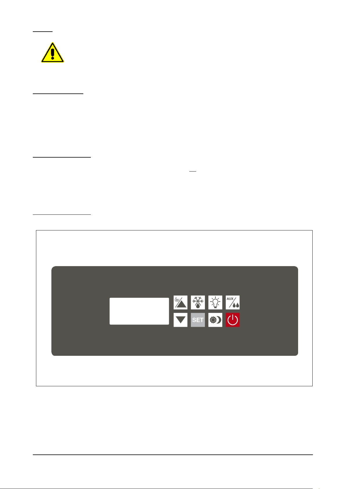
7 – USE
AFTER THE APPLIANCE HAS BEEN INSTALLED, WAIT AT LEAST TWO HOURS BEFORE
SWITCHING ON.
Fig. 7
7.1 – USE FORSEEN
The “BASIC” serier is synonymous of reliable extremely simple refrigerated base for professional gastronomy . Entirely
made in stainless steel AISI 304 accordingly with qualitatively standard, GN “BASIC” bases have a 45 mm thick insulating
core made by injecting HCFC-free high-density polyurethane resins. Refrigeration is fan-assisted and controlled by digital
thermostat with an electric auto-defrost feature as well as automatic evaporation of condensation.
7.2 – UNFORSEEN USE
Any use of the GN refrigerated base other than those described in 7.1 is not recommended. In particular, the base is not
an appliance designed for the fast cooling of food or drinks.
7.3 – CONTROL PANEL
BRS Rev01-IT-EN NEUTRO 12-2014 pag. 48
Page 49
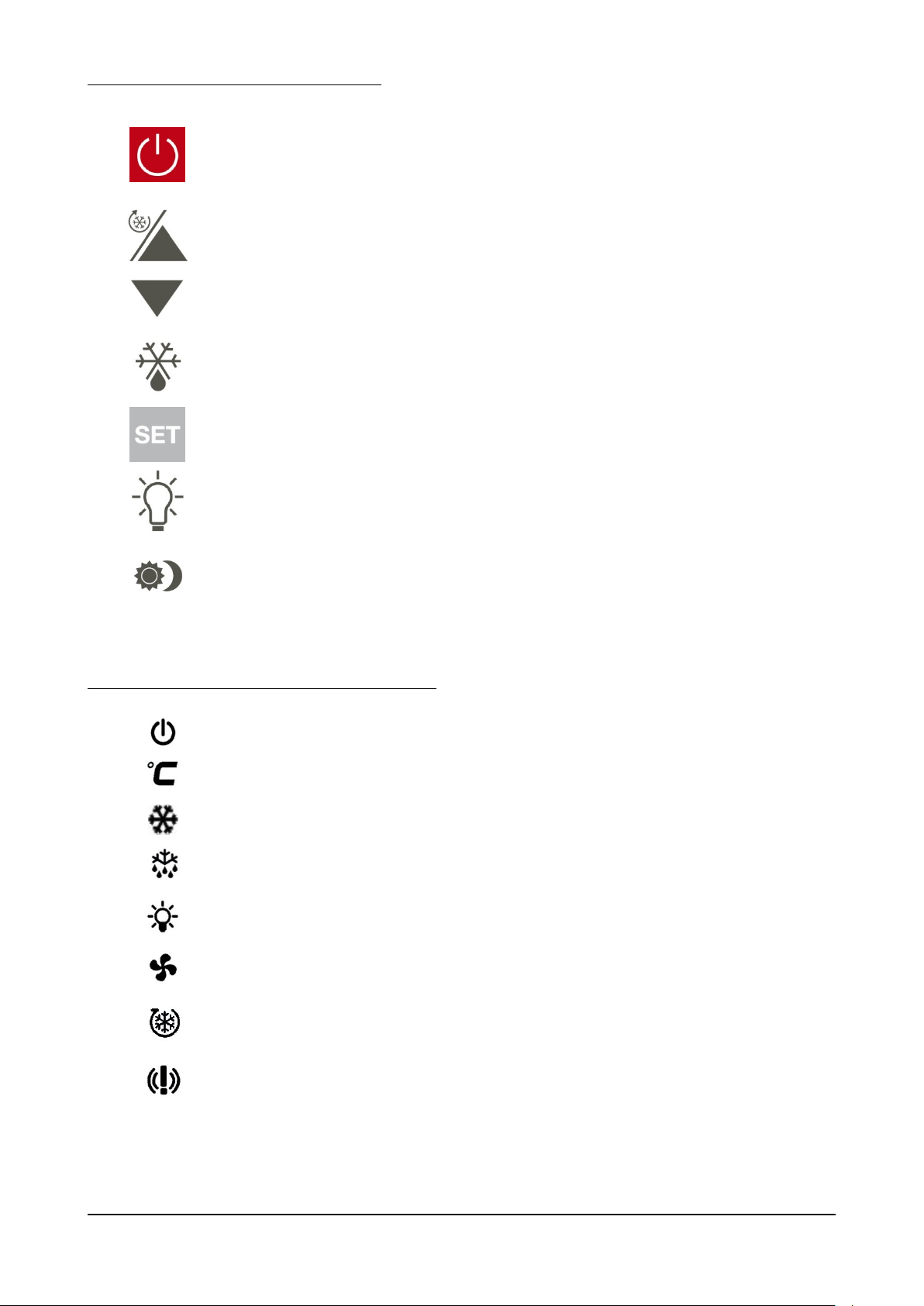
The following keys are present on the controller
0/1, ON-OFF KEY
When the appliance is OFF (0), press just once to pass to ON
(1).
When the unit is on and after having activated the keypad by
pressing and holding any key for 3 sec, press just once to switch
OFF.
UP AND DOWN KEYS
Used to increase or decrease the value that appears on the
display. With the keypad active, press and hold the UP arrow key
for 3 sec to activate the continuous timed cycle.
DEFROST KEY
With the appliance ON, press and hold for 3 sec to activate
defrost.
SET KEY
With the appliance ON and keypad active, press just once to
display the set point; press and hold for 3 sec to change the set
point.
LIGHT KEY
With the appliance ON and keypad active, press just once to
switch the interior light on or off.
ENERGY SAVING
With the appliance ON, press and hold for 3 sec to
activate “night” function of Energy saving.
OFF
Only lit when the appliance is OFF, otherwise always off.
CELSIUS
May be lit to show the temperature unit of measurement.
COMPRESSOR
Lit during normal refrigerating stages with compressor ON; off with
compressor OFF. Blinking during defrosting (temperature drop).
DEFROST
Lit during DEFROST.
LIGHT
Only lit when the cabinet interior lights are on.
FAN
Only lit when the cabinet internal fans are operating (evaporator).
CONTINUOUS CYCLE
Only lit when the continuous cycle is activated (timed cycle).
ALARMS
Only lit when an appliance malfunction or alarm is recorded by the
controller.
The following icons are present on the controller display:
BRS Rev01-IT-EN NEUTRO 12-2014 pag. 49
Page 50

7.4 – CONTROLS
As a whole the appliance is controlled by a rear panel digital thermostat.
As soon as the appliance is connected to the electricity supply, the display lights up completely for a lamp test lasting a
few seconds. At the end of the lamp test, the display goes automatically to how it was before the appliance was switched
off, for example if a cycle was in progress at that time, the cycle will restart from the point it was interrupted.
With the PCB OFF, the display is not lit except for the icon . Upon pressing key the icon goes out and the
display comes ON showing the temperature in the cabinet.
Use the commands on the thermostat, helped by the indications on the display, to activate the various appliance functions.
If the buzzer sounds for any reason whatsoever, it may be muted by simply pressing any key.
Whatever the status of the appliance, after having activated the keypad, pressing the key puts the PCB to OFF.
7.5 – PREPARING FOR USE
Before using the appliance, the inside of the cabinet should be thoroughly cleaned.
When switching on after installation or if the appliance has not been used for a long time, it is a good rule to let it operate
empty until the set temperature has been reached.
To get the best performance from the refrigerated cabinet, arrange the stored products so that air can circulate properly:
do not obstruct the refrigerating unit intake, do not lay the food and drinks on top of each other and distribute the load
evenly.
Do not load the appliance with more than the allowed quantities, do not put in food or drinks having a temperature above
the indicated design room temperature and avoid pointlessly opening the door otherwise the efficiency of the refrigerating
unit will be reduced.
BRS Rev01-IT-EN NEUTRO 12-2014 pag. 50
Page 51
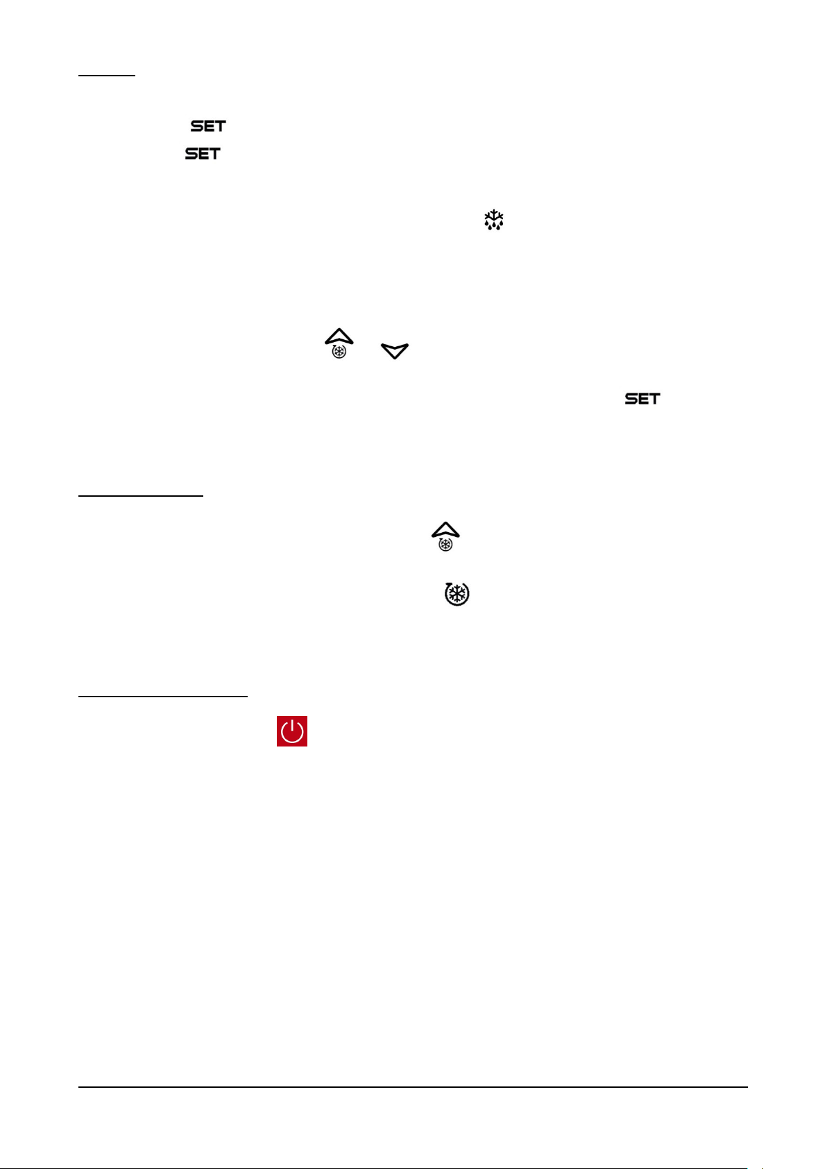
7.6 – USE
- Press the key to display the set-point and change it if necessary;
press the key just once to display the set temperature, which can be changed by pressing and holding for
3 sec the same key and then using the up and down arrow keys.
- A manual defrost can be selected; press and hold for 3 sec the key and if the evaporator temperature is no
higher than +8°C, a manual defrost phase is activated. This phase ends either when the time of 20’ has elapsed
or when the temperature measured by the evaporator sensor is (+8/+5°C Tn/BT). The automatic defrost,
managed by the thermostat, takes place once every 8H for a max. of 20’ during which time the readout dEF is
shown on the display.
- With the keypad active, press keys and just once to display the maximum and minimum temperature
respectively, which are recorded by the sensor inside the cabinet. The displayed values are preceded by the
readouts LO and HY respectively. To reset this stored value, press and hold for 3 sec the key at the time
it is displayed. On the display this reset is preceded by the readout RST (reset).
7.6.1 – SPECIAL USE
- With the keypad active, press and hold for 3 sec the key to activate the CONTINUOUS CYCLE phase.
This phase lasts (1H) at a temperature (-2/-21°C TN/BT). These values are factory set in the controller. Unlike
the normal refrigerating phase, in this case the symbol on the display is lit. When the set time (1H) has
elapsed, the symbol will go out and the appliance will start once again to operate with the previous set point.
7.6.2 – LONG IDLE PERIODS
Turn the machine OFF by pressing for three seconds, then unplug.
Clean the machine thoroughly (see paragraph 8.2) and make sure the door is left open at the end of the operation and
throughout the idle period.
BRS Rev01-IT-EN NEUTRO 12-2014 pag. 51
Page 52
8 – MAINTENANCE
Contact the manufacturer for any anomalies not described in this manual; contact the manufacturer
also for any doubts during the maintenance operations described herein. Maintenance carried out
by unauthorized personnel may damage the appliance and expose the operator to serious hazards.
Maintenance carried out by unauthorized personnel is considered tampering with the appliance and
therefore nulls the warranty and relieves the manufacturer of any responsibility.
Any routine or extraordinary maintenance operation that requires the electric box to be
opened or the machine to be dismantled, even partially, must be carried out only after the
appliance has been switched off and unplugged.
Any maintenance operations carried out on a live machine may cause people serious
accidents which may also be fatal.
The safety devices must be deactivated only by authorized personnel, who will guarantee safety for
people and avoid damage to the machine. The safety devices must be carefully activated again after
carrying out maintenance.
During maintenance or repairs unauthorized persons must keep a safe distance from the appliance.
Observe the intervals prescribed or indicated in this manual for making inspections.
At the end of maintenance or repairs the appliance can be started only after the specialist engineer
has made sure that:
- all the work has been fully carried out;
- the safety systems are active;
- the appliance is working perfectly;
- no-one is working on the appliance.
Component
Type of operation
Timing
Responsibility
Method
Chamber
Cleaning
When needed
Appliance operator
See para. 8.2.2
External part
Cleaning
When needed
Appliance operator
See para. 8.2.3
Condenser
Cleaning
Every 60 days
Appliance operator
See para. 8.2.4
Table 4
8.1 – SPECIAL PRECAUTIONS
8.2 – ROUTINE MAINTENANCE
8.2.1 – ROUTINE MAINTENANCE TABLE (TAB. 4)
8.2.2 – CLEANING THE CHAMBER
Carry out this operation whenever necessary.
APPLIANCE STATUS:
- ON/OFF button on OFF position;
- power supply plug disconnected from the mains.
BRS Rev01-IT-EN NEUTRO 12-2014 pag. 52
Page 53
AUTHORIZED PERSONNEL
Use exclusively water and non-abrasive neutral detergent for cleaning. The use of different products
could damage the surface of the appliance and compromise the quality and healthiness of the
product being processed.
Do not use abrasive sponges.
Do not clean the device through cloths that may leave lint and do not use direct water jets on the
device.
Fig. 8
1
2
Appliance operator.
METHOD
Carefully clean the cabinet interior, the contact surfaces of where the door closes (ref. 1 fig. 8) and the gasket (ref. 2 fig.
8) using a sponge soaked with neutral detergent, neither of which must be abrasive. Rinse thoroughly using a clean sponge
soaked with water and then wipe dry using a clean cloth.
Proper cleaning of the appliance interior prevents the formation of unpleasant odours, which could impair the product to
be stored there.
BRS Rev01-IT-EN NEUTRO 12-2014 pag. 53
Page 54

8.2.3 – CLEANING THE OUTSIDE OF THE APPLIANCE
Use exclusively water and non-abrasive neutral detergent for cleaning. The use of different products
could damage the surface of the appliance and compromise the quality and healthiness of the
product being processed.
Do not use abrasive sponges.
When cleaning do not use cloths that leave lint.
Carry out this operation whenever necessary.
APPLIANCE STATUS:
- ON/OFF button on OFF position;
- power supply plug disconnected from the mains.
AUTHORIZED PERSONNEL
Appliance operator.
METHOD
Clean the outer surface of the appliance (steel base and panelling), using a non-abrasive sponge soaked in neutral
detergent. Rinse with a sponge soaked in water and dry with a clean cloth.
BRS Rev01-IT-EN NEUTRO 12-2014 pag. 54
Page 55
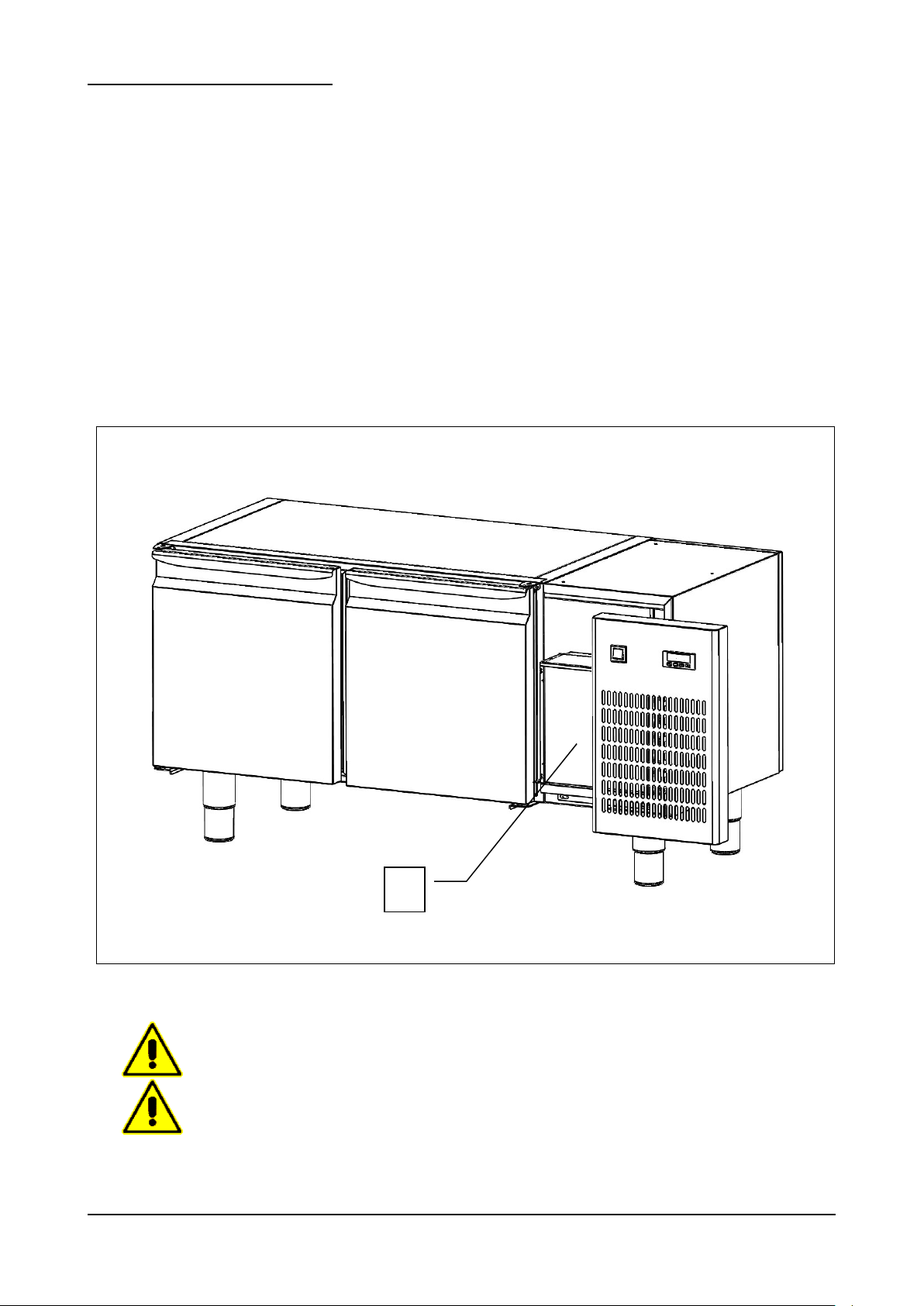
8.2.4 – CLEANING THE CONDENSER
Fig. 9
The condenser has sharp edges. When carrying out the operations mentioned above, wear
safety gloves, goggles and face masks.
Do not use direct water jets to clean the appliance.
1
Carry out this operation every 60 days.
APPLIANCE STATUS:
- ON/OFF button on OFF position;
- power supply plug disconnected from the mains.
AUTHORIZED PERSONNEL
Appliance operator.
METHOD
For trouble-free efficient refrigerating unit operation, the air-cooled condenser (ref. 1 fig. 9) must be always kept clean so
that air circulates freely. Cleaning must be done once every 60 days at the most. Use non-metallic brushes to clean,
ensuring that all the dust and fluff is removed from the fins. We recommend using a vacuum cleaner so as to avoid dust
being dispersed into the environment. If there are greasy deposits, remove them using a small brush soaked in alcohol.
DO NOT SCRAPE THE SURFACES WITH SHARP POINTED OR ABRASIVE OBJECTS.
BRS Rev01-IT-EN NEUTRO 12-2014 pag. 55
Page 56

8.3 – EXTRAORDINARY MAINTENANCE
Contact the manufacturer to dismantle the appliance in any way.
If the appliance needs extraordinary maintenance, or if operating anomalies occur that are not described in this manual,
contact the manufacturer.
8.4 – OPERATING ANOMALIES AND FAULTS
It is important to remember that whatever machine status is, pressing the button turns it OFF.
When any operating anomaly occurs the buzzer sounds intermittently and abbreviation appears on the display. Whatever
the reason for the buzzer, it can be silenced by pressing any button.
8.4.1– ALARMS
The following alarms could appear on the display:
- “ HA ” HIGH cabinet internal temperature alarm. This alarm is triggered during the normal refrigerating cycle,
after the delay time, but has no direct effect. The alarm message disappears as soon as the cabinet internal
temperature falls to within the set point. If, however, the alarm persists, have the appliance checked by a
specialised technician.
- “ LA ” LOW cabinet internal temperature alarm. This alarm is triggered during the normal refrigerating cycle, after
the delay time, but has no direct effect. The alarm message disappears as soon as the cabinet internal
temperature falls to within the set point. If, however, the alarm persists, have the appliance checked by a
specialised technician.
8.4.2– TROUBLESHOOTING
The following malfunctions are acknowledged by the electronic controller:
- “P1” CABINET sensor error. The error is triggered during the normal refrigerating cycle just a few seconds after
the sensor starts to malfunction. The cycle is not stopped, but the compressor operates on an alternating basis
(ON/OFF) to ensure that cabinet temperature is maintained. The error message disappears just a few seconds
after the sensor starts operating regularly again. If the error persists, before replacing the sensor, first check the
connections.
- “P2” EVAPORATOR sensor error. The error is triggered during the normal refrigerating cycle just a few seconds
after the sensor starts to malfunction. The refrigerating cycle is not stopped by the error and the compressor
operates regularly, but the subsequent defrost cycles will be carried out on a time basis rather than according to
the temperature given by the actual sensor. The error message disappears just a few seconds after the sensor
starts operating regularly again. If the error persists, before replacing the sensor, first check the connections.
9 – DISMANTLING
BRS Rev01-IT-EN NEUTRO 12-2014 pag. 56
Page 57
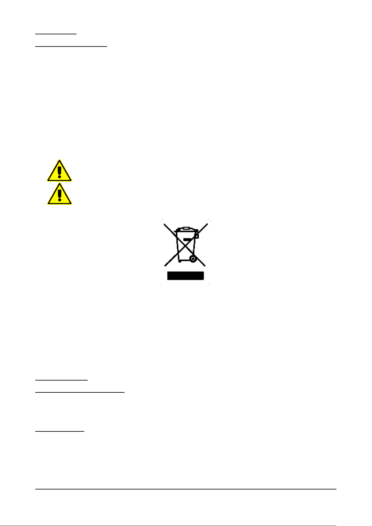
10 – DISPOSAL
TAKE CARE: THE APPLIANCE CONTAINS REFRIGERANT GAS THAT MUST BE
CONTROLLED AND RECOVERED ACCORDING TO THE REGULATIONS OF THE COUNTRY
IN WHICH DISPOSAL WILL TAKE PLACE.
Consult the fitter for any dismantling requirements.
10.1 – DISPOSAL METHOD
APPLIANCE STATUS
- electronic circuit board in OFF position;
- power supply plug disconnected from the mains.
METHOD
The appliance is made of ferrous materials, electronic components and plastics. If it needs to be disposed of, separate
the various components according to the material of which they are made, to simplify separate waste collection or re-use
of the parts. The appliance must be disposed of separately from urban waste.
No special instructions apply to the dismantled appliance. Dispose of it through the special operators or return to the
dealer, if the law provides for this (also see “Information to users regarding waste disposal in the European Union” below).
For disposal consult the laws applicable in the country where the appliance is used (also see “Information to users regarding
waste disposal in the European Union” below).
INFORMATION TO USERS REGARDING WASTE DISPOSAL IN THE EUROPEAN UNION
The symbol of a crossed waste bin on the appliance indicates that at the end of its working life the product must be collected
separately from other waste.
Therefore, at the end of the product’s working life the user must take it to a suitable centre for the collection of electronic
and electrical waste, or return it to a dealer when purchasing a new appliance of the same type.
Suitable separate waste collection of unwanted appliances and their forwarding to treatment, recovery and
environmentally friendly disposal makes it possible to avoid potential negative effects on the environment and human
health, and assists recycling and recovery of materials.
Unauthorized disposal of the product by the user is punished by the application of fines established by the countries in
which the appliance is disposed of.
11 – SPARE PARTS
11.1 – ORDERING SPARE PARTS
Contact authorized dealer or the manufacturer to order spare parts.
12 – APPENDICES
The appliance comes with the following appendices:
- Declaration of conformity
- Electrical diagram
- Electrical approval report
- Assessment of vacuum, leakage and gas loading for cooling unit.
BRS Rev01-IT-EN NEUTRO 12-2014 pag. 57
Page 58
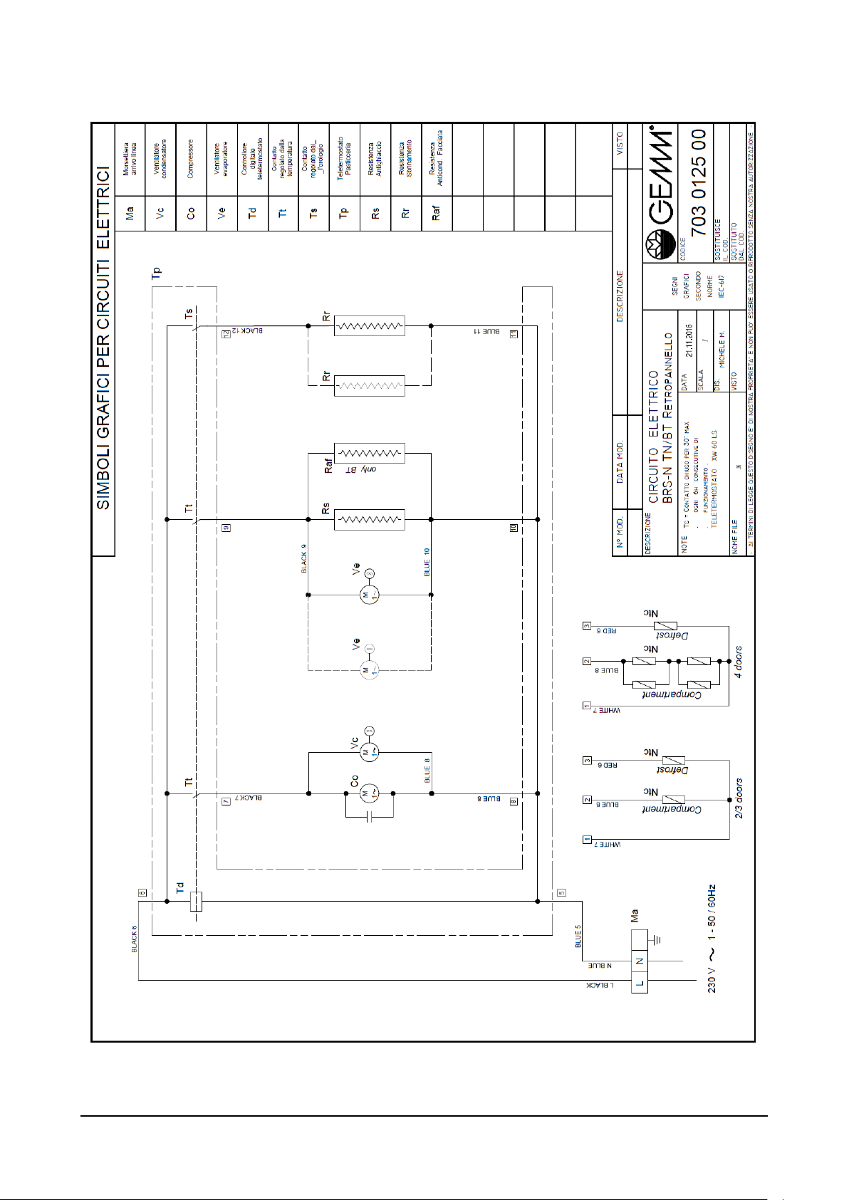
BRS Rev01-IT-EN NEUTRO 12-2014 pag. 58
Page 59

NOTE
BRS Rev01-IT-EN NEUTRO 12-2014 pag. 59
Page 60

 Loading...