

Lotus Green Genie 2500, Green Genie 3500, Green Genie 6500, Green Genie 24000, Green Genie 12500 Installation And Maintenance Instructions Manual
...
to the hosetail. If a blue-violet coloured light is reflected on to the paper, then the lamp is working
Model
UVC
Product
Quartz
Product
Replacement
Product
Flocor
Product
Filter Maintenance
Green Genie
Wattage
Code
Sleeve
Code
Foam Set
Code
Media
Code
Kit Code
25007UVT78QS8
2000 Single
TFGS2000
Pack 1000
FLCS
FMKGG25
350010UVT108QS8
3/6000 Set
TFGS2000S
Pack 1000
FLCS
FMKGG35
650018UVT188QS8
3/6000 Set
TFGS2000S
Pack 1000
FLCS
FMKGG65
1250018UVT188QS8
12000 Set
TFGS12000S
Pack 1000
FLCS
FMKGG125
2400025UVT2515QS15
24000 Set
TFGS24000S
Pack 2000
FLCDIY
FMKGG24
48000
2 x 25
UVT25
2 x 15
QS15
48000 Set
TFGS48000S
Pack 2000
FLCDIY
FMKGG48
correctly. The replacement should be a Germicidal Ultra Violet Lamp.
Remember the lamp emits harmful UV-C radiation so the burning lamp should never be
observed.
The UV Tube Should be replaced every year (Around March - April). Clean and check
the quartz tube for any sign of damage or deterioration - Replace if necessary. Also
Check the UV Housing/Body for any sing of deterioration and again, replace if
necessary.
Spare Parts
For optimum performance we recommend the use of genuine Green Genie
replacement parts. If you have difficulty obtaining parts please contact us.
REEN ENIE
REEN ENIE
REEN ENIE
REEN ENIE
REEN ENIE
GG G
GG G
GG G
GGG
GG
Combined Ultra Violet
& Pond Filtration System
INSTALLATION AND
MAINTENANCE INSTRUCTIONS
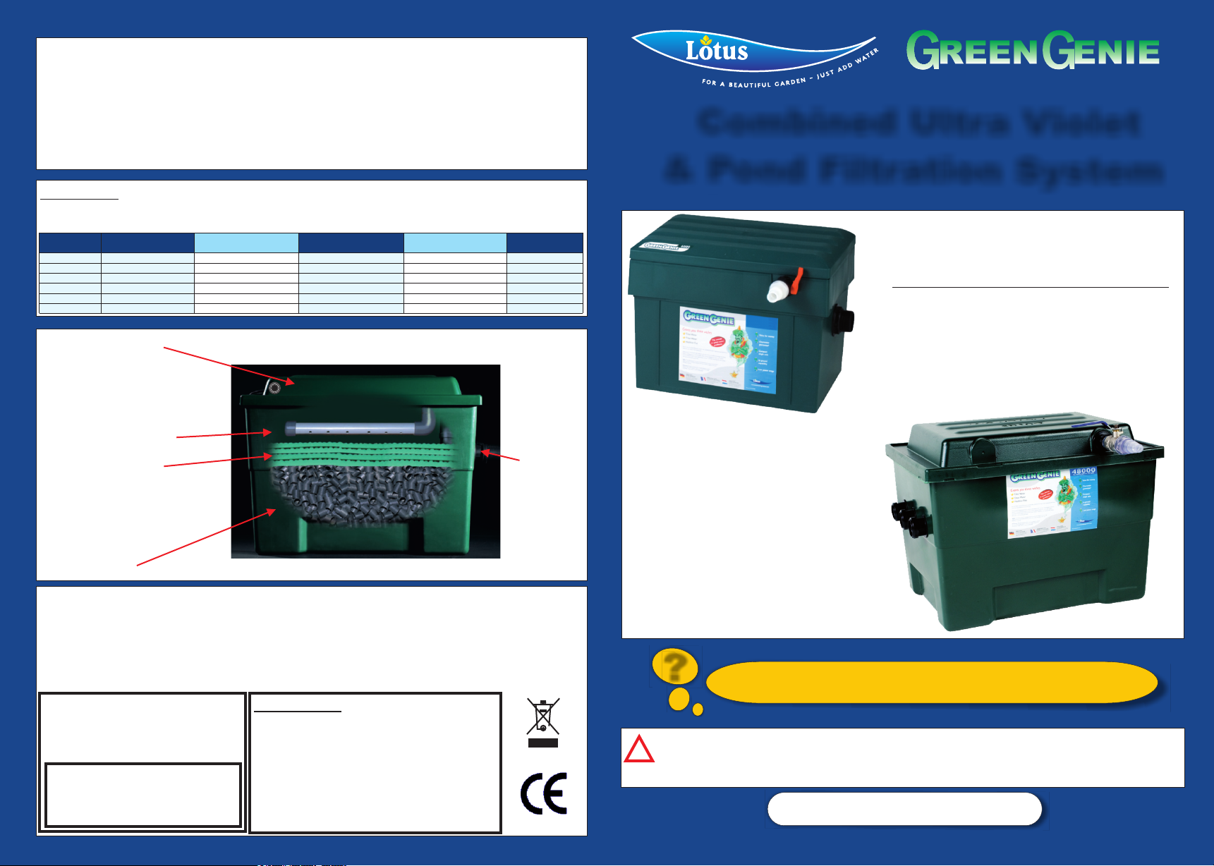
UV Compartment
Inlet
Spray Bar
Foam Set
Flocor™
Your Green Genie filter is guaranteed against failure due to defective workmanship or materials for a period of 12
months from the date of purchase. Failure caused by accidental damage, misuse, neglect or used in liquids other
than cold water are excluded from this guarantee. If a failure occurs during this period, a purchase receipt must
be produced. The unit will be either repaired or replaced at the companies option. The company cannot accept
any additional claims for consequential losses. All “ware and tear” items are excluded from this guarantee i.e
Filter Media, UV Lamp, Quartz Tubes and O Rings. This guarantee does not affect your statuary rights.
This unit is manufactured
Guarantee
Dealers Stamp:-
Outlet
in the EEC and conforms to CE
Regulations
Lotus Water Garden Products Ltd.
Eastleigh,
United Kingdom.
2500
3500
6500
12500
24000
48000
! Safety Instructions
! Installation
! Electrical
! Maintenance
! Spare Parts
! Warranty
?
Your filter may take 3-6 weeks to fully mature with
beneficial bacteria.
Important! Plastic fittings have been tightened to a "Factory Setting", however
!
in the course of transit and retail display, some fittings may require further
tightening. Hand tighten only.
www.lotuswgp.com
Safety/Installation/Electrical Instructions for all models
WHY FILTER?
Pond pollutants are introduced via an accumulation of solids settling at the bottom. These can be
categorised into two groups. I. Fish waste products - faeces, ammonia, dissolved carbon dioxide,
etc. 2.. Decaying vegetation and uneaten fish food.
The solids quickly dissolve into the pond producing harmful bi-products, which are hazardous to
fish health and may cause the water to become cloudy. Sunlight encourages algae, which makes
the pond water green. The Green Genie Biological Filter and Ultra Violet Steriliser is designed to
provide clean, clear water. The Biological effect ensures that the pond water is kept free of
pollutants that can kill fish and plant life. The UV kills algae and harmful bacteria thereby making
the pond water clear.
MECHANICAL FILTRATION
Mechanical filtration simply means the removal of the solids and prevention of their return to the
pond. This is achieved by passing the water over layers, or layer of foam in the bio-filter.
BIOLOGICAL PURIFICATION
This is achieved by colonising the plastic filter medium with 'friendly' bacteria and microorganisms which, when mature, digest pollutants thus neutralising harmful ammonia and nitrates.
UV STERILISATION
This occurs when the UV light penetrates the water as the water passes through the water
chamber. It kills the algae and harmful bacteria thereby making the pond water clear.
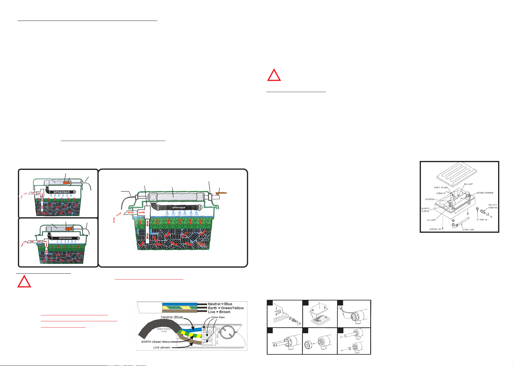
INSTALLATION - THIS APPLIANCE IS NOT SUBMERSIBLE
Connect a hose from the pump to the multi hosetail fitting on the top. The outlet water should be
routed back to the pond. On initial set up allow the unit to operate for a week before
switching on the electricity supply to the ultraviolet steriliser. This allows the filter to be
colonised by friendly bacteria. Always run 24 hours a day for maximum efficiency.
MODELS:
2500
3500
6500
Outlet
to Pond
MODEL:
12500
Outlet
to Pond
*** Wear & Tear
Items
UV/Water
Chamber
UV/Water
Chamber
VariFlow Valve**
Water Inlet
VariFlow Valve**
Water Inlet
To Mains
* See Electrical
Instructions
Inside
***Filtration
Foam Dimple Side Up
Filter Media
To Mains
* See Electrical
Instructions
Inside
***Filtration
Foam Dimple Side
Up
Filter Media
MODELS:
24000
48000
To Mains
* See Electrical
Instructions
Inside
*** Wear & Tear
Items
Outlet
to Pond
Overflow
ILLUSTRATION PURPOSES ONLY
UV/Water
Chamber
ALL IMAGES ARE FOR
** VariFlow Valve where fitted.
Water Inlet
VariFlow Valve**
***Filtration
Foam Dimple Side Up
Filter Media
Electrical Connection
The mains electricity supply MUST BE DISCONNECTED before Attempting
Installation/maintenance or handling of any kind.
!
1). This unit is designed for permanent installation to the mains.
2). The power supply should be
earthed and fused at 3amps.
3). Warning: A residue Circuit
Device (RED) Must be fitted to
Push down to insert
cable, release to secure.
the mains supply.
4). For permanent installation into
the mains, it is necessary to
comply with the regulations of the
Local Electrical Authority.
5). Consult a qualified electrician if in doubt about any aspect of electrical wiring.
6). The Wires in the cable are colour coded as follows:
Brown - Live
Green/Yellow - Earth
Blue - Neutral
7). If you need to extend the cable on this unit, you should use a suitable length of
3 core cable and a Lo t u s wa t e r p r o of (I P 68) ca b le co n n ector. (A s k yo u r
retailer).
WARNING: Never look directly at the U.V. bulb when it is switched on.
Th e UV li ght g enera t ed b y the b u lb c a n c a use d amage to ey e s and
!
skin. The Uni t is supplied With a transluce nt hosetail whic h wil l glow
allowing you to see that the U.V. is Working.
Maintenance for all Models
CLEANING
The efficiency of the filter depends on the foam and the Flocor™ being colonised. The foams should not be
cleaned unless water is passing down the overfiow pipe. Usually only the top layer needs to be cleaned.
Remove and shake clean whilst hosing with clean water. The Flocor filter medium should never be cleaned:
however it can be removed to facilitate the removal of silt from the bottom of the filter box. Please note that
the foam should be replaced every year.
ULTRA VIOLET STERILISER MAINTENANCE
When installing your Green Genie, if you need to use an extension lead use only the correct cable and
waterproof (IP68) or weatherproof (IP67) cable connectors. Remember that pets and wildlife often damage
cable, so it is advisable to run your cable through a length of hose and protect the connectors with an
arrangement of rocks or bricks.
No routine maintenance is required. Routine replacement of the lamp is recommended no later than 8000
hours, or 12 months, whichever is sooner.
REPLACING BULB & QUARTZ SLEEVE
(all "wear and tear" items)
Models 2500, 3500 & 6500: (RIGHT)
1) Isolate Steriliser from mains supply and switch off Genie.
2) Remove the two lid-retaining (self-tapping) screws.
3) Remove Genie lid.
4) Undo the hosetail by turning anti-clockwise.
5) Remove spray bar by unwinding anti-clockwise.
6) Separate the base from the lid. Pull the cable through as
you do so (remove hosetail on 12500 model).
7) Disconnect the lamp holders and pull out the bulb from
housing.
REMOVING THE QUARTZ SLEEVE
Models:2500, 3500 & 6500
8) Unscrew the two compression fittings from the ends of the water chamber and remove '0'
rings.
9) Slide out quartz sleeve; handle with care as it is brittle. Clean the quartz sleeve with
domestic acid or ammonia based cleaning solution rinsing thoroughly afterwards. If quartz
sleeve is excessively scratched, then replace. Periodically check the white UV Body/Bodies,
as they may need replacing if they show signs of deterioration.
10) Refit the quartz sleeve with the 'O' rings and tighten up the compression fittings by hand.
11) Replace the lamp and refit the lamp holders.
REPLACING UV BULB & QUARTZ SLEEVE - Models: 12500, 24000 & 48000
1. 2.
3.
I, Remove hosetail & seal/washer.
2, Remove push clips and lid.
3. Remove lamp holders from UV bulb,
4, Remove UV bulb,
4.
5.
6.
5, Unscrew endcaps at each end of UV chamber.
6, Remove '0 rings' and remove quartz sleeve, To reassemble reverse the above procedure,
If you are unsure whether or not the unit is working,
place a piece of white paper or card at the end close
 Loading...