

Losi XXX-S Sport User Manual
OWNER'S
MANUAL
Carefully read through all instructions to familiarize yourself with the parts, construction techniques, and
tuning tips outlined in this manual. Being able to grasp the overall design of your new XXX-S Graphite Plus
touring car before beginning the construction process will ensure a smooth assembly.
Take your time and pay close attention to detail. Keep this manual for future reference.
Team losi, Division of Horizon Hobby inc.,
4710 Guasti Rd., Ontario CA 91761
phone: (909) 390-9595 / Fax: (909) 390-5356
www.TeamLosi.com / feedback@TeamLosi.com
MADE IN THE UNITED STATES OF AMERICA
P/N 800-0193
JAC, RWW
Welcome Team Losi XXX-S Owner!
Thank you for selecting Team Losi and the XXX-S Graphite Plus as your new racing sedan. As you will see, we have made
every effort to design and produce a kit that is not only the most competitve, but easy to build and maintain. The simple bagby-bag assembly sequence and unmatched easily followed instructions, combined with Team Losi's world famous qualityfitting parts, should make building your new XXX-S a most enjoyable project.
Before you open the first bag or start any assembly, please take a few moments to read completely through the following
instructions. This will familiarize you with the various parts as well as the tools you will need. Taking an extra moment before
starting can save you a good deal of time and assure proper assembly.
Once again, thank you for choosing Team Losi.
Good luck and good racing!
1. INTRODUCTION
XXX-S COMPLETED KIT DIMENSIONS
Overall Length: 16-5/8" Front Width: 7-7/16" Rear Width: 7-15/32" Height: 4-3/4"
Wheelbase: 10-1/8" All dimensions at ride height. Weight will vary depending on accessories.
NOTES & SYMBOLS USED
Step A-1
This is a common step number found at the beginning of each
new illustration throughout the manual.
q 1. Each step throughout the entire manual has a check box to the
left of it. As you complete each step, mark the box with a check. If you
need to take a break and return to building at a later time you will be
able to locate the exact step where you left off.
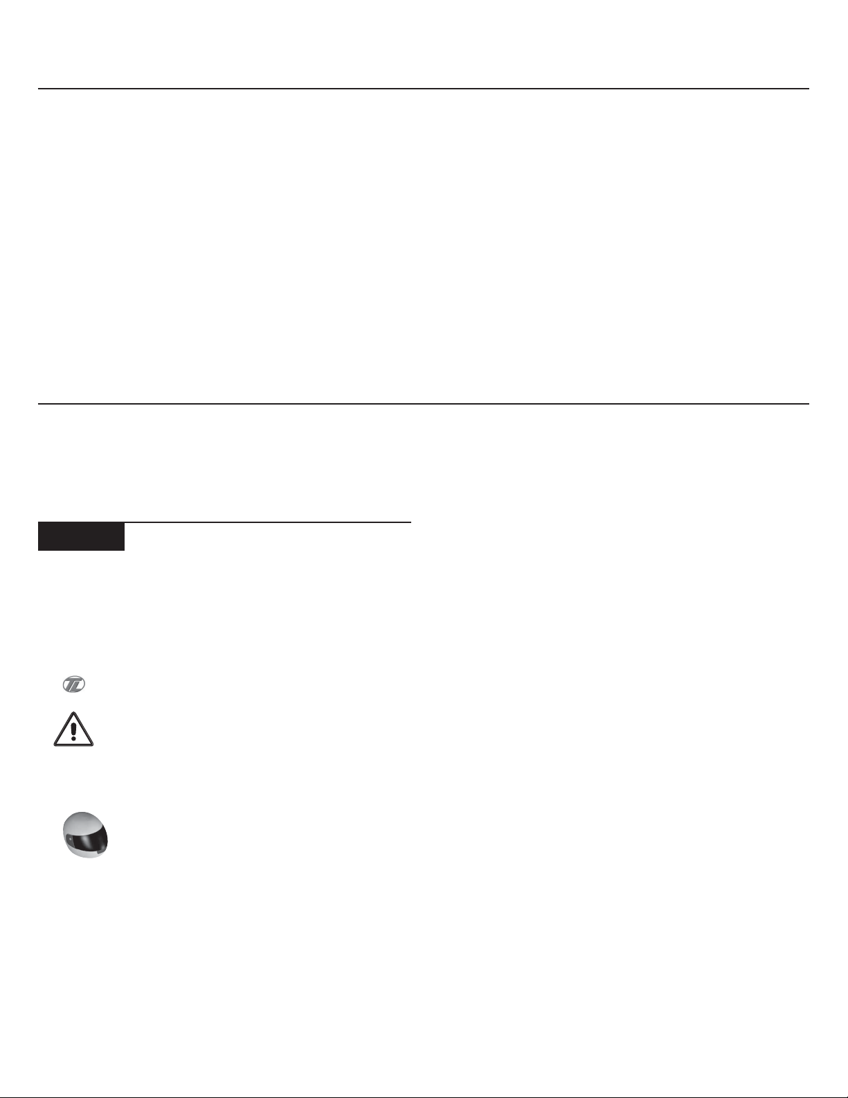
This is a common note. It is used to call attention to specific
details of a certain step in the assembly.
IMPORTANT NOTE: Even if you are familiar with Team
Losi kits, be sure and pay attention to these notes. They point out
very important details during the assembly process. Do not ignore
these notes!
In illustrations where it is important to note which
direction parts are facing, a helmet like this one will be included in the
illustration. The helmet will always face the front of the car (as the
driver would sit). Any reference to the right of left side will relate to
the direction of the helmet.
KIT/MANUAL ORGANIZATION
The kit is composed of different bags marked A through H. Each
bag contains all of the parts necessary to complete a particular section of the XXX-S. Some of these bags have subassembly bags within
them. It is essential that you open only one bag at a time and follow
the correct assembly sequence, otherwise you may face difficulties
in finding the correct part. It is helpful to read through the instruc-
tions for an entire bag prior to beginning assembly. Key numbers (in
parenthesis) have been assigned to each part and remain the same
thoughout the manual. In some illustrations, parts which have already been installed are not shown so that the current steps can be
illustrated more clearly.
For your convenience, an actual-size hardware identification
guide is included with each step. To check a part, hold it against the
silhouette until the correct part is identified. In some cases extra
hardware has been supplied for parts that may be easy to lose.
The molded parts in the XXX-S are manufactured so that they
interlock. When screws are tightened to the point of being snug, the
parts are held firmly in place. For this reason it is very important that
screws not be overtightened in any of the plastic parts.
To ensure that parts are not lost during construction, it is recommended that you work over a towel or mat to prevent parts from
rolling away.
IMPORTANT SAFETY NOTES
1. Select an area for assembly that is away from the reach of small
children. Some parts in this kit are small and can be swallowed by
children, causing choking and possible internal injury.
2. The shock fluid and greases supplied should be kept out of
childrens' reach. They are not intended for human consumption!
3. Exercise care when using any hand tools, sharp instruments,
or power tools during construction.
4. Carefully read all manufacturers' warnings and cautions for
any glues, chemicals, or paints that may be used for assembly and
operating purposes. When you are using glues, chemicals, and paints
you should always wear eye protection and a mask.
i

TOOLS REQUIRED
Team Losi has supplied all necessary allen wrenches and a special assembly wrench that is needed for assembly and turnbuckle adjustments.
The following common tools will also be required: Needle-nose pliers, regular pliers, medium grit sandpapper, hobby knife, scissors, and body
cutting/trimming tools. A soldering iron may be necessary for electrical installation. 3/16", 1/4", and 11/32" nut drivers are optional.
RADIO/ELECTRICAL
A suggested radio layout is provided in this manual. Your high-performance R/C center should be consulted regarding specific questions
pertaining to radio/electrical equipment.
HARDWARE IDENTIFICATION
When in question, use the hardware identification guide in each step. For screws, the prefix number designates the screw size and number of
threads per inch (i.e. 4-40 is #4 screw with 40 threads per inch). The second number or fraction designates the length of the screw. For cap head
and button head screws, this number refers to the length of the threaded portion of the screw. For flat head screws, this number refers to the
overall length of the screw. Bearings and bushings are referenced by the inside diameter x outside diameter. Shafts and pins are referred to by
diameter x length. Washers are described by inside diameter or the screw size that will pass through the inside diameter. E-clips are sized by the
shaft diameter that they attach to.
MOTORS AND GEARING
The XXX-S includes an 90-tooth, 48-pitch spur gear. The internal drive ratio of the XXX-S is 1.83. The pinion gear that is used will determine
the final drive ratio. To calculate the final drive ratio, first divide the spur gear size by the pinion gear size. For example, if you are using a 20-tooth
pinion gear, you would divide 90 (spur gear size) by 20 (pinion gear size). 90/20 = 4.50. This tells you that 4.50 is the external drive ratio. Next,
multiply the internal drive ratio (1.83) by the external drive ratio (in this case 4.50). 1.83 x 4.50 = 8.235. This means that by using a 20-tooth pinion
gear with the standard 90-tooth spur gear, the final drive ratio is 8.235:1.
Consult your high-performance shop for recommendations to suit your racing style and class. The chart below lists some of the more
common motor types and recommended initial gearing for that motor. Ratios can be adjusted depending on the various track layouts, tire sizes,
and battery types.
RECOMMENDED INITIAL GEARING FOR COMMON MOTORS
TYPE OF MOTOR PINION SPUR
24º Stock 26 90
8-Turn Modified 16 90
9-Turn Modified 17 90
10-Turn Modified 18 90
11-Turn Modified 19 9 0
12-Turn Modified 20 9 0
13-Turn Modified 21 9 0
14-Turn Modified 21 9 0
15-Turn Modified 22 9 0
TABLE OF CONTENTS
1. INTRODUCTION ................................................................................ i
Completed Kit Dimensions .............................................................. i
Notes & Symbols .............................................................................. i
Kit Manual Organization .................................................................. i
Important Safety Notes .................................................................... i
Tools Required ................................................................................. ii
Radio/Electrical ................................................................................ ii
Hardware Identification .................................................................. ii
Recommended Gearing ................................................................... ii
2. BAG A ............................................................................................... 1-3
3. BAG B ............................................................................................... 4-7
4. BAG C ........................................................................................... 8-11
5. BAG D ........................................................................................ 12-16
6. BAG E ......................................................................................... 17-21
7. BAG F ......................................................................................... 22-24
8. BAG G ................................................................................................ 25
9. BAG H ........................................................................................ 26-30
10. Checklist Before Your First Run ................................................. 31
11. Tips From the Team .................................................................. 31-33
12. Spare Parts List ........................................................................ 34-36
13. Blank Set-up Sheet .......................................................................... 37
Team Losi is continually changing and improving designs; therefore, the actual part may appear slightly different than the illustrated part. Illustrations of parts and
assemblies may be slightly distorted to enhance pertinent details.
i
i
BAG A
10
7
CLEAR DIFF
GREASE (8)
DIFF ONLY
DIFF ONLY
STOP! There are two, complete differential assemblies in the XXX-S Graphite Plus kit. Both Differentials are identical front and
rear. Proceed through the Bag A instructions twice - once for the front differential, and once for the rear differential. The XXXS kit was designed using the stock 42T drive pulleys in the front and rear of the car. There is an optional 41T pulley included i n
Bag H of this kit, This feature can be used to apply under-drive or over-drive in the vehicle. See set-up tips at the end of this manual.
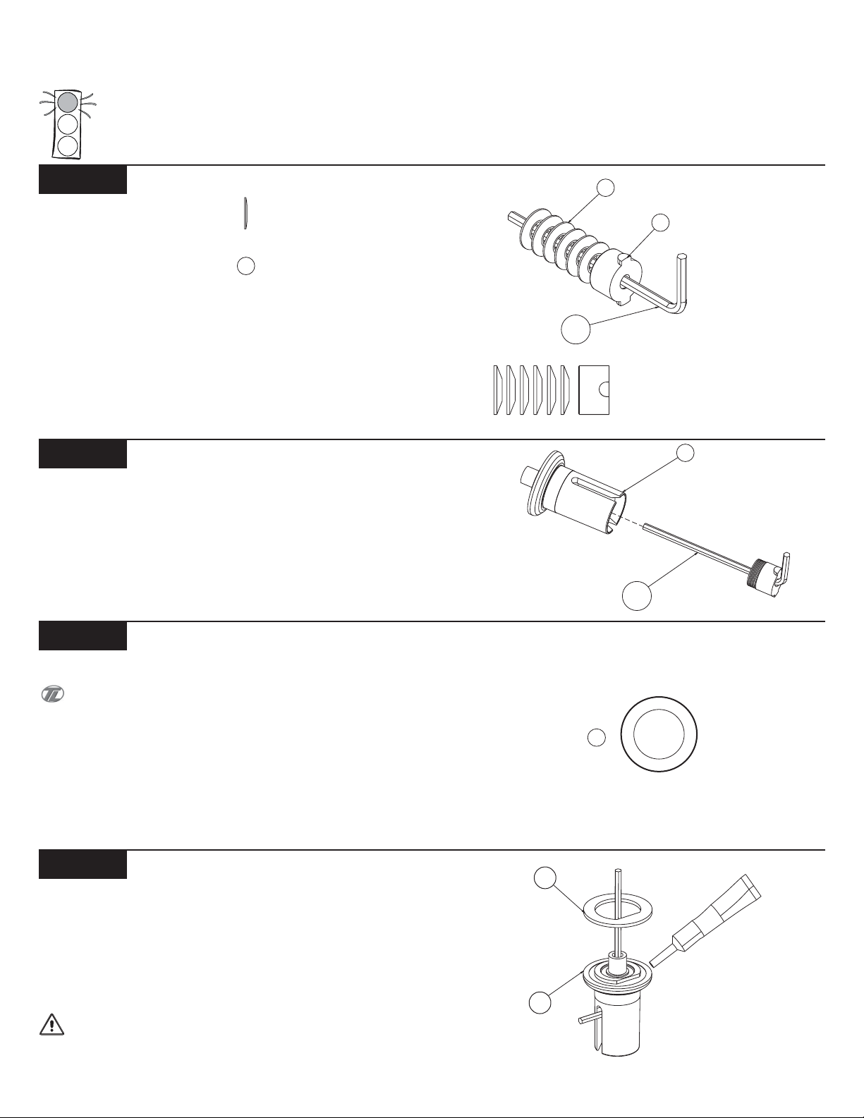
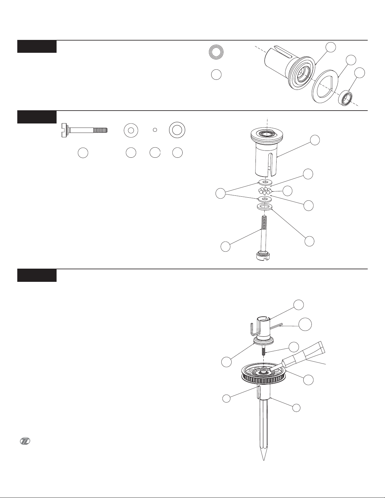
Step A-1
Diff Nut With Belleville Washers Assembly
3
q 1. Locate the 1/16" Allen wrench (159) supplied with the kit. Place
the Diff Nut (2), "T" side first, over the Allen Wrench towards the "Lend."
q 2. Stack the six 1/8" Belleville Washers (3) over the Wrench, up
against the Diff Nut. The Washers should all point the same direction
and open away from the Diff Nut as shown in Figure 2B.
Step A-2
Diff Nut to Male Outdrive Assembly
q 1. Insert all of the parts that are stacked on the Wrench (159) into
the Male Plastic Outdrive (7) (the one with the post). Line up the tabs
on the Diff Nut (2) with the slots in the Outdrive. Press the parts all
the way into the Outdrive.
3
2
Figure 1A
159
Figure 1B
7
Figure 2
159
Step A-3
Front Spool Option
You have the option of building your XXX-S with either a front
Differential, or a front Spool (Solid Axle). Refer to the "Tips from The
Team" section in the back of this manual to help you decide which is
best for you. If you decide to build your XXX-S with the front Spool,
refer to the addendum included in the bag with the front Spool Pads
(1). Otherwise continue on to Step A-4.
Step A-4
Diff Drive Ring to Male Outdrive
q 1. Apply a small amount of Clear Diff Grease (8) to the outside
ring of the Male Plastic Outdrive (7). Attach a Diff Drive Ring (10) to
the Outdrive by lining up the flat section of the Ring with the flat
section on the Outdrive.
*NOTE: Only a small amount of Grease is needed. It is only
used to hold the Drive Ring in place.
IMPORTANT NOTE: Do not glue the Drive Rings to the
Outdrive/ Diff Halves. Doing so may not allow the Rings to mount
flat.
z
z
z
z
z
z
z
z
z
z
z
z
z
z
z
z
z
z
z
z
z
z
z
z
z
z
z
z
z
z
z
z
z
z
z
z
z
z
z
z
z
z
z
z
z
z
z
z
z
z
z
z
z
z
z
z
z
z
z
z
z
z
z
z
z
z
z
z
z
z
z
z
z
z
z
z
z
z
z
z
z
z
z
z
z
z
z
z
z
z
z
z
z
z
z
z
z
z
z
z
z
z
z
z
z
z
z
z
z
z
z
z
z
z
z
z
z
z
z
z
z
z
z
z
z
z
z
z
z
z
1
z
z
z
z
z
z
z
z
z
z
z
z
z
z
z
z
z
z
z
z
z
z
z
z
z
z
z
z
z
z
z
z
z
z
z
z
z
z
z
z
z
z
z
z
z
z
z
z
z
z
z
z
z
z
z
z
z
z
z
z
z
z
z
z
z
z
z
z
z
z
z
z
z
z
z
z
z
z
z
z
z
z
z
z
z
z
z
z
z
z
z
z
z
z
z
z
z
z
z
z
z
z
z
z
z
z
z
z
z
z
z
z
z
z
z
z
z
z
z
z
z
z
z
z
z
z
z
z
z
z
z
z
z
z
z
z
z
z
z
z
z
z
z
z
z
z
z
z
z
z
z
z
z
z
z
z
z
z
z
z
z
z
z
z
z
z
z
z
z
z
z
z
z
z
z
z
z
z
z
z
z
z
z
z
z
z
z
z
z
z
z
z
z
z
z
z
z
z
z
z
z
z
z
z
z
z
z
z
z
z
z
z
z
z
z
z
z
z
z
z
z
z
z
z
z
z
z
z
z
z
z
z
z
z
z
Figure 4
1
BAG A (Continued)
DIFF ONLY
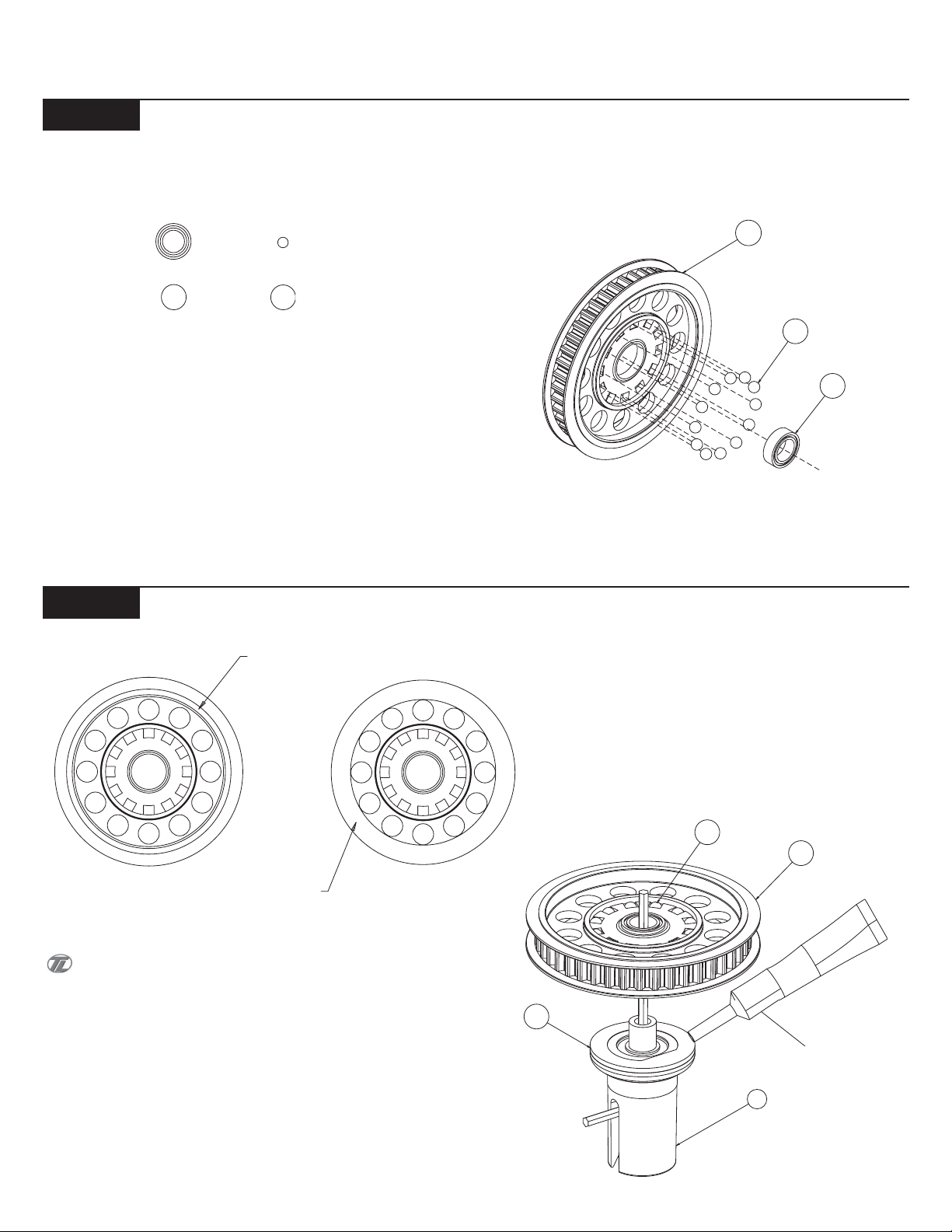
Step A-5
Diff Pulley Assembly
13
14
q 1. Insert a 5mm x 8mm Bearing (13) into the center of the 42T Diff
Pulley (11).
*NOTE: Do not use any of the large diameter Diff Balls (14)
(referring to the front assembly only!) when building the optional
front Spool.
q 2. Press a 3/32" Diff Ball (14) into each of the small holes in the
Diff Pulley as indicated in Figure 5.
11
14
13
Figure 5
Step A-6
Rerer to the "Tips From the Team" section in the back of this
manual to help you decide if you should build your XXX-S with the
Optional Over/Under-drive using the Pulleys Identified above.
*NOTE: Do not use any Clear Diff Grease (8) (referring to the front
assembly only!) when building the optional front Spool.
Diff Pulley to Male Outdrive Assembly
42T PULLEY
"w/ FLANGE"
41T PULLEY
"w/o FLANGE"
(BAG H)
q 1. Apply a heavy coat of Clear Diff Grease (8) to the exposed side
of the Diff Ring (10) that is already attached to the Male Outdrive (7).
q 2. Carefully place the Diff Pulley (11) over the post on the Outdrive
so that the Diff Balls (14) and Diff Pulley rest against the greased
Drive Ring. Leave the assembly with the 1/16" Allen wrench (159)
standing as shown in Figure 6.
10
14
Figure 6
11
CLEAR DIFF
GREASE (8)
DIFF ONLY
7
2
BAG A (Continued)
13
10
15
PENCIL
2
7
11
10
15
16
CLEAR DIFF
GREASE (8)
DIFF ONLY
DIFF ONLY
159
Step A-7
Diff Drive Ring to Female Outdrive
q 1. Press a 5mm x 8mm Bearing (13) into the center area of the
Female Plastic Outdrive (15) as indicated. The edge of the Bearing
should be flush with the front of the Outdrive.
q 2. Apply a small amount of Clear Diff Grease (8) to the outer ring
of the Outdrive. Install the second Drive Ring (10), again aligning the
flat sections of the Outdrive and the Drive Ring.
Step A-8
Thrust Bearing Assembly and Install
16
18
19
17
q 1. Place the Foam Thrust Bearing Seal (17) over the shoulder of
the Diff Adjusting Screw (16).
q 2. Place one of the 1/8" x 5/16" Thrust Bearing Washers (18) over
the Diff Screw.
q 3. Using the Red MIP Grease (78), apply a fairly heavy coat of
Grease to the Thrust Washer and position eight of the 5/64" Thrust
Balls (19) in a circular pattern around the Diff Screw. Apply another
coat of Red MIP Grease over the Thrust Balls and place the second
Thrust Bearing Washer over the Screw, against the Thrust Balls.
q 4. Insert the Diff Screw into the Female Outdrive. Pull the threaded
end of the Screw until the Thrust assembly rests against the inside of
the Outdrive.
13
Figure 8
18
16
Figure 7
78
MIP RED
19
GREASE (78)
78
17
15
Step A-9
Final Differential Assembly
q 1. Carefully remove the Allen Wrench (159) from the Male
Outdrive (7) and replace it with a pen or pencil. Place the Allen Wrench
in the slot of the Female Outdrive (15) containing the Diff Screw (16).
The pen will be used to hold the Diff Nut (2) and Belleville Washers
(3) in the bottom side.
q 2. Apply a fairly heavy coat of Clear Grease (8) to the exposed
side of the Diff Balls (14) in the Diff Pulley (11) on the Male Outdrive
(7).
q 3. While holding the Female Outdrive with Allen Wrench inserted,
carefully assemble it to the Male half.
q 4. Make sure that the slot in the Diff Screw is lined up with the
slot in the Female half. While holding the Male Outdrive half, slowly
turn the Female Outdrive until the threads of the Diff Screw engage
on the threads of the Diff Nut. Remove the pencil from the male half
and thread the two Outdrives together until the Screw just starts to
snug up.
q 5. Tighten the Diff until the Pulley cannot be turned while both of
the Outdrives are being held firmly. Final diff adjustment should be
made after completion of the XXX-S.
When tightening the Diff, tighten the Screw a little and then
"work" the Diff a little. Then tighten the Screw a little more and
"work" the Diff again. Continue this until the Diff doesn't slip. This
ensures that the parts in the Diff are properly seated. Refer to tech
tips for final adjustment. "Working" the Diff is done by rotating the
Outdrives in opposite directions.
Figure 9
3
BAG B
*NEVER PINCH THE BELT*
NEVER OVER TIGHTEN THE SCREWS IN THE CHASSIS - Team
Losi has designed interlocking features into the XXX-S chassis, when
screws are to the point of being snug the parts are held firmly in place.
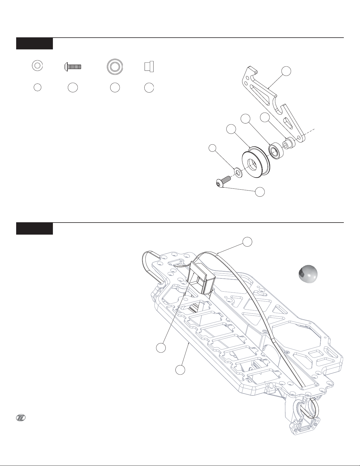
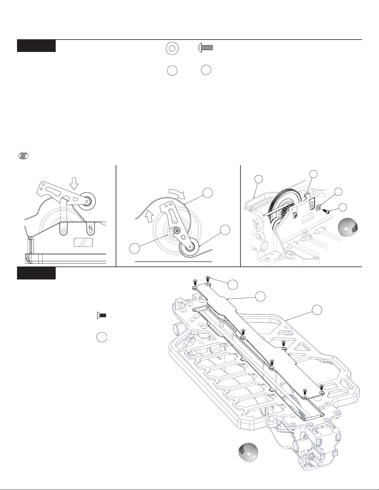
Step B-1
9
Idler Pulley to Belt Tensioner
24
25
22
q 1. Snap a 3/16" x 3/8" Bearing (25) into the right side of the Idler
Pulley (23). The Bearing will snap past the ridge in the Pulley and
stop.
q 2. Place the Idler Pulley Shaft (22) through the Idler Pulley from
the Bearing side.
q 3. Slide a #4 x .020 Washer (9) over the 4-40 x 5/16" Button Head
Screw (24).
q 4. Insert the 4-40 x 5/16" Button Head Screw through the Idler
Pulley Shaft and secure it to the Belt Tensioner Arm (21) as shown in
Figure 10.
21
25
23
9
22
24
Figure 10
Step B-2
Pinching the Belt can reduce the life of the Belt.
Belt Installation
28
*NEVER PINCH THE BELT*
q 1. Position the Chassis (27) upside-down on your work bench.
Insert the Belt (26) and pull it through both ends of the Chassis.
q 2. Pull the Belt out, just slightly, through the bottom of the Chas-
sis and insert the Steering Tunnel (28), tall end forward, into the slot
in the front of the Chassis. Press into position as indicated in Figure
11.
The Steering Tunnel should now be located in between the
Belt, with the Belt still slightly hanging out of both ends of the car.
26
27
Figure 11
4
BAG B (Continued)
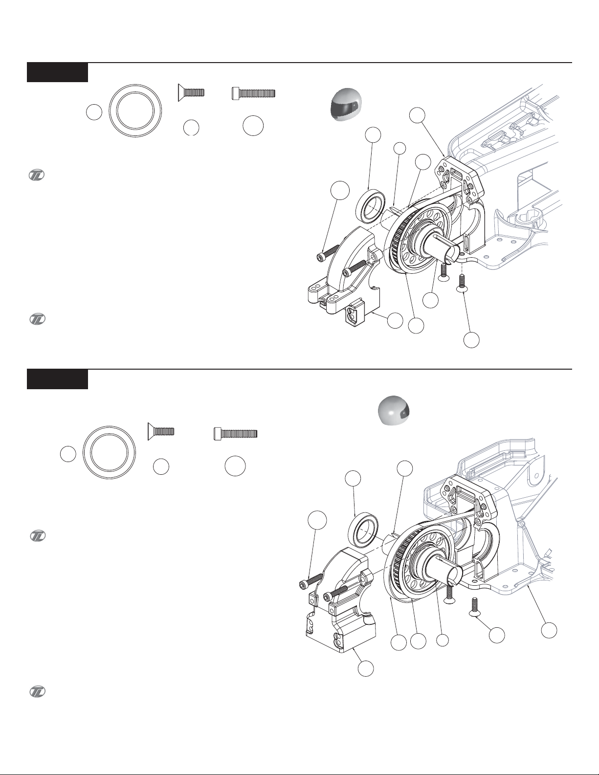
Step B-3
Front Diff Install
20
31
122
q 1. Slide one 1/2" x 3/4" Bearing (20) over each of the Outdrive
Cups (7),(15).
The Diff adjustment Screw should be facing the drivers left side
of the Chassis.
q 2. Pull the Belt (26) slightly out of the front of the Chassis (27)
and install a Diff assembly into the slots as indicated in Figure 12. Pull
the slack from the Belt through the rear of the Chassis.
q 3. Secure the Diff assembly by installing the Front Diff Cover (29)
with two 4-40 x 1/2" Cap Head Screws (122) through the Diff Cover
into the two holes in the Chassis.
q 4. Flip the Chassis over and install the two 4-40 x 3/8" Flat Head
Screws (31) through the bottom of the Chassis into the Front Diff
Cover as indicated in Figure 12.
There is a short thread-cutting screw included in the wrench
bag. This screw can be used to tap threads in the holes in the main
Chassis and the bottom of the Diff Cover. Pre-tapping these holes
makes it easier to install the Screws during assembly.
122
Figure 12
20
29
27
7
26
15
11
31
Step B-4
20
Rear Diff Install
31
122
q 1. Slide one 1/2" x 3/4" Bearing (20) over each of the Outdrive
Cups (7),(15) on the remaining Differential.
Once again, the Diff Adjustment Screw should be facing the
drivers left side of the Chassis.
q 2. Spread the Belt (26) apart and install the Diff assembly into the
slots of the Chassis (27) as indicated in Figure 13. Once the Diff
assembly is in place, pull the slack up through the center of the Chassis from the top side.
q 3. Secure the Diff assembly by installing the Rear Diff Cover (32)
with two 4-40 x 1/2" Cap Head Screws (122) through the Diff Cover
into the holes in the rear of the Chassis.
q 4. Flip the Chassis over and install the two 4-40 x 3/8" Flat Head
Screws (31) through the bottom of the Chassis into the Rear Diff
Cover as indicated in Figure 13.
There is a short thread-cutting screw included in the wrench
bag. This screw can be used to tap threads in the holes in the main
Chassis and the bottom of the Diff Cover. Pre-tapping these holes
makes it easier to install the Screws during assembly.
122
20
32
15
26
7
11
Figure 13
31
27
5
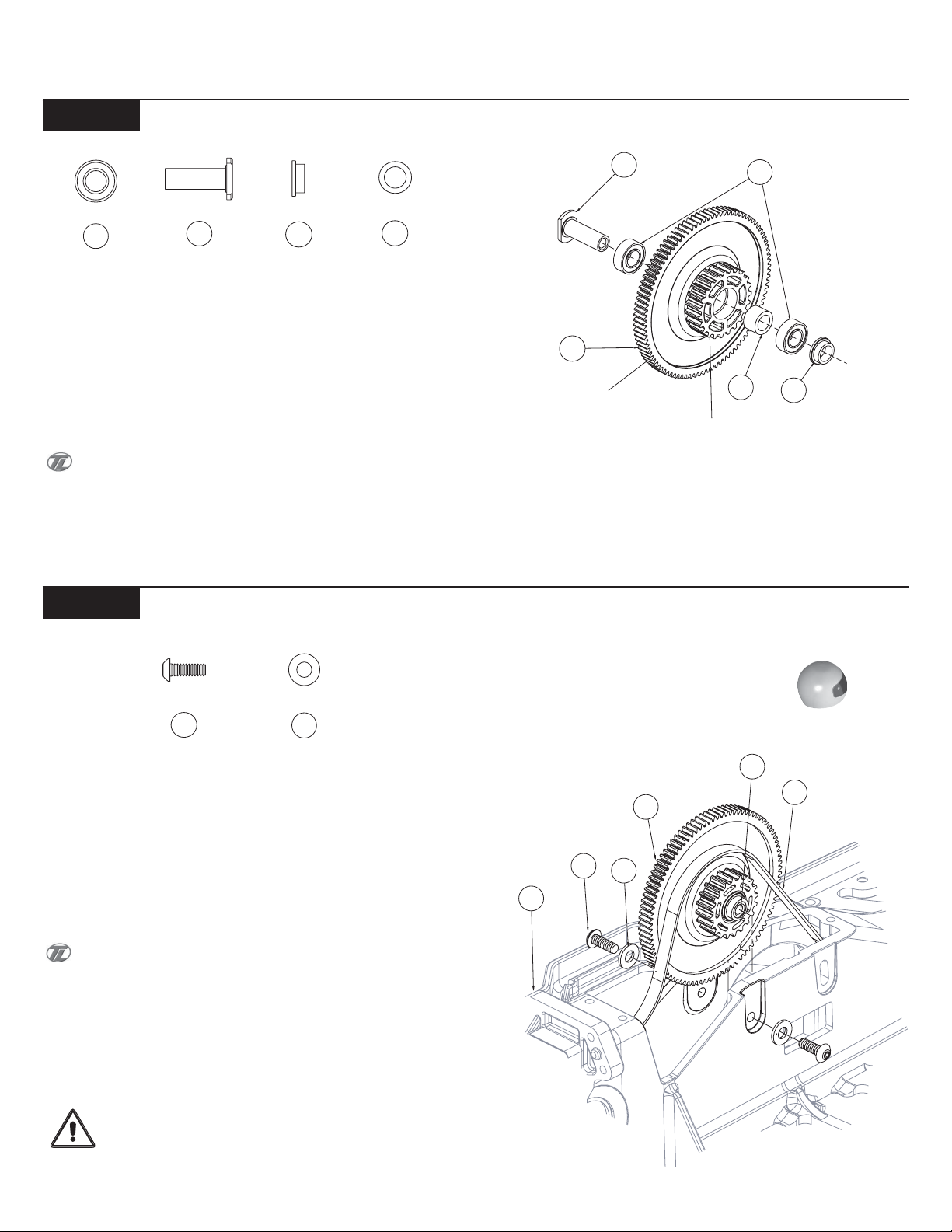
BAG B (Continued)
Step B-5
25
Top Shaft Assembly
33
34
35
q 1. Press a 3/16" x 3/8" Bearing (25) into the "Spur Gear" side of
the Drive Pulley (36). Slide the Top Shaft (33) through the Bearing in
the Drive Pulley from the Spur Gear side.
q 2. From the "Drive Gear" side of the Drive Pulley slide the Top
Shaft Spacer (35) over the Top Shaft. Place a second 3/16" x 3/8"
Bearing (25) over the Top Shaft and press the Bearing into the "Drive
Gear" side of the Drive Pulley.
If the sealed bearing has a teflon seal (colored, woven look-
ing) in it, position the seal to the outside of the drive pulley.
q 3. Slide the Belt Tensioner Bushing (34) over the Top Shaft with
the flanged side of the Tensioner Bushing towards the Drive Pulley.
36
SPUR
33
DRIVE
GEAR
Figure 14
35
25
34
Step B-6
Top Shaft Install
24
37
q 1. Holding the Drive Pulley assembly, with thumb and index fin-
ger, pull the Belt (26) up through the Chassis (27), as shown in Figure
15, and line up the Top Shaft (33) with the holes in the Chassis.
q 2. Place a #4 Hardened Washer (37) over a 4-40 x 5/16" Button
Head Screw (24) and insert it through the left side of the Chassis
threading it into the Top Shaft as indicated in Figure 15.
You may need to slightly pinch the Chassis to install the 4-40 x
5/16"Button Head Screw.
q 3. Once again, place a #4 Hardened Washer over a 4-40 x 5/16"
Button Head Screw and insert it through the Chassis and thread it
into the right side of the Top Shaft located in the Drive Pulley assembly.
Leave the right side Screw a bit loose until the Belt Tensioner Arm
is installed.
27
Figure 15
24
37
33
26
36
IMPORTANT NOTE: Never pinch the Belt as it will re-
sult in a shorter life of the belt and cause your vehicle to stop running.
6
BAG B (Continued)
21
27
37
38
Step B-7
Belt Tensioner Arm Install
37
38
q 1. Slide the Tensioner Arm assembly down over the Belt (26) and connect the slot in the Tensioner Arm (21) with the Tensioner Arm Bushing
(34) as indicated in Figure 16A.
q 2. Slowly start rotating the Tensioner Arm around the Tensioner Bushing in a clockwise direction as shown in Figure 16B. While rotating
the Tensioner Arm assembly, slightly pull upward to keep the Tensioner Arm locked and rotating on the Tensioner Bushing. The Belt must be
positioned between the Drive Pulley (36) and the Tensioner Arm.
q 3. Place a #4 Hardened Washer (37) over a 4-40 x 1/4" Button Head Screw (38).
q 4. Once you have the Belt wrapped around the Drive Pulley, and Belt Tensioner in position, as shown in Figure 16C, secure the Tensioner
assembly by threading the 4-40 x 1/4" Button Head Screw, with Washer, through the Chassis (27) into the bottom hole in the Tensioner Arm.
With the 4-40 x 1/4" Screw about one turn loose, push down on the flat part of the Tensioner and set the desired Belt tension, tighten the Screw.
The Belt should move 1/4" (6mm) to 3/8" (9.5mm) up and down for the ideal tension.
Figure 16A
Figure 16B
26
Figure 16C
36
Step B-8
Chassis Bottom Cover Install
40
q 1. Seal the drive train by placing the Bottom Chassis Cover (39)
with the flat side towards the bottom of the Chassis (27). Secure the
Bottom Chassis Cover with seven 2-56 x 1/4" Flat Head Screws (40).
23
40
39
27
Figure 17
7
BAG C
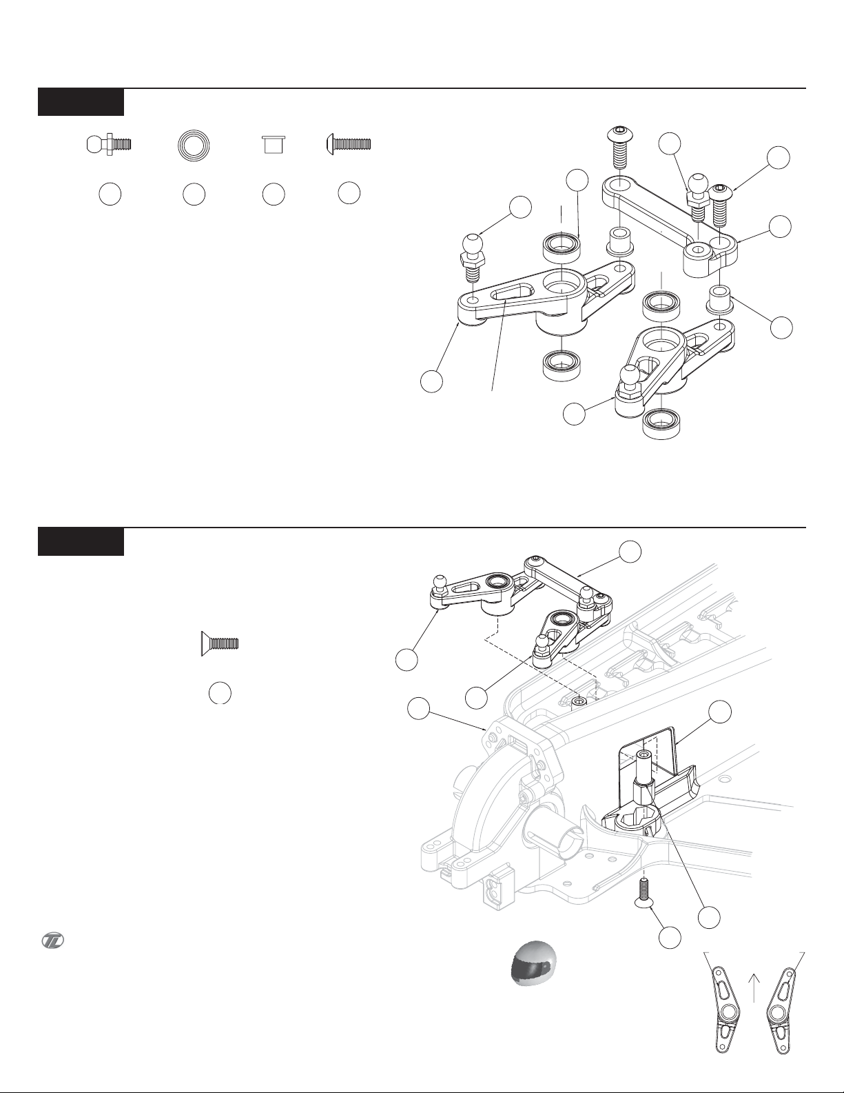
Step C-1
Steering Bellcrank Assembly
43
13
47
49
q 1. Thread a 3/16" Ballstud (43), from the top side, into each of the
Left (42) and Right (41) Bellcranks.
q 2. Insert a 5mm x 8mm Bearing (13) into the top and bottom of the
Left and Right Bellcranks.
q 3.Thread a 3/16" Ball Stud (43) into the small hole from the top
side of the Draglink (48).
q 4. Insert the 2 Carrier / Steering bushings (47), into the bottom
side of the Draglink (48) and then rest it on the top of the Left and
Right Bellcranks.
q 5. Thread a 4-40 x 3/8" Button Head Screw (49) through the Car-
rier / Steering Bushing and into each Bellcrank.
42
LARGE HOLES
FORWARD
43
49
13
43
48
47
41
Figure 18
Step C-2
Steering Bellcrank Install
42
31
q 1. Line up the Hex on the Steering Post (44) with the rear Hex area
on left side of the Chassis (27). Press the Steering Post to the bottom
of the Hex. Thread a 4-40 x 3/8" Flat Head Screw (31) through the
bottom of the Chassis and into the Steering Post.
q 2. Repeat step 1 for the right side steering post.
q 3. Slide the Steering Assembly from step C-1 through the Steer-
ing Tunnel (28) with the large holes facing forward, and then slide the
Left Bellcrank (41) over the Steering Post on the left side of the Chassis.
q 4. Sliding the Right Bellcrank (42) over the Right Steering Post
will need to be done at the same time as the Left Bellcrank.
The bellcrank should rotate freely.
27
41
48
Figure 19A
28
44
31
LARGE HOLES
Figure 19B
8
44
46
24
BAG C (Continued)
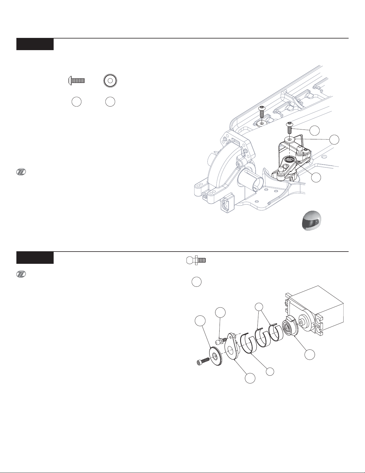
Step C-3
Steering Bellcrank Install Cont.
24
46
q 1. Place a Steering Cap (46) (flat side up) over two 4-40 x 5/16"
Button Head Screws (24).
q 2. Thread each of the Screws into the top of both the Left and
Right side Steering Posts (44) to capture the Left (41) and Right (42)
Steering Bellcranks.
The steering assembly should rotate freely. Be sure that the
screws are not too loose but, not too tight.
Figure 20
Step C-4
Servo Saver Assembly and Install
All standard servos should use only one Silver Spring and
one Gold Spring. All hi-torque & high-speed servos will use all
three Springs.
q 1. Using Table 22 (on the following page), determine which Servo
Saver Base (51) is required for your servo. If your particular servo is
not listed, try using the Arm recommended for another servo made by
the same manufacturer.
q 2. Thread a 3/16" Ball Stud (43) into the outer Servo Saver Arm
(53) from the front side as indicated in Figure 21.
q 3. Plug the servo into the radio system's receiver (not included).
Make sure that there is power to the receiver, and turn the transmitter
on followed by the receiver. Be sure that the trim settings for the
steering on your transmitter are set to the center. With the radio system still turned on, attach the Servo Arm to the output shaft so that
the Arm is vertical as shown in Figure 21.
q 4. Turn off your receiver then radio, slide one of the two "Silver"
Servo Saver Springs (4) over the Servo Arm which is connected to the
servo. Fit the second of the "Silver" Springs over the first Spring
followed by the "Gold" Spring (6). The Springs should all be pressed
against the back of the Servo Saver Base.
q 5. Press the outer Servo Arm into the Servo Saver Base. Insert
the Servo Saver Washer (54) into the Outer Servo Saver Arm. Secure
the assembly to the servo with the servo arm screw supplied with the
servo.
43
4
43
54
51
6
53
Figure 21
9
 Loading...