

Losi LOSK0800 User Manual

INTRO
INTRO
STEP I-01
Intro to the 8IGHT Manual
Welcome Team Losi 8IGHT Owner!
Thank you for selecting the 8IGHT as your new racing buggy. The 8IGHT has already distinguished itself as a top caliber racing chassis and as you will see, we have made every effort to produce a kit that is not only the most competitive but also easy to build and maintain.
The simple bag-by-bag assembly sequence and easily followed instructions and drawings combined with Team Losi’s world famous quality
fi tting parts will make building the 8IGHT a most enjoyable project.
Before you open the fi rst bag, or start assembly, please take a moment to read through the following instructions. This will familiarize
you with the various parts, assembly tips, and descriptions as well as the tools needed. Taking an extra moment before starting can save a
good deal of time and assure proper assembly.
Good luck and good racing,
Team Losi
8IGHT COMPLETED KIT SPECIFICATIONS
Overall Chassis Length: 16-1/4in (413mm) Wheelbase: 12.64-12.80in (321-325mm) *Front Track W idth: 12.13in (308mm)
Overall Length w/Tires: 19-1/4in (489mm) *Overall Height: 6-5/8in (168mm) *Rear Track W idth: 12.13in (308mm)
Note: Final kit weight will vary depending on accessories used.
*All measurements taken at ride height (32mm).
Table 1: 8IGHT Completed Kit Specifi cations.
Kit/Manual Organization:
The kit is composed of different bags marked A through H. Each
bag contains all of the parts necessary to complete a particular section of the kit. Some of these bags have sub-assembly bags within
them. It is essential that you open only one bag at a time and follow
the correct assembly sequence, otherwise you may face diffi culties in
fi nding the correct part. It is helpful to read through the instructions
for an entire bag prior to beginning assembly. Next to each of the step
numbers is a check box. At the completion of each step, place a check
in this box so that if you must stop and come back to the assembly,
you will be able to pick up where you left off.
For your convenience, an actual-size Hardware Identifi cation
Guide is included as a fold-out page at the back of this manual. Hardware that is not easily differentiable in each step is called out with
an icon which contains a small
picture of the part genre (referenced on the Hardware Identifi cation Guide), the quantity of
that part required for what is
shown in the step, and the size
or name of that part. T o check a part, hold it against the silhouette until the correct part is identifi ed. Associated with each of these parts, in
the Hardware Identifi cation Guide, is a LOSA-Number which is used
when ordering replacement parts for your 8IGHT. In some cases, extra hardware has been supplied for parts that may be easy to lose.
Components used in each step are identifi ed by their relative
LOSA-Number and the component’s name. With the exception of
a few parts, these are not referenced in the Hardware Identifi cation
Guide.
The molded parts in Team Losi kits are manufactured to de-
manding tolerances. When screws are tightened to the point of being
snug, the parts are held fi rmly in place. For this reason, it is very
important that screws not be overtightened in any of the plastic
parts.
In some steps there will be a fi lled black circle with a white
number. These indicate the specifi c order by which assembly must
occur. In cases where steps are repeated (front/rear or left/right) these
numbers may be omitted. Please note that these numbers will not call
out every sub-step required for the step’s assembly procedures, they
will only highlight the critical order required for assembly.
In each step, there are specifi c “Detail Icons” (shaped like a stop
sign) that call out critical precautions or assembly tips for the process. There is a reference key that describes the meaning of each of
the icons located on the fold-out Hardware Identifi cation Guide at
the back of this manual.
To ensure that parts are not lost during construction, it is recommended that you work over a towel or mat to prevent parts from
rolling away.
IMPORTANT SAFETY NOTES:
1. Select an area for assembly that is away from the reach of small
children. Some parts in this kit are small and can be swallowed
by children, causing choking and possible internal injury;
PLEASE USE CAUTION!
2. The shock fl uid and greases supplied should be kept out of chil-
dren’s reach. They are not intended for human consumption!
3. Exercise care when using any hand tools, sharp instruments, or
power tools during construction.
4. Carefully read all manufacturer’s warnings and cautions for any
chemicals, glues, or paints that may be used for assembly and
operating purposes.
i

INTRO
INTRO
TOOLS REQUIRED FOR ASSEMBLY
Team Losi has supplied all necessary Allen wrenches and a special wrenchs that are needed for assembly and adjustments. The following
common tools will also be required: Needle-nose pliers, regular pliers, hobby knife, scissors or other body cutting/trimming tools, and a
soldering iron may be necessary for radio installation. 3/16”, 1/4”, 5/16”, and 11/32” nut drivers are optional.
RADIO/ELECTRONICS
A suggested radio layout is provided in this manual. Your high performance R/C center should be consulted regarding specifi c questions
pertaining to radio/electrical equipment.
HARDWARE IDENTIFICATION
When in question, use the Hardware Identifi cation Guide at the back of this manual.
For screws, the prefi x number designates the thread size and number of threads per inch (i.e., 4-40 is a #4 size thread with 40 threads per
•
inch). The second number, or fraction, designates the length of the screw. For cap head and button head screws, this number refers to the
length of the threaded portion of the screw. For fl at head and set screws, this number refers to the overall length of the screw.
Bearings and bushings are referenced by the inside diameter (I.D.) x outside diameter (O.D.).
•
Shafts and pins are designated by type (Roll, Solid) and referenced by diameter x length.
•
Washers, Spacers and Shims are described by inside diameter or the screw size that will pass through the inside diameter x the thickness
•
or by their designated application (i.e., Ball Stud washer is primarily used under a Ball Stud).
Retaining Clips are sized by the shaft diameter that they attach to or by type (Body). The Hardware Icon associated with E/C-Clips only
•
designates the part genre of clips, not the actual part.
Nuts come in four types, Non-Flanged, Flanged (F), Plain, and Locking (L) (designated on the Hardware Icons). The prefi x number desig-
•
nates the thread size and number of threads per inch. The second number, or fraction, designates the size of the hex. For example, L 4-40
x 1/4” designates a Lock nut that will thread onto a 4-40 screw using a 1/4” nut driver.
Setscrews come in three types, Cup (C), Flat (F) and Oval (O) (designated on the hardware Icons). The prefi x number designates the thread
•
size and number of thread per inch. The second number, or fraction, designates the length of the threade portion of the screw.
TABLE OF CONTENTS
SECTIONS
1. INTRODUCTION...................................................i
Kit/Manual Organization ................................... i
Important Safety Notes ...................................... i
Tools Required for Assembly ............................ii
Radio/Electronics .............................................. ii
Hardware Identifi cation ....................................ii
2. Bag A: Steering Assembly ...................................1-2
3. Bag B: Front Clip ................................................3-8
4. Bag C: Center Transmission ..............................9-12
5. Bag D: Rear Clip .............................................13-18
6. Bag E: Shocks .................................................19-21
7. Bag F: Radio Tray ...........................................22-26
8. Bag G: Engine Installation .............................. 27-30
9. Bag H: Wheels, Tires, Body ............................31-34
8. Checklist Before Your First Run ........................35
9. Setup Guide ....................................................35-39
10. Blank 8IGHT Setup Sheet ...................................24
11. Hardware Identifi cation Guide ...........................25
12. Filled-out 8IGHT Kit Setup Sheet ......................26
TABLES
Table 1: 8IGHT Completed Kit Specifi cations ............ i
Table 2: Servo Installation .........................................23
T eam Losi is continually changing and improving designs; therefore, the actual part may appear slightly different than the illustrated part. Illustrations of parts and assemblies
may be slightly distorted to enhance pertinent details.
ii
BAG A
BAG A
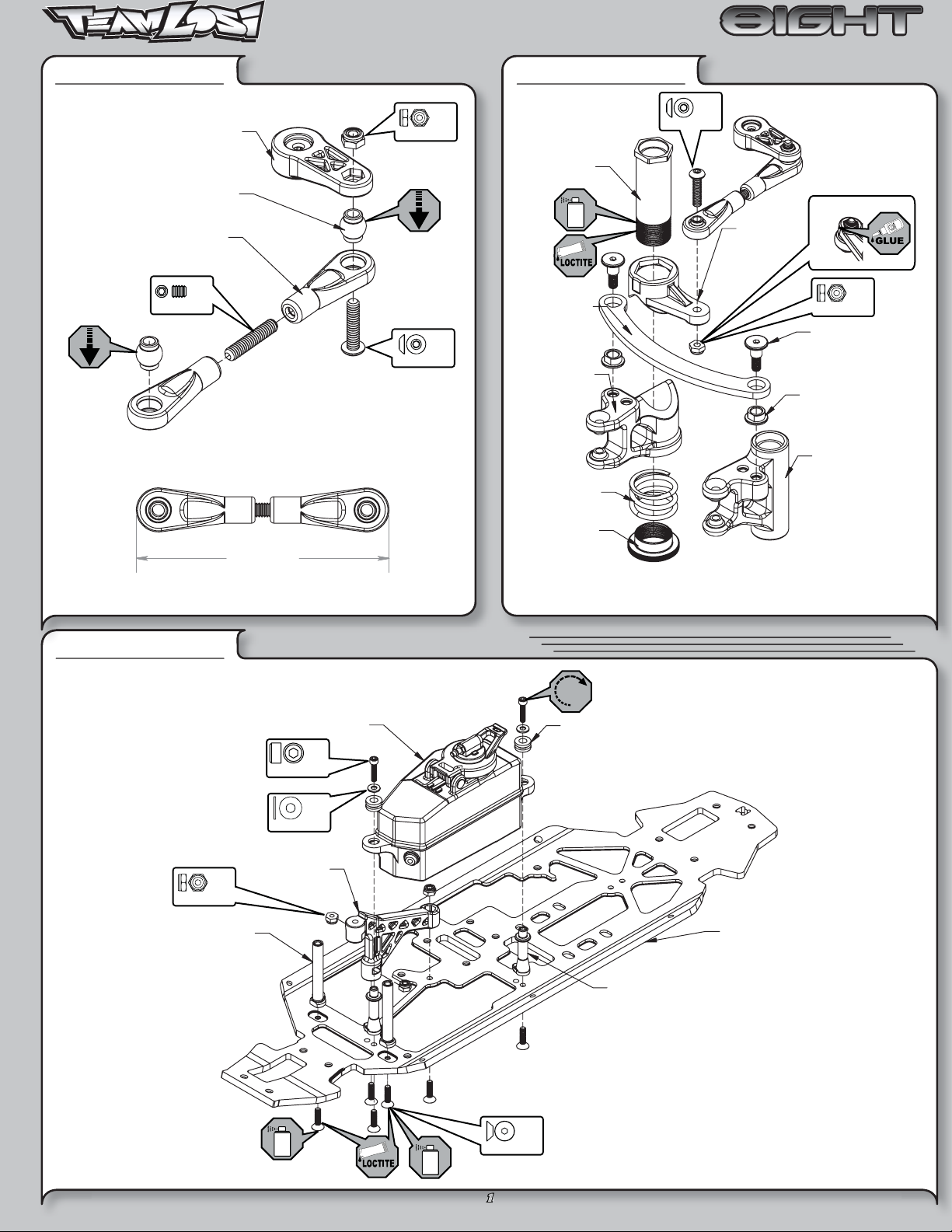
STEP A-01
A9166
Steering Servo Arm
A6043
Rod End Ball
A6043
Rod End
x 1
5-40 x 5/8”
Steering Link Assembly
L 4-40 x 3/16”
4-40 x 1/2”
x 1
x 1
STEP A-02
A4410
Servo Saver Tube
A4411
Steering Drag Link
A4409
teering Bellcrank R
A4410
Servo Saver Spring
Servo Saver Assembly
x 1
4-40 x 1/2”
A4409
Steering Arm
Maintenance Tip
x 1
L 4-40 x 3/16”
A4411
Drag Link Screw
A4411
Drag Link Bushing
A4409
Steering Bellcrank L
STEP A-03
x 3
L 5-40 x 1/4”
A4408
Steering Post
2.26"
57.40mm
Fuel Tank/Chassis Brace Assembly
A9160
Fuel Tank
x 2
4-40 x 1/2”
x 2
#4 x .030
A4413
Front Chassis Support
A4410
Servo Saver Nut
A4424
Fuel Tank Grommet
Tighten the Servo Saver
nut all the way down and
then back it off 2 1/2 turns.
A4401
Chassis
5-40 x 1/2”
1
x 6
A4424
Tank Mount
BAG A
BAG A
STEP A-04
Front Body Mount
6x10x3mm
A4413
Front Chassis Brace
A4424
x 1
5-40 x 3/8”
x 4
Steering/Top Plate Assembly
x 1
5-40 x 1/2”
x 2
5-40 x 1/2”
STEP A-05
Completed Steering Assembly
2
BAG B
BAG B
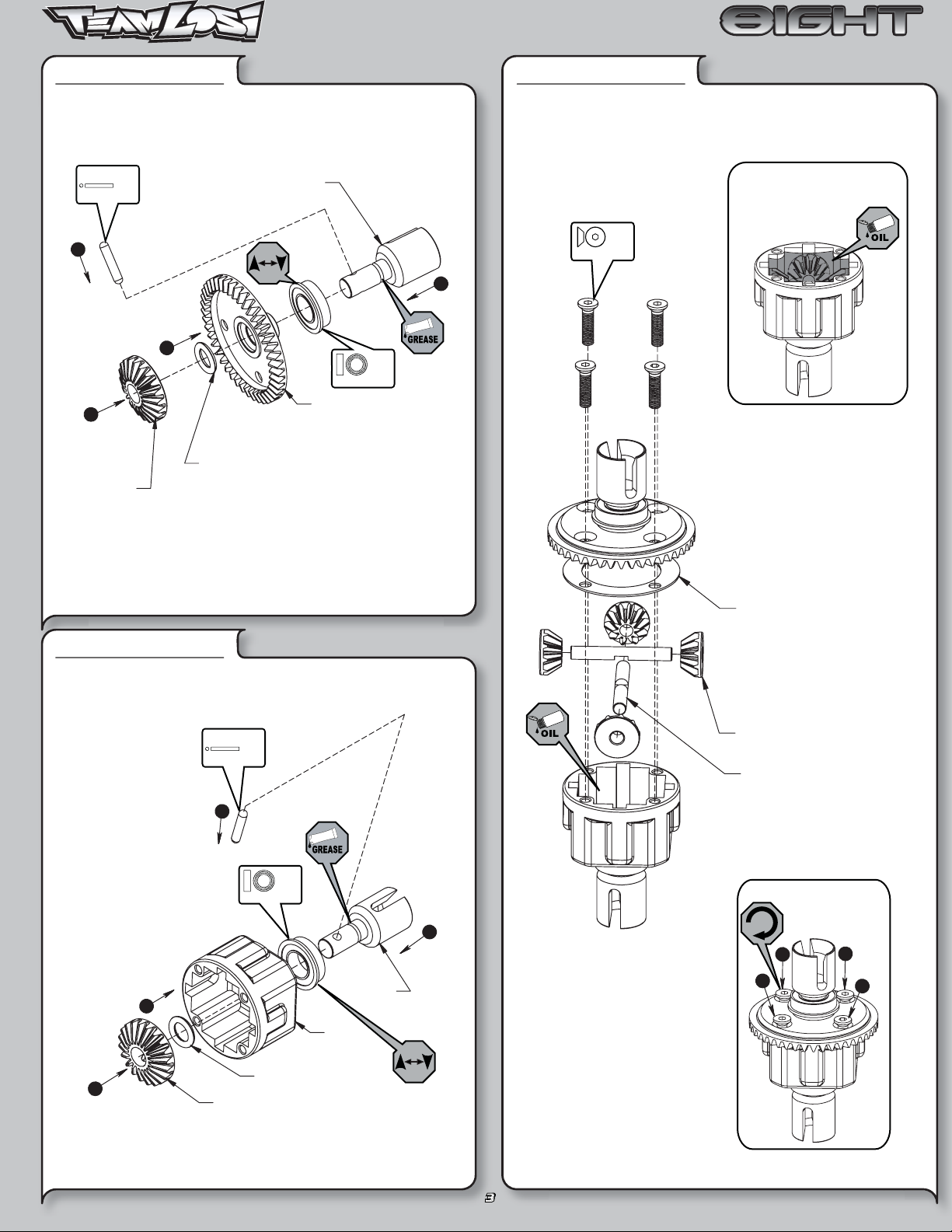
STEP B-01
Solid
x 1
2.5 x 12.80mm
3
4
A3502
Sun Gear
Ring Gear Assembly
A3504
Outdrive Cup
1
2
x 1
F 8x14x4mm
A3509
Ring Gear
A3505
O-Ring
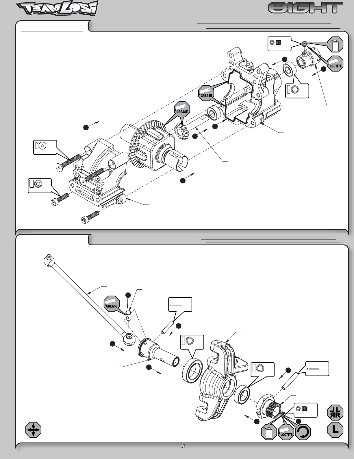
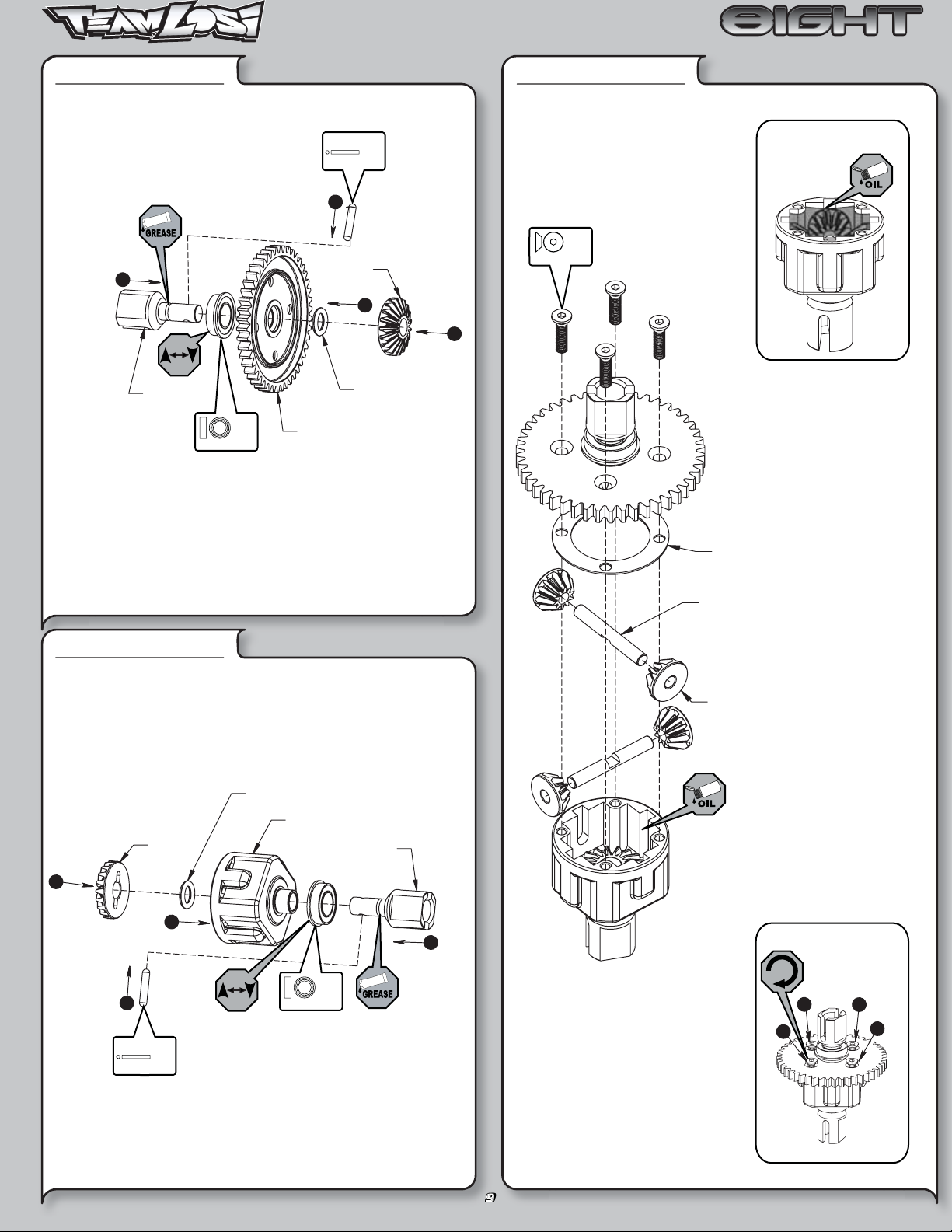
STEP B-03
3x12mm
x 4
Complete Diff Assembly
Fill with 5000wt. oil just above
the planetary gear
STEP B-02
A3505
Diff Seal
Diff Case Assembly
Solid
x 1
2.5 x 12.80mm
3
x 1
F 8x14x4mm
1
A3504
2
Outdrive Cup
A3500
Diff Housing
A3502
Planetary Gear
A3502
Planetary Gear
Axle
Tighten the diff screws
in this order
1
4
3
2
A3505
4
A3502
Sun Gear
O-ring
3
BAG B
BAG B
STEP B-04
x 2
5-40 x 7/8”
x 2
5-40 x 1/2”
Front Diff Install
6
To prevent fi ne dust from enter-
•
ing the gear box, apply a thin
bead of grease along the edge
of the case as pictured.
2
5
1
Pinion Gear, Bevel
A3508
x 1
F 8-32 x 1/8”
3
Front Bulkhead
5x11x4mm
A4427
x 2
A3514
Drive Adapter
4
STEP B-05
A4427
Front Diff Cover
Front Spindle & CV Assembly
A3521
Dogbone
2
A3522
Axle
1
A3523
CV Coupling
4
Solid
2.5 x 12.4mm
3
x 1
1/2” x 3/4”
x 1
A170 7
Left Spindle
8x14x4mm
x 1
Solid
6
x 1
3 x 17mm
A353 0
Wheel Hex
x 1
C 8-32 x 1/8”
5
4
7
BAG B
BAG B
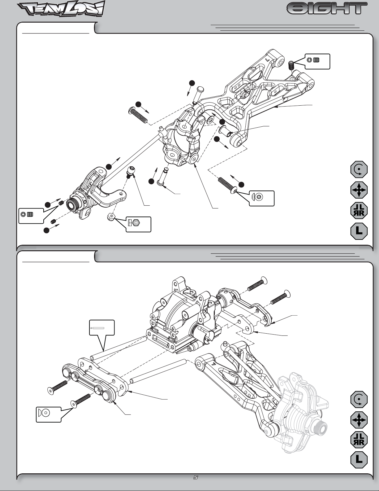
STEP B-06
x 2
C 5-40 x 3/16”
Spindle/Carrier Assembly
x 1
O 10-32 x 3/8”
2
5
4
4
1
2
A6501
Hinge Pin
3
3
5-40 x 1/4”
A6050
Steering Ball Stud
x 1
A1710
Left Spindle Carrier
5
8/32 x 3/4”
A1701
Front Arm Bushing
x 2
A1700
Left Front Arm
STEP B-07
x 4
5-40 x 3/4”
Front Suspension Arms Assembly
Solid
x 2
4mm x 65mm
A1744
Front Outer Hinge Pin Brace
A4431
Front Outer Hinge Pin Cap
Front Inner Hinge Pin Cap
A1744
Front Inner Hinge Pin Brace
A4431
5
BAG B
BAG B
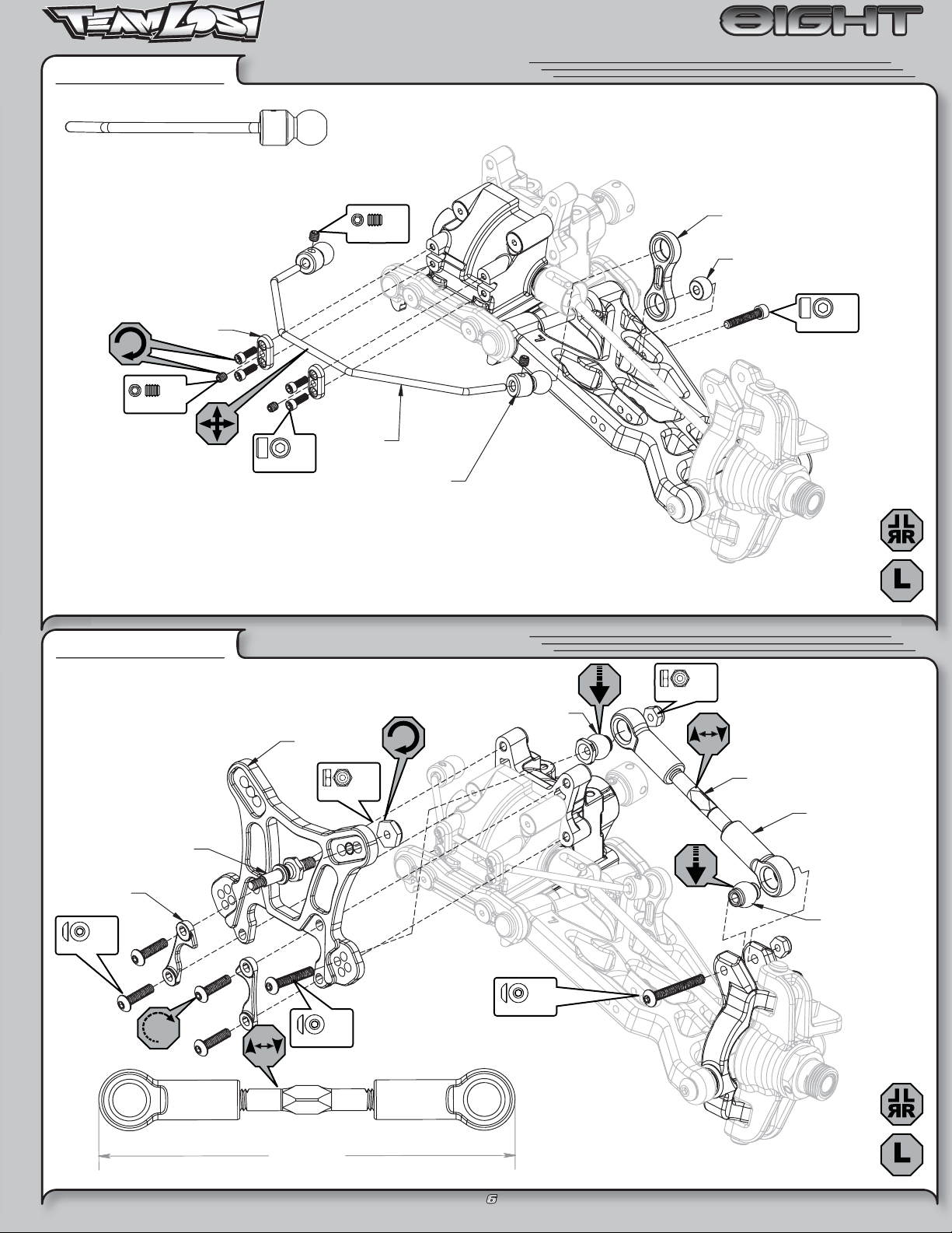
STEP B-08
Install the Swaybar Ball onto the Swaybar Wire
until the end of the wire is fl ush with the ball as
pictured above
A4426
Swaybar Mount
Cap
x 2
C 4-40 x 1/8”
Swaybar Assembly
x 4
2-56 x 1/4”
C 5-40 x 1/8”
A1750
Front Swaybar
x 2
A1750
Swaybar Ball
A1750
Swaybar Link
A1750
Swaybar Ball, Arm
x 2
4-40 x 5/8”
STEP B-09
Shock Stand-Off
A4426
Shock Tower
Mount Cap
x 4
5-40 x 1/2”
A5438
Tie Rod/Shock Tower Assembly
Suspension Ball, Flanged
A1715
Front Shock Tower
x 2
L 8-32 x 11/32”
x 2
5-40 x 3/4”
A6048
5-40 x 1”
x 1
x 2
L 5-40 x 1/4”
Be sure to install the assembled
Tierod onto the car with the groove
(next to the center square section)
on the driver’s left side for easier
adjustment later.
A6540
Turnbuckle, Front
A6047
Rod End
A6049
Suspension Ball
3.72"
94.50 mm
6
BAG B
BAG B
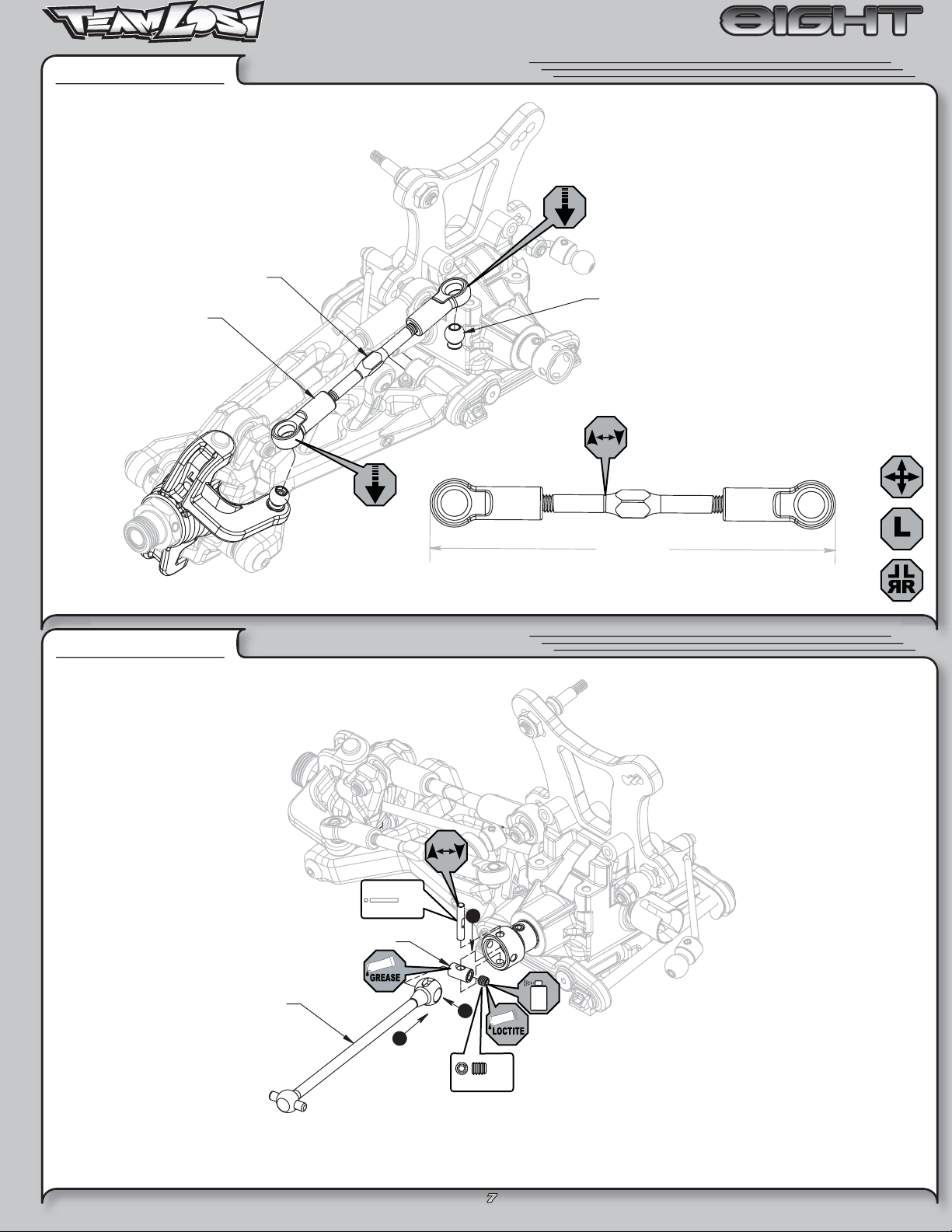
STEP B-10
Steering Turnbuckle
A6046
Steering Rod End
Front Camber Link Assembly
A6542
A6050
Steering Ball
Be sure to install the assembled
Tierod onto the car with the groove
(next to the center square section)
on the driver’s left side for easier
adjustment later.
STEP B-11
Center CV Assembly
Solid
2.5mm x 14mm
A3526
CV Coupling, Center
3.62"
92.00mm
x 1
3
A3526
Driveshaft, Center
1
2
x 1
F 5-40 x 1/8”
7

e
BAG B
BAG B
STEP B-12
Front Clip Assembly
A4422
Front Bumper
x 2
5-40 x 3/4”
4
1
5-40 x 3/4”
2
8-32 x 1/2”
x 2
x 4
A4426
Front Bulkhead Spac
3
STEP B-13
Completed Front Assembly
8
BAG C
BAG C
STEP C-01
1
A3506
Center Outdrive
x 1
F 8x14x4mm
Ring Gear Assembly
Solid
x 1
2.5 x 12.80mm
3
A3502
Sun Gear
2
A3505
O-ring
A3516
Spur Gear
STEP C-03
x 4
3x12mm
4
Complete Diff Assembly
Fill with 7000wt.
oil just above the
planetary gear
STEP C-02
4
A3502
Sun Gear
3
Solid
x 1
2.5 x 12.80mm
A3505
Diff Seal
A3502
Planetary Gear Axle
Diff Case Assembly
A3502
Planetary Gear
A3505
O-ring
A3500
Diff Housing
A3506
Center Outdrive
2
1
x 1
F 8x14x4mm
Tighten the diff screws
in this order
1
3
4
2
9
BAG C
BAG C
STEP C-04
(.5mm)(.020)
2
A3544
Brake Cam Bushing
Center Top Brace Assembly
x 1
A4415
Top Brace,
Center Diff
5mm E-Clip
1
1
A3544
Rear Brake Cam
5-40 x 1/8”
A3544
Front Brake Cam
Brake Wire
A9166
x 2
STEP C-05
Throttle Rod End
A9166
Throttle Return Spring
A9166
Threaded Servo Rod
A9166
Throttle Servo Arm
A9166
Throttle Actuator
A9166
Brake Lever Collar
A9166
A9166
Rear Brake Rod
2-56 x 1/4”
Linkage Assembly
A9166
Front Brake Actuator
A9166
Threaded Servo Rod
x 1
A9166
Rear Brake Actuator
A9166
Adjuster Collar
x 1
2-56 x 1/2”
x 2
.250x.094x020
x 3
C 4-40 x 1/8”
(7mm)
(.2760in)
STEP C-06
C 4-40 x 1/8”
x 2
.250x.094x.020
A9315
Fuel Line
Assemble both Front and
Rear Brake Lever Collars
2.80mm (.11”) from the
end of the Brake Rod.
x 2
2
Linkage Assembly
A9166
Brake Lever
Collar
A9166
Brake Bushing
(9mm)
(.3545in)
Cut two pieces
of fuel tubing
to size pictured
STEP C-07
Air Filter Guard
A4422
Tank Guard
A4422
Air Filter Mount & Guard
A9150
Air Filter Mount
x 5
5-40 x 3/8”
10
BAG C
BAG C
STEP C-08
Brake Shoulder Screw
Rear Brake Pad
A3541
A3541
Brake Caliper Assembly
A4415
Rear Center Diff Mount
A3541
Front Brake Pad
A4415
Front Center Diff Mount
0.230"
5.80mm
STEP C-09
Center Diff/Brake Rotor Assembly
4
x 4
5-40 x 3/8”
A3540
Rear Brake Disk
3
3
2
1
A4415
Bearing Insert
A3540
Front Brake Disk
1
11
 Loading...