

Page 1
Convert your Losi Micro Vehicle
from Brushed to Brushless power
Before we begin the conversion, let’s make sure we have all the components you will
need.
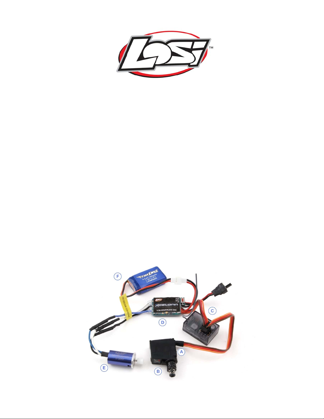
Parts Required:
A – You will need a NEW servo to replace the stock servo. We recommend the JR
SM22 servo since it replaces the stock version easily.
B – This is a servo saver for the JR SM22 servo. Part number – LOSB0820
C – The receiver chosen is the Spektrum™ Micro Receiver. Part Number – SR3500
Note: You will need a Spektrum Transmitter or one with a Spektrum Module.
D – The Electronic Speed Control (ESC) 36
E - Shown in the figure below is the brushless motor. There are two different motors
available:
LOSB9544 36
LOSB9545 36
F – Optional LiPo battery. Part number LOSB0862 w/charger and LOSB0863 w/o charger
Note: Due to the Brushless Systems operation and performance, some NiMH
battery packs may not perform under the potential loads.
th
Brushless Motor 8750Kv Also packaged with the ESC in LOSB9594
th
Brushless Motor 10200Kv
th
ESC LOSB9530 and in LOSB9594
® sport
Conversion of Brushed Micro Vehicle to Brushless page 1 of 14
Page 2
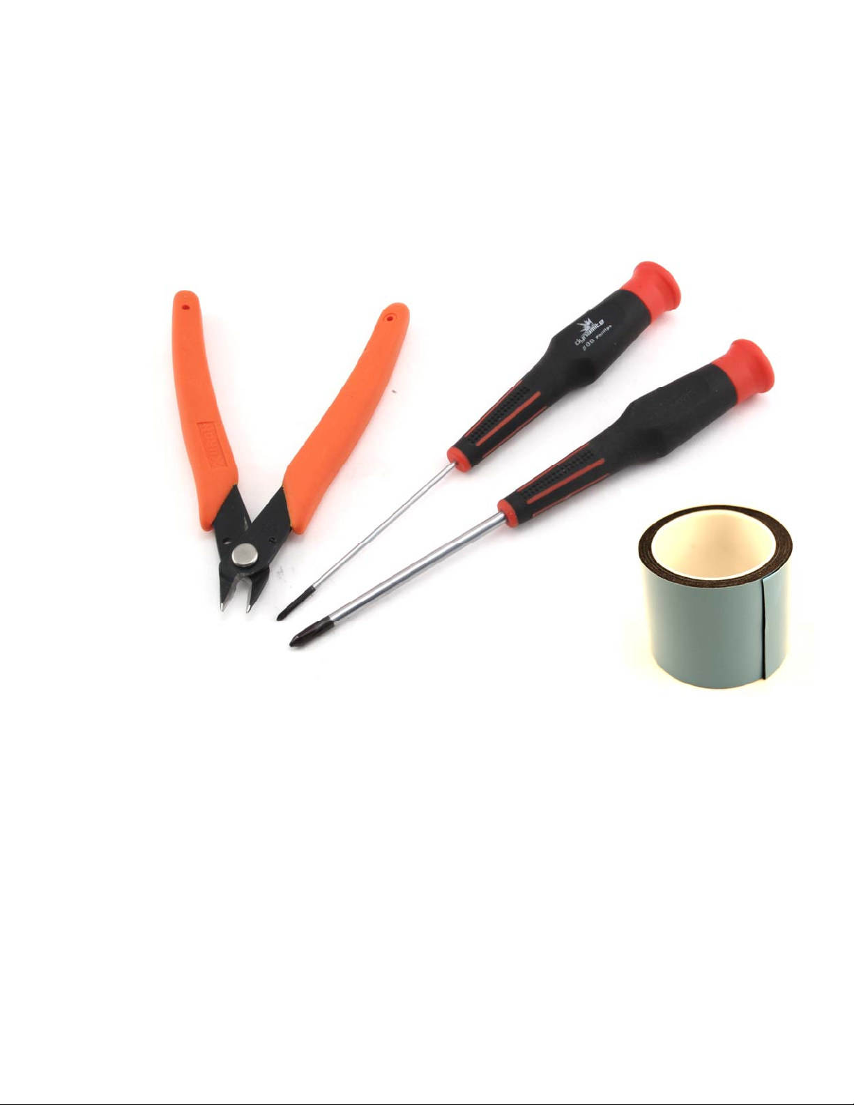
Tools Required:
The following should be available during the conversion:
• Very small Phillips screwdriver similar to the Dynamite DYN2826.
• Medium Phillips screwdriver similar to the Dynamite DYN2828.
• A pair of side cutters used to trim the servo mounts.
• Double-sided servo tape.
Conversion of Brushed Micro Vehicle to Brushless page 2 of 14
Page 3
Let’s start the conversion:
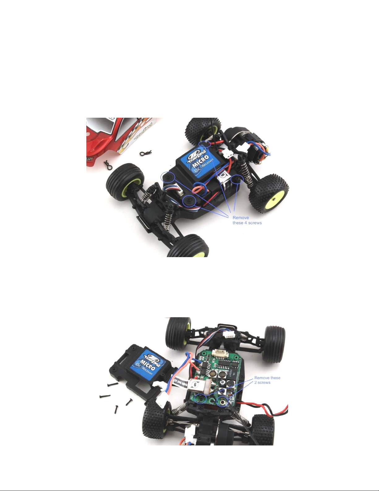
Step 1.
Remove the two body clips holding the body on, and remove the body.
Disconnect the Battery
Now remove the four (4) screws that are holding the original Receiver /ESC cover in place.
The location of the screws is noted by the circles in the figure below.
Step 2.
Disconnect the Servo lead (white plug at the top of figure below).
Remove the two (2) screws securing the actual Receiver/ESC. Shown in the circles.
Conversion of Brushed Micro Vehicle to Brushless page 3 of 14
Page 4
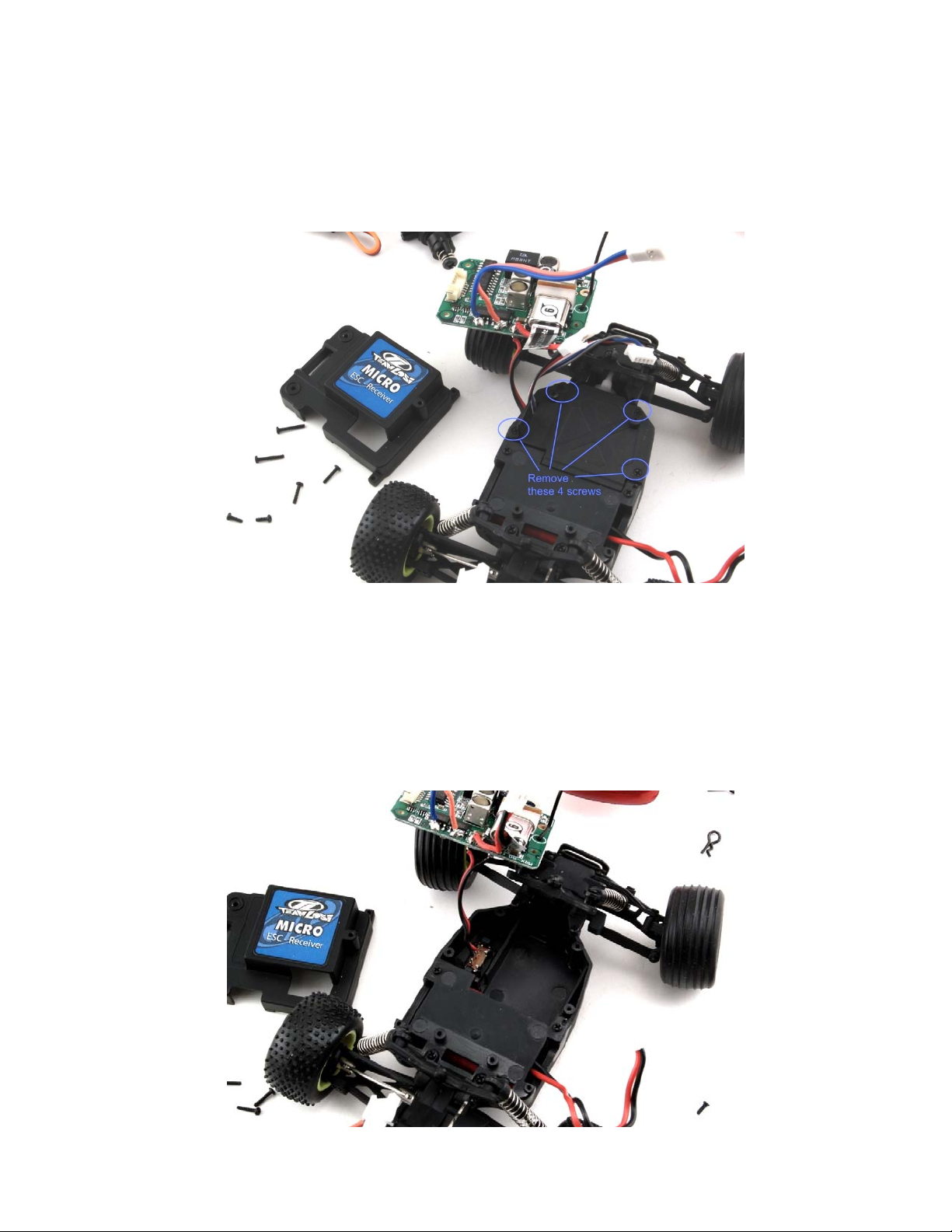
Step 3.
Lift and rotate this circuit board resting it on the left front tire as in the figure below.
Remove the four (4) screws holding the Servo cover in place. Shown in the circles.
Step 4.
With the servo cover removed, we can remove the servo by simply lifting it up and out.
Then we can remove the original ON/OFF sw itch. There are two plastic pins holding the
switch in place. Using the small Phillips screwdriver, gently push the pin/clip away from
the switch while pushing upward on the switch from the bottom of the chassis.
Conversion of Brushed Micro Vehicle to Brushless page 4 of 14
Page 5
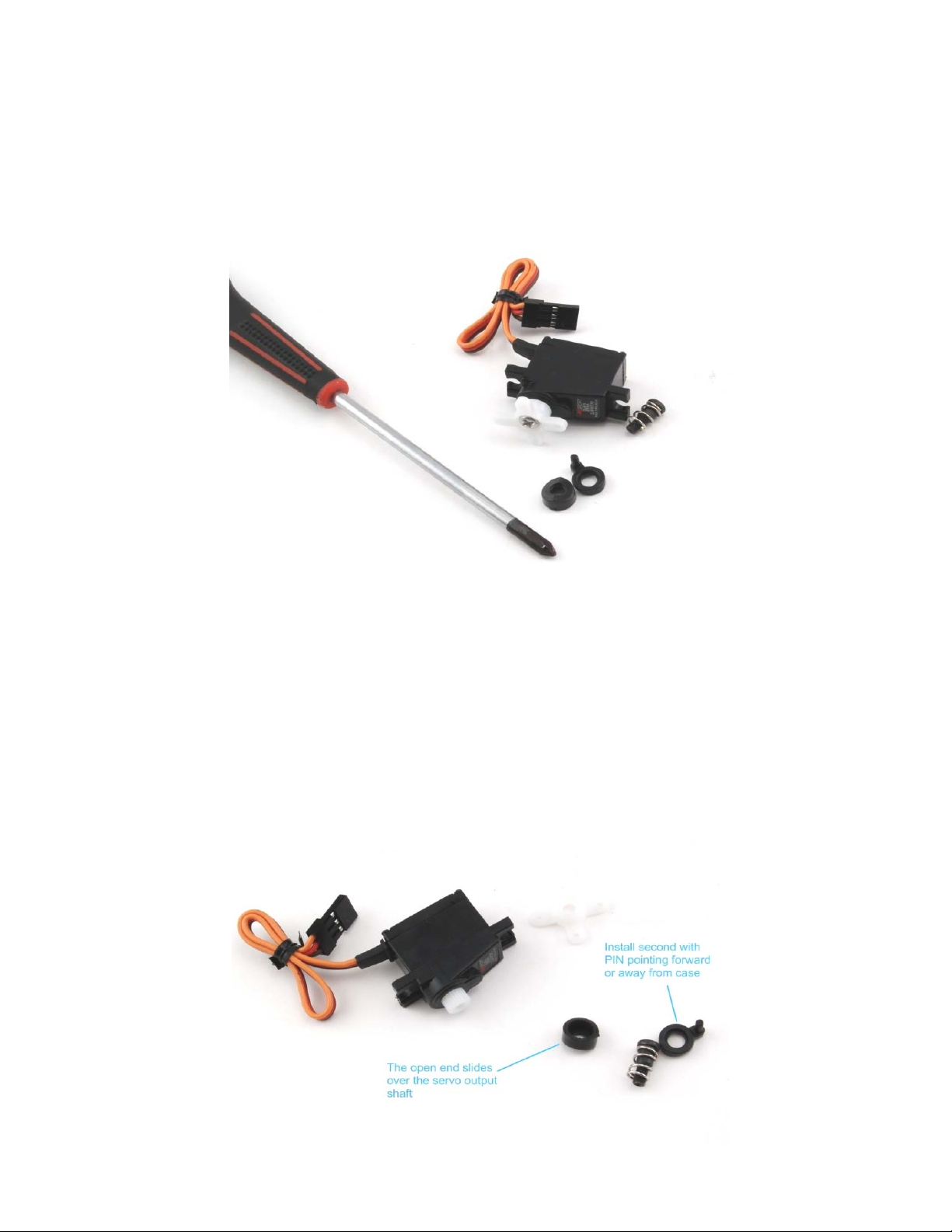
Step 5.
Installation of the servo saver
Using the larger Phillips screwdriver remove the white plastic servo horn.
Step 6.
Installation of the servo saver.
First, put the small round piece that is splined on the servo, then the piece with the point.
Slowly screw in the servo saver screw with the spring on it. Be careful to align and screw
it in straight.
Note: Be careful while screwing in this screw to not over-tighten and damage the servo
gears.
Conversion of Brushed Micro Vehicle to Brushless page 5 of 14
Page 6

Servo with saver installed should look like the figure below.
Step 8.
The original servo is on the lower right and the new JR SM22 with servo saver installed is
in the upper left of the figure below.
Conversion of Brushed Micro Vehicle to Brushless page 6 of 14
Page 7

Using the side cutters, we need to carefully remove the normal servo mounting ears.
Suggestion: Do not attempt to cut the entire ear off in one cut. The servo case is a hard
plastic material, being hard it is also brittle and may break or remove more than the
mounting ear we want to remove.
With the mounting ears now cut-off the new JR SM22 servo is ready to drop in the Micro-T
chassis.
Conversion of Brushed Micro Vehicle to Brushless page 7 of 14
Page 8

Step 9.
The servo should fit right in like the figure below.
You will most likely need to get back into this area of the vehicle to adjust the
servo saver after the electronics are installed.
Note: The PIN of the servo saver must be positioned into the small slot on the steering
link, or after assembly, the car will not properly steer.
Reinstall the servo cover now. Using the four (4) screws removed in step #4.
Conversion of Brushed Micro Vehicle to Brushless page 8 of 14
Page 9

Step 10.
In the figure below you will notice light colored “L” shapes. The receiver will be mounted
just behind and centered with those markings. Notice the raised ridge for reference.
Using double sided servo tape, cut a small piece that covers the width and long side of the
receiver. Locate the servo tape just to the rear of the ridge. We put the two silver L
shapes for reference, on the chassis to highlight and show you the location for the
receiver.
Conversion of Brushed Micro Vehicle to Brushless page 9 of 14
Page 10

The receiver has been installed.
Note: The BINDING plug location, all the PINS are pointing towards the front.
Step 11.
We are now ready to mount the ESC just in front of the receiver. Notice the “square” in
light color. Cut the servo tape twice as long so you can double up before use.
Note: We will most likely remove this in the last step to center the servo. You may want
to do that now and jump to Step 15 and then returning to Step 11.
Conversion of Brushed Micro Vehicle to Brushless page 10 of 14
Page 11

Different view with the ESC mounted on the servo tape.
Note: The steering servo and ESC have been plugged into the receiver below.
Step 12.
Now we will install the Brushless motor. First, remove the three (3) screws holding the
gear cover on.
There are two (2) screws holding the brushed “stock” motor in place. Remove these two
(2) screws.
Below the stock motor is on the right. Using the backside of the side cutters carefully
push the pinion away from the motor. The pinion is made of plastic and will come off
without much trouble.
Note: The car originally comes with three (3) pinions. The one installed on the motor is
an 11 tooth, and then two (2) more came in a plastic bag, a 10 and 12 tooth.
The 11T pinion works very good but for more speed install the 12T pinion.
Conversion of Brushed Micro Vehicle to Brushless page 11 of 14
Page 12

Select the 11T pinion to begin with and gently press the pinion on the brushless motor
(shoulder away from the motor). Using the same two (2) screws, install the brushless
motor. To mesh the gears with the 11T pinion, press the motor towards the spur gear
and snug up the bottom screw (not tight). There should be a slight bit of movement
between the two gears when you “rock” the spur gear back and fourth. If there is no slop
then gently move the motor slightly away, and if it was too loose then move the motor
forward. When set properly, the wheels can be spun forward freely and with little noise.
Make certain to tighten both motor screws and replace the gear cover before running.
Connect the motor leads (Blue-to-Blue, White-to-White, Black-to-Black)
Conversion of Brushed Micro Vehicle to Brushless page 12 of 14
Page 13

Step 13.
The Micro-T brushless conversion is near completion and should look similar to the figures
below.
Notice the switch is still hanging freely. We suggest you secure it in a convenient location
for your use. Putting it on top of the ESC over the motor leads is a favorite location.
Step 14.
Final setup:
With the battery having some charge we need to BIND the Spektrum receiver to the
transmitter. Please refer to your transmitter’s reference / setup manual.
Next, we need to check the steering servo centering.
Conversion of Brushed Micro Vehicle to Brushless page 13 of 14
Page 14

Step 15.
Servo Centering:
To check the servo centering make sure your battery is charged. Then turn on the
transmitter and the ESC. To setup the ESC refer to the instructions supplied with it. The
servo should be powered and functioning. Check your transmitter by first turning Right or
Left. Does the steering move in the correct direction for the steering input? If not you
should reverse the servo operation on the transmitter. (See your transmitter instructions.)
1. With the radio and servo still on, and with the transmitter put aside, are the
wheels pointed straight? If not adjust the sub-trim on your transmitter. If by
using the sub trim you can set the wheels to go straight, you can proceed with
Step 16.
2. Note the direction the steering is off to the Right or Left.
3. Adjust the sub-trim back to neutral (zero position) or no sub-trim on transmitter.
4. You will need to turn off the power switch, remove the ESC and servo cover, which
is secured by four (4) screws.
5. Disconnect the servo from the receiver and lift it out of the vehicle.
6. Remembering the direction (Right or Left) the servo was off, carefully remove the
screw holding the servo saver and rotate the servo saver in the direction (right or
left) needed to correct the centering.
Note: you may want to carefully reconnect the servo to the receiver, turn on your
transmitter and ESC to determine if you have moved the servo saver enough.
7. Once you have the servo saver re-centered install the servo back into the vehicle.
Refer to Step 9 above.
8. Install the servo cover with the four (4) screws.
9. Mount the ESC with servo tape. Refer to Step 11 above.
10. The vehicle should be back together now. Turn the transmitter on and then the
ESC. Using the sub-trim adjustment, you should no w be able to straighten the
wheels out. If not repeat the above steps beginning at number 4 in this section.
Step 16.
Set-up the ESC:
Follow the instructions supplied with the ESC.
You are now finished with the conversion – congratulations!
Conversion of Brushed Micro Vehicle to Brushless page 14 of 14
 Loading...