

Page 1

Operation Manual
Bedienungsanleitung
Guide de mise en oeuvre
Manuale di istruzioni
Not responsible for errors.
Losi, a Division of Horizon Hobby, Inc.
Stronghold Motorsports, Maxxis Tires, Lamb Energy, Simpson, Pro Am
Racing, Lucas Oil Products Inc., Fiberwerx Inc., K & N, Multi Mechanical
Inc., VP Racing Fuels and ReadyLift are property of their respective owners
and are used by permission or license by Horizon Hobby.
Page 2
Notice
All instructions, warranties and other collateral
documents are subject to change at the sole discretion
of Horizon Hobby, Inc. For up-to-date product literature, visit
http://www.horizonhobby.com and click on the support tab for
this product.
Meaning of Special Language
The following terms are used throughout the product
literature to indicate various levels of potential harm when
operating this product:
NOTICE: Procedures, which if not properly followed,
create a possibility of physical property
damage AND a little or no possibility of injury.
CAUTION: Procedures, which if not properly followed,
create the probability of physical property
damage AND a possibility of serious injury.
WARNING: Procedures, which if not properly followed,
create the probability of property damage,
collateral damage, and serious injury OR
create a high probability of supercial injury.
Register your Losi Product Online
Register your 1/18 vehicle now and be the rst to nd out
about the latest option parts, product updates and more. Log
on to www.LOSI.com and follow the product registration link
to stay connected.
Connect - Register - Win
Visit WWW.LOSI.COM/REGISTER and follow the product
registration link to stay connected.
For registering your Losi Product you will be automatically
entered for a chance to win the Losi Pick-Your-Prize
Sweepstakes of $1,000 (retail value) based on winner
preference.
Losi/Horizon Support
If you have any questions concerning setup or operation of
your 1/16 vehicle please contact the appropriate Horizon
Product Support ofce (see page 12).
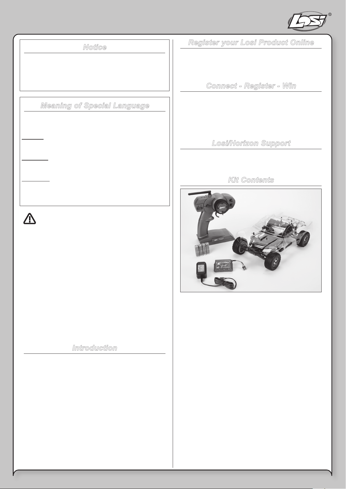
Kit Contents
WARNING: Read the ENTIRE instruction manual to
become familiar with the features of the product before
operating. Failure to operate the product correctly can result
in damage to the product, personal property and cause
serious injury.
This is a sophisticated hobby product and NOT a toy. It must
be operated with caution and common sense and requires
some basic mechanical ability. Failure to operate this Product
in a safe and responsible manner could result in injury or
damage to the product or other property. This product is not
intended for use by children without direct adult supervision.
Do not attempt disassembly, use with incompatible
components or augment product in any way without the
approval of Horizon Hobby, Inc. This manual contains
instructions for safety, operation and maintenance. It is
essential to read and follow all the instructions and warnings
in the manual, prior to assembly, setup or use, in order to
operate correctly and avoid damage or serious injury.
Introduction
Thank you for choosing the Mini SCT from Losi. This guide
contains the basic instructions for operating your new Mini
SCT. It is critical that you read all of the instructions in order
to operate your model correctly and avoid unnecessary
damage.
• 1/16th Scale Mini SCT
• Losi® Radio System with Spektrum™ 2.4GHz DSM
• 4 AA batteries (for transmitter)
• Losi 7.2V 1100mAh NiMH Pack with EC2™ connector
• Losi AC wall charger (110V)
®
2 - EN
The Spektrum trademark is used with
permission of Bachmann Industries, Inc.
Losi, DSM, EC2 are trademarks or registered
trademarks of Horizon Hobby, Inc.
Page 3
Charging Warnings and Precautions
Failure to exercise caution while using this product and
comply with the following warnings could result in product
malfunction, electrical issues, excessive heat, FIRE, and
ultimately injury and property damage.
• Read all safety precautions and literature prior to use of
this product.
• Never leave the battery and charger unattended during
use.
• Never attempt to dismantle the charger.
• Never attach your charger to both an AC and DC power
source at the same time.
• Never reverse the positive and negative terminals.
Wrong connection will damage the battery and may
cause damage to the charger.
• Never allow minors to charge battery packs
• Never drop charger or batteries.
• Never attempt to charge dead or damaged batteries
• Never attempt to charge a battery pack containing
different types of batteries.
• Never charge a battery if the cable has been pinched or
shorted.
• Never allow batteries or battery packs to come into
contact with moisture at any time.
• Never charge batteries in extremely hot or cold places
(recommended between 50-80 degrees F) or place in
direct sunlight.
• Always use only rechargeable batteries. This charger
cannot charge batteries such as “heavy duty,” “Alkaline
battery,” or “Mercury battery.”
• Always connect the positive red lead (+) and negative
black lead (-) terminals of the battery to the charger
terminals correctly.
• Always disconnect the battery after charging, and let the
charger cool between charges.
• Always inspect the battery before charging.
• Always terminate all processes and contact Horizon
Hobby if the product malfunctions.
• Always keep batteries and charger away from any
material that could be affected by heat (such as ceramic
and tile), as they can get hot.
• Always monitor the area, use a re alarm and have a re
extinguisher available at all times.
• Always make sure you know the specications of the
battery to be charged or discharged to ensure it meets
the requirements of this charger. If the program is set
up incorrectly, the battery and charger may be damaged.
Improper settings can cause the battery to become
overcharged potentially leading to re or explosion.
• Always connect the charge cable to the charger rst,
then connect the battery to avoid short circuit between
the charge leads. Reverse the sequence when
disconnecting.
• Never connect more than one battery pack to this
charger at a time.
• Always constantly monitor the temperature of the battery
pack while charging.
• Always end the charging process if the charger or
battery becomes hot to the touch or starts to change
form (swell) during the charge process.
Getting Started
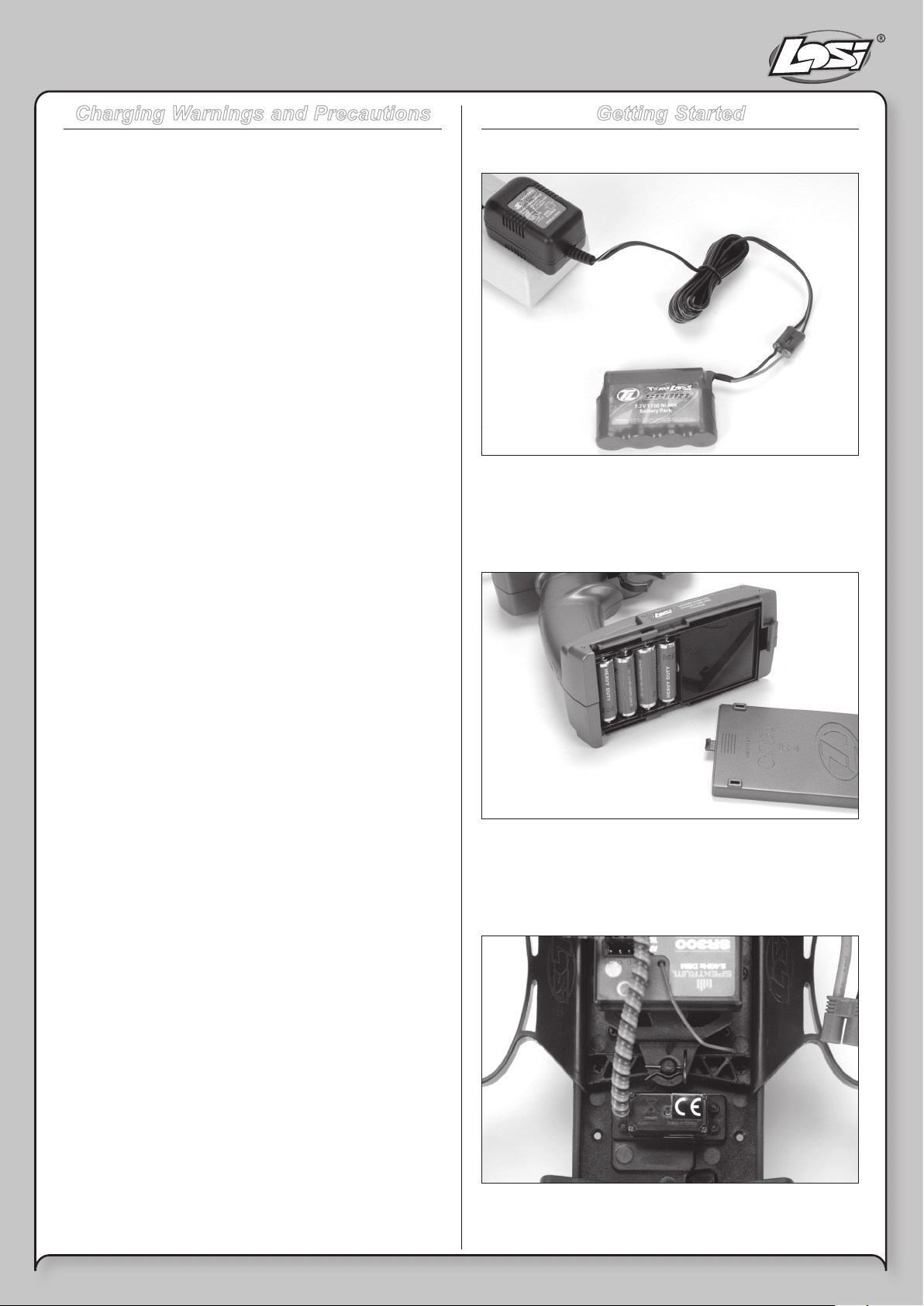
STEP 1
Plug the charger into the proper wall receptacle then the
battery into the charger and let it charge for 3 hours for the
rst time. For subsequent charges allow 5 to 6 hours for a full
charge.
STEP 2
Remove the transmitter battery cover, install four (4) AA
batteries and replace cover. Pay close attention to the
polarity of the positive (+) and negative (-) ends and replace
cover.
STEP 3
Once the battery is charged, remove the body clip from the
front battery hold-down and lift the battery strap.
3 - EN
Page 4
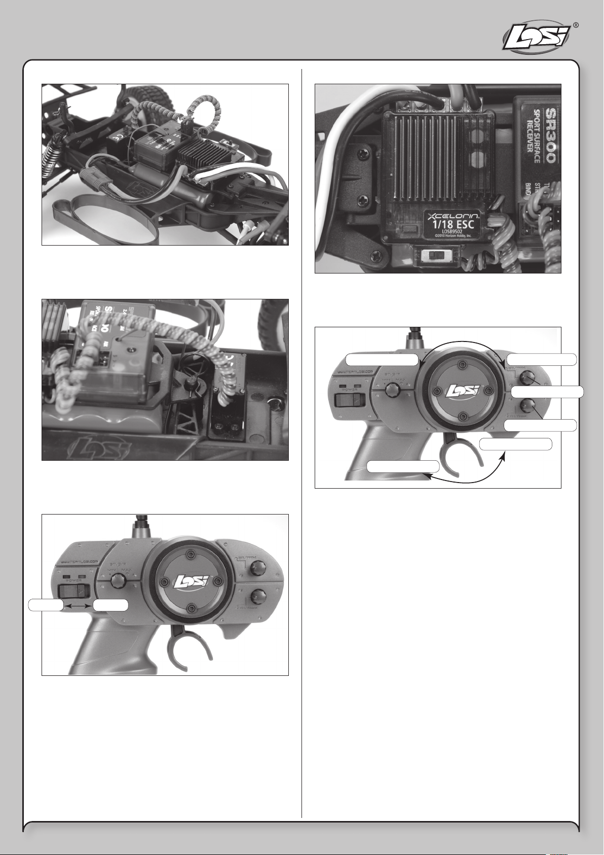
STEP 4
Install the charged battery pack into the chassis as shown.
Ensure the battery is laying at on the chassis.
STEP 5
STEP 7
Once the transmitter has been powered on, turn on your
vehicle by sliding the switch on the ESC to the “ON” position.
STEP 8
Reinstall the battery strap and body clip. Plug the battery
pack into the ESC.
STEP 6
Off
Off On
On
Left
Left Right
Brake/Reverse
Brake/Reverse
Forward
Forward
If the rear wheels turn during power-on, adjust the “TH. Trim”
knob located to the lower right of the steering wheel until they
stop.
To make the vehicle move forward, pull the trigger back. To
reverse the vehicle, wait for the model to stop and then push
the trigger forward.
When going forward the vehicle should move in a straight
line. If not, adjust the “ST. Trim” so that it tracks in a straight
line without having to turn the steering wheel.
Right
ST Trim
ST Trim
TH Trim
TH Trim
STEP 9
After you have nished, turn your vehicle off FIRST by sliding
the ESC switch to the “OFF” position. After the model has
been turned off, turn off the transmitter.
Always turn on the transmitter rst. The small red and green
lights above the switch should both light up. If not, you need
to check for low or incorrectly installed batteries.
STEP 10
If you wish to clean your vehicle, use compressed air and/or
a soft brush to remove dust and dirt. NEVER use chemicals
or anything wet as it can cause damage to both electronics
and plastic parts.
4 - EN
Page 5

ALWAYS:
• Turn on the transmitter before the vehicle
• Use caution when running your vehicle near people
• Turn both the vehicle and transmitter “OFF” when done
• Check the battery condition of the transmitter before
running
NEVER:
• Operate the vehicle with low battery power
• Run the vehicle through water or wet grass
• Use chemicals to clean the chassis
• Run the vehicle without a gear cover
Safety Precautions
Losi and Horizon Hobby shall not be liable for any loss or
damages, whether direct, indirect, special, incidental, or
consequential, arising from the use, misuse, or abuse of this
product or any product required to operate it.
Age Recommendation
Not for children under 14 years. This is not a toy.
• This model is controlled by a radio signal subject to
interference from many sources outside your control.
This interference may cause momentary loss of control
so it is advisable to always keep some distance in all
directions around your model as a safety margin to
avoid collisions.
• Always operate your model in an open area away from
cars, trafc and people.
• Avoid running your model in the street where damage
can occur.
• Never run your Mini SCT with low transmitter batteries.
• Carefully follow the directions and warnings for this and
any optional support equipment.
• Keep all chemicals, small parts and anything electrical
out of the reach of children.
Tools and Items You Will Find Handy
• Soft bristle brush for cleaning
• 5.5mm nut driver for the wheel nuts
• #0 or #1 Phillips screwdriver
• LOSA99100 .050-inch Hex Wrench
Note: Use only Losi tools or other high-quality tools. Use of
inexpensive tools can cause damage to the small screws and
parts used on this type of model.
The Radio System
The following is an overview of the various functions and
adjustments found on your Losi Mini SCT radio system.
Since the Mini SCT operates on a radio signal, it is important
for you to read and understand these functions before driving
the model.
THE RECEIVER
8
9
10
2
1
3
7
4
6
5
1. Receiver/ESC Power Lead: Connects to the battery lead
for power
2. Servo Port/Plug: Where the steering servo plugs in (note
polarity on case)
3. Bind port: Used to bind the receiver to the transmitter
4. Indicator Light: Indicates the operation status of the
receiver
5. On/Off Switch: Controls Power to the Receiver/ESC
6. Setup Button: Enters ESC into setup mode
7. Battery Leads: Connects the battery to the ESC
8. Motor Lead: Connects the ESC to the motor
9. Antenna Wire: Receives the radio signal from your
transmitter
10. Aux. Port
5 - EN
Page 6
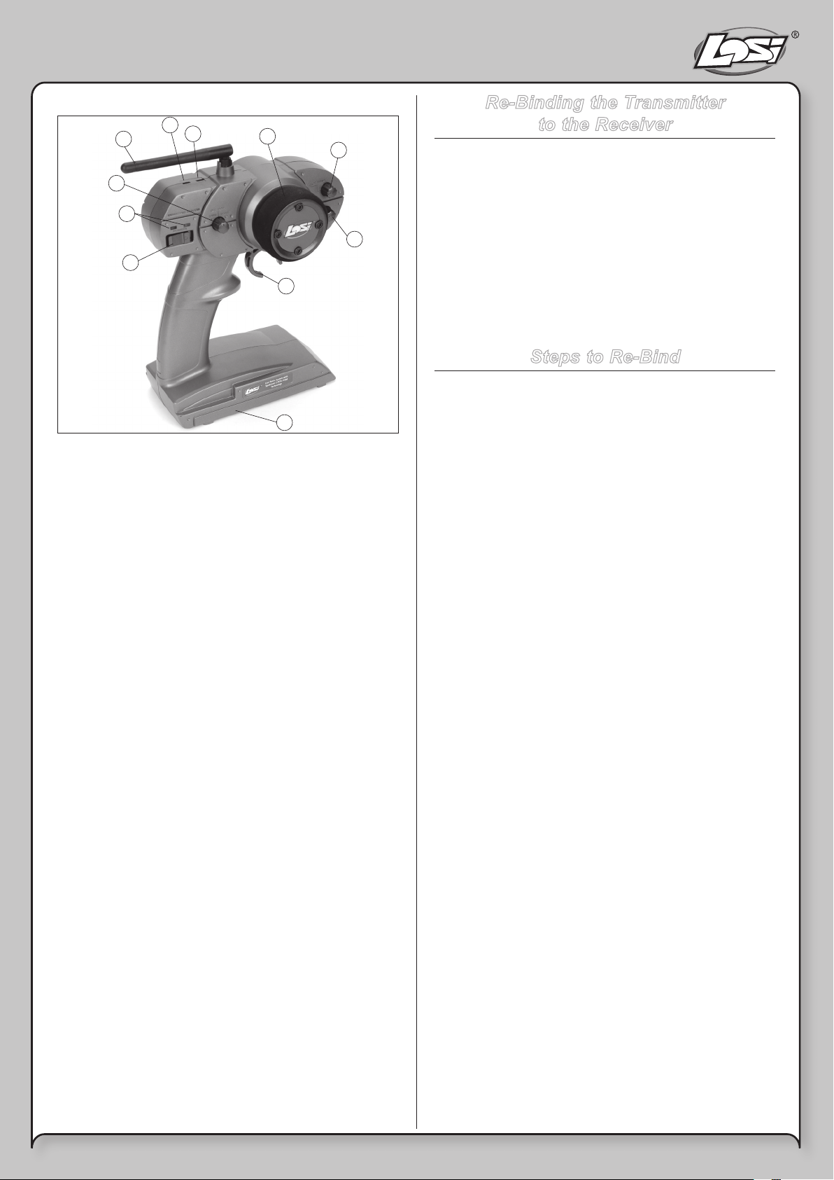
THE TRANSMITTER
9
3
8
5
4
10
1. Steering Wheel: Controls direction (left/right) of the
model.
2. Throttle Trigger: Controls speed and direction (forward/
reverse) of the model.
3. Antenna: Transmits signal to the model.
4. On/Off Switch: Turns the power on/off for the transmitter.
5. Indicator Lights: Green (right) light indicates adequate
battery power. Red (left) indicates signal strength.
6. ST. Trim: Adjusts the “hands off” direction of the model.
7. TH. Trim: Adjusts the motor speed to stop at neutral.
8. Steering Rate: Adjusts amount front wheels move when
the steering wheel is turned left and right.
9. ST. REV: Reverses the function of the steering when the
wheel is turned left or right.
10. TH. REV: Reverses the function of the speed control
when pulled back or pushed forward.
11. Bottom Cover: Covers and holds the batteries that
power the transmitter.
1
6
7
2
11
Re-Binding the Transmitter
to the Receiver
The Losi DSM radio system included in the Mini SCT
operates on 2.4GHz. The communication between the
transmitter and receiver starts in the few seconds after the
transmitter and vehicle are both turned on. This is called
the “binding process”. The Losi DSM radio system will not
interfere with previous technology radio systems that operate
on 27MHz or 75MHz frequencies and you will not receive any
interference from them. Although set at the factory, below are
the steps required to re-bind your transmitter to the receiver
should the need arise. During the bind process there is a
unique ID from the transmitter communicated to the receiver
to ensure trouble-free radio operation.
Steps to Re-Bind
1. Ensure the transmitter and vehicle are both turned off.
2. Using the supplied Bind plug (which looks like a
standard receiver plug with a wire loop installed) insert
or plug into the receiver slot labeled “BIND”. Looking
down on the receiver this slot would be below the LED
and is the furthest from the LED, or nearest to the corner
of the receiver.
Note: You do not need to remove any
of the other plugs to re-bind.
3. With the Bind plug installed, turn on the vehicle. Notice a
blinking Orange LED within the receiver.
4. Now you are ready to turn on the transmitter. You should
notice on the back of the transmitter a similar blinking
Orange LED under the translucent cover.
5. Both the receiver and transmitter blinking Orange LEDs
will stop blinking and become solid indicating they have
“bound” themselves together.
6. Please turn off both the vehicle and transmitter to
remove the Bind plug from the receiver. Failing to
remove the Bind plug will cause the transmitter to
attempt to rebind every time you turn on the vehicle and
transmitter.
7. Turn on both the vehicle and transmitter to ensure
operation. If the transmitter does not control the vehicle,
please repeat steps 1 to 6. Should this not correct the
problem please call Horizon Service/Repair for further
assistance.
8. The Bind process is complete. Your vehicle’s radio
system should be ready for use.
6 - EN
Page 7

Resetting and adjusting the
FEATURES
MSC-18BL ESC
Battery Type Programming
1. LED indicator
After power is turned on, the LED will display the selected
Battery Type for 2 seconds.
Red and Green LEDs are used to display selected Battery
Type:
Red LED Flashing = LiPo is selected
Green LED Flashing = NiMH is selected
To change from one battery type to another (colors described
above), press the setup button during the rst 2 seconds
after turning on ESC. Cutoff voltage will automatically adjust
based on battery type:
For LiPo battery: ESC will auto detect whether it is 1 cell
(3.3V), 2 cell (6V) or 3 cell (9V)
For NiMH: ESC will cutoff at 4.3V
2. LED display during “Normal Operation”
1. Auto Detects Brushed or Brushless motor (See Select
Motor Type)
2. One-Touch Endpoints calibration
3. Battery Selection:
a. LiPo (ESC auto detects number of cell:
1S to 3S)
b. NiMH
4. 2 ESC prole:
a. Forward / Reverse with Smart Brake II
b. Forward Only
5. Battery Over Voltage Protection (Max Input voltage =
13V)
6. Thermal Protection
7. Motor Stall Detection
Speed Control Programming
Select Motor Type
When ESC is turned on, it will check the connection
between Red and White wire. If the wires are shorted,
then it will go into brushed motor mode.
Brushed Motor
a. Motor (+) connected to Red and White Wire of ESC
b. Motor (-) connected to Black Wire of ESC
Brushless Motor
Connect the 3 motor wires to Red, White and Black wire of
ESC.
Condition
Stop
Partial Forward
Max Forward
Partial Reverse
Max Reverse
Brake
3. One-Touch Endpoints Calibration Programming:
a. Turn on Transmitter, Throttle in neutral position
b. Hold the ESC setup button and turn on ESC
c. Red and Green LED will turn on, release setup
button
d. Green LED will begin ashing, pull trigger to full
throttle position until Green light turns solid, then
return to neutral position
e. Red LED will ash at this time
f. Push trigger to at maximum reverse position until
Red LED turns solid
g. Release trigger to neutral position and programming
is complete
4. LED display for “Error”
a. Battery Voltage too high (over 13V)---Solid Red LED
and Green LED ashing slowly (Only during Power
ON)
b. Overheat---Alternatively Flashing Red and Green
c. Motor Failure, e.g., wire broken, bad motor, or
jam---Red LED ashing quickly 3 times (repeating
sequence)
d. Battery Low---Green LED solid on and Red LED
ashing slowly
LED
Green
Off
Red
Off
Red
Red & Green
5. Technical Specication:
1. Sensorless Brushless ESC
2. Resistance per phrase: 0.0036 ohm
3. Up to 25A continuous current, 250A surge current
4. Max RPM: 120,000
5. 4 to 7 cells NiMH, or 1, 2 or 3 cell Li Polymer
6. BEC: 6V, 1A
7 - EN
Page 8

Warning
This model may only be powered by the stock 6-cell 7.2volt NiMH battery pack (LOSB1212), a 2-cell 7.4-volt LiPo
battery pack (LOSB9826) or 3-cell 11.1 volt LiPo battery pack
(LOSB9827). Please consult the Motor/Battery Chart below
for suggested motor/battery combos. The use of higher
voltage battery packs will cause ESC damage and void
any warranty. Consult your local hobby dealer or check
www.losi.com.
4100
4500
5000
7.2V NiMH (LOSB1212)
7.4V LiPo (LOSB9826)
11.1V LiPo (LOSB9827)
(LOSB9458)
x
x
x
(LOSB9457)
x
x
x
(LOSB9459)
x
x
x
6000
(LOSB9460)
x
x
(LOSB9461)
7400
x
x
8200
(LOSB9462)
x
x
9400
(LOSB9463)
x
x
Chassis Tuning
The Mini SCT has several adjustments available to you for
tuning the performance for your needs. Although there are
multiple shock positions and camber link locations provided,
we have built the model with the best overall settings. The
following are simple adjustments and easily maintained
settings to assure proper operation and performance. It is
advised when making any adjustment that you do so in small
increments and always check for other parts of the chassis
that are affected.
Slipper Adjustments
The Mini SCT is equipped with a slipper device offering
both traction control and protection for the transmission.
The slipper is primarily used to help absorb sudden impacts
on the drivetrain due to landing big jumps or when using
more powerful aftermarket motors and/or battery packs.
Additionally, it can be used to smooth out the ow of power
to the rear wheels and limit wheel spin when running on
extremely slick surfaces.
When adjusted properly, you should be able to hold the rear
tires rmly and barely be able to push the spur gear forward
with your thumb.
To track test, turn the Mini SCT on and place it on the
ground. As you push it backwards allowing it to roll freely,
punch the throttle. The slipper should slip no more than an
inch or two as it accelerates. With the included motor and
battery pack it should slip just a little. Make sure you replace
the gear cover before running.
Steering Rate
Your transmitter is equipped with a steering rate control to
the left of the steering wheel. This advanced feature, usually
found only on competition-type radios, allows you to adjust
the amount the front tires move when you turn the steering
wheel. This is really helpful when you are on slick, as well as
high-traction surfaces.
Less Rate
Increase
Slip
Reduce
Slip
Adjustment is made by turning the 3mm adjustment nut
clockwise (to the right) to reduce the slip, or counterclockwise
(to the left) to increase the slip.
8 - EN
If your Mini SCT turns too sharply and/or spins out easily,
try turning the steering rate down by rotating the knob
counterclockwise (to the left).
Page 9

More Rate
For sharper or additional steering, try turning the knob
clockwise (to the right).
Toe-In
This is the relationship of the left and right side tire to one
another.
Camber
Camber is the angle of the tires to the racing surface when
viewed from the front or rear of the truck.
Less Camber More Camber
You want to keep both the front and rear tires straight up and
down or leaning in at the top very slightly.
If you are running on carpet or similar high traction surfaces,
you may nd leaning the tires in a bit more helps. This
adjustment is made with the threaded links extending from
the front or rear bulkhead to the spindle carrier or rear hub.
Making the camber rods shorter increases the camber and
lean-in of the tire, while making the camber rods longer
decreases the camber.
Less Toe-In More Toe-In
Ideally, you want the front of the tires to be pointed inward
toward each other just slightly when viewed from above. This
makes the model track straight and stable. This is controlled
with the threaded steering rods on either side. As you make
them longer you will increase the toe-in and vice versa.
Ride Height
This is the height the chassis sits and runs at. Spring spacers
included with the Mini SCT, when installed between the
shock top and spring, will increase the pre-load on the spring
and raise the chassis. You may want to try this when running
on extremely rough surfaces.
Service/Repair
Radio/Speed Control & Motor
If you have any problems other than those covered in
the troubleshooting section, please call the appropriate
electronics service department. They will be able to give your
specic problem additional attention and instruct you as to
what needs to be done.
Maintenance
If you have any questions other than those covered in the
troubleshooting or maintenance sections, please call the
appropriate Horizon product support department.
Cleaning
Performance can be hindered if dirt gets in any of the moving
suspension parts. Use compressed air, a soft paintbrush, or
toothbrush to remove dust or dirt. Avoid using solvents or
chemicals as they can actually wash dirt into the bearings or
moving parts as well as cause damage to the electronics.
9 - EN
Page 10

Rebuilding the Differential
Reassembly
The gears in the differential will wear over time. The same
is true for the outdrives, driveshafts, and rear axles. We
suggest using a small rag or paper towel to lay out the parts
you remove to make it easier to reassemble.
Disassembly
1. Unplug the 3 motor wires from ESC.
2. Remove the gear cover (three screws pictured)
3. Remove the 2 screws on the front of the rear shock
tower that attach to the rear upper cage. Once the
screws are removed, rotate the rear cage toward the
rear enabling access to the rear camber block.
4. Remove the 2 screws attaching the rear camber block to
the transmission case.
5. Remove 4 screws from rear skid plate and remove
transmission from vehicle.
6. Remove bracket on top of transmission by removing the
2 front screws and removing the long screw (secured
with a bolt), which passes through the transmission from
the motor plate side.
7. Remove the left side of the gearbox by removing the
three screws.
8. Remove any shims on the bevel gears (not used on all
models) and set them aside so they can be reinstalled in
the same location.
9. Carefully remove the large plastic sun gear and the
bevel gears on either side of it. You can use the
removed differential assembly as a guide for putting
together the replacement unit. For the best performance
Losi Grease (LOSA3066) can be applied to these gears.
10. Remove the center mounted idler gear from the
gearbox. Remove the shaft and push the ball bearings
out of both sides. Install these bearings in the new gear.
Replace the idler gear and shaft into the center of the same
right side of the gearbox. Replace any shims removed from
the right bevel gear and slide it through the lower bearing.
Replace any shims that came off of the left side bevel gear
and allow it to slide through the lower bearing as you put the
left gearbox half back into position. Replace the screws and
reinstall the rebuilt gearbox using the above steps in reverse
order. Consult the exploded view in the back of this manual
for more details.
Changing the Spur Gear
Remove the gear cover by removing the three small screws.
If you are replacing the spur gear with one of a different size
(number of teeth), you must rst loosen (do not remove) the
two screws that secure the motor and slide it back slightly.
Remove the 3mm nut at the end of the slipper shaft and all
of the slipper parts on the outside of the spur gear as well
as the old gear. Place the new spur gear into position and
replace the slipper parts. If you have changed the size of
the spur, see Setting the Gear Mesh below. After you have
changed the spur gear, you will have to adjust the slipper as
described elsewhere.
Changing the Pinion Gear/Gear Ratio
Before you change the pinion gear ask yourself why you are
doing it. In general, if you change to a larger pinion the top
speed will improve but you will see less acceleration and
run time. This would only be advisable for really long track
layouts with few tight turns. Changing to a smaller pinion
will give you quicker acceleration and possibly a bit longer
run time but a little less top speed. This would be good for
short layouts or when running hotter motors. The pinion on
the Mini SCT offers the best balance of both. To change the
pinion, remove the gear cover, loosen the motor screws, and
slide the motor back. Use a pair of small needle-nose pliers
between the motor plate and back of the pinion to push the
pinion off. Place the new pinion on the end of the motor shaft
and, using the at of the pliers or a similar at tool, push it
on to the same position as the one removed. See Setting the
Gear Mesh below.
CAUTION: When running aftermarket motors, check
with the motor manufacturer for correct gearing. Never
over-gear the motor as it can cause overheating, damaging it
and the speed control.
Setting the Gear Mesh
The motor screws should be slightly loose. Slide the motor
forward allowing the pinion gear to mesh with the spur gear.
Snug (not tight) the bottom motor screw and try rocking the
spur back and forth. There is a slight bit of movement before
the motor is forced to turn over. If not, pull the top of the
motor back slightly and recheck. If there is too much slop
between the gears, push the top of the motor forward. When
set properly, the wheels can be spun forward freely with
very little noise. Make sure to tighten both motor screws and
replace the gear cover before running.
10 - EN
Page 11

Steering Servo Installation/Removal
Unplug the servo lead from the receiver. Remove the four
small screws located on the bottom of the chassis that
secure the servo to the chassis. Use a screwdriver or small
pliers to pop the steering link off of the servo, so it can be
removed. Replace in the reverse sequence used to remove
the servo.
Receiver/Speed Control (ESC)
Installation/Removal
Unplug the power lead, motor leads and steering servo. Do
not attempt to open the receiver or electronic speed control
(ESC) as only a factory technician has the proper tools
and parts to make any repairs necessary. The receiver and
ESC are mounted with double-sided foam tape. Use your
thumb and index nger at the bottom of the front corners
to pull them from the mount. If this is difcult, ask for help.
If necessary, carefully use a large at blade screwdriver
between the unit and the mount to pry it loose. Make
sure you remove any left over foam or adhesive before
remounting with common servo tape or hobby type foam
tape.
Warranty and Repair Policy
WARRANTY PERIOD
Exclusive Warranty- Horizon Hobby, Inc., (Horizon)
warranties that the Products purchased (the “Product”) will
be free from defects in materials and workmanship at the
date of purchase by the Purchaser.
LIMITED WARRANTY
Horizon reserves the right to change or modify this
warranty without notice and disclaims all other
warranties, express or implied.
(a) This warranty is limited to the original Purchaser
(“Purchaser”) and is not transferable. REPAIR OR
REPLACEMENT AS PROVIDED UNDER THIS WARRANTY
IS THE EXCLUSIVE REMEDY OF THE PURCHASER. This
warranty covers only those Products purchased from an
authorized Horizon dealer. Third party transactions are not
covered by this warranty. Proof of purchase is required for all
warranty claims.
(b) Limitations- HORIZON MAKES NO WARRANTY OR
REPRESENTATION, EXPRESS OR IMPLIED, ABOUT
NON-INFRINGEMENT, MERCHANTABILITY OR FITNESS
FOR A PARTICULAR PURPOSE OF THE PRODUCT.
THE PURCHASER ACKNOWLEDGES THAT THEY
ALONE HAVE DETERMINED THAT THE PRODUCT
WILL SUITABLY MEET THE REQUIREMENTS OF THE
PURCHASER’S INTENDED USE.
(c) Purchaser Remedy- Horizon’s sole obligation hereunder
shall be that Horizon will, at its option, (i) repair or (ii) replace,
any Product determined by Horizon to be defective. In
the event of a defect, these are the Purchaser’s exclusive
remedies. Horizon reserves the right to inspect any and
all equipment involved in a warranty claim. Repair or
replacement decisions are at the sole discretion of Horizon.
This warranty does not cover cosmetic damage or damage
due to acts of God, accident, misuse, abuse, negligence,
commercial use, or modication of or to any part of the
Product. This warranty does not cover damage due to
improper installation, operation, maintenance, or attempted
repair by anyone other than Horizon. Return of any Product
by Purchaser must be approved in writing by Horizon before
shipment.
DAMAGE LIMITS
HORIZON SHALL NOT BE LIABLE FOR SPECIAL,
INDIRECT OR CONSEQUENTIAL DAMAGES, LOSS OF
PROFITS OR PRODUCTION OR COMMERCIAL LOSS IN
ANY WAY CONNECTED WITH THE PRODUCT, WHETHER
SUCH CLAIM IS BASED IN CONTRACT, WARRANTY,
NEGLIGENCE, OR STRICT LIABILITY. Further, in no event
shall the liability of Horizon exceed the individual price of
the Product on which liability is asserted. As Horizon has
no control over use, setup, nal assembly, modication
or misuse, no liability shall be assumed nor accepted for
any resulting damage or injury. By the act of use, setup or
assembly, the user accepts all resulting liability.
If you as the Purchaser or user are not prepared to accept
the liability associated with the use of this Product, you
are advised to return this Product immediately in new and
unused condition to the place of purchase.
Law: These Terms are governed by Illinois law (without
regard to conict of law principals).
Warranty Services
QUESTIONS, ASSISTANCE, AND REPAIRS
Your local hobby store and/or place of purchase cannot
provide warranty support or repair. Once assembly, setup
or use of the Product has been started, you must contact
Horizon directly. This will enable Horizon to better answer
your questions and service you in the event that you may
need any assistance. For questions or assistance, please
direct your email to productsupport@horizonhobby.com, or
call 877.504.0233 toll free to speak to a Product Support
representative. You may also nd information on our website
at www.horizonhobby.com.
11 - EN
Page 12

INSPECTION OR REPAIRS
If this Product needs to be inspected or repaired, please
use the Horizon Online Repair Request submission process
found on our website or call Horizon to obtain a Return
Merchandise Authorization (RMA) number. Pack the Product
securely using a shipping carton. Please note that original
boxes may be included, but are not designed to withstand
the rigors of shipping without additional protection. Ship
via a carrier that provides tracking and insurance for lost
or damaged parcels, as Horizon is not responsible for
merchandise until it arrives and is accepted at our facility. An
Online Repair Request is available at www.horizonhobby.com
http://www.horizonhobby.com under the Repairs tab. If you
do not have internet access, please contact Horizon Product
Support to obtain a RMA number along with instructions for
submitting your product for repair. When calling Horizon, you
will be asked to provide your complete name, street address,
email address and phone number where you can be reached
during business hours. When sending product into Horizon,
please include your RMA number, a list of the included items,
and a brief summary of the problem. A copy of your original
sales receipt must be included for warranty consideration.
Be sure your name, address, and RMA number are clearly
written on the outside of the shipping carton.
NOTICE: Do not ship batteries to Horizon. If you
have any issue with a battery, please contact the
appropriate Horizon Product Support ofce.
WARRANTY INSPECTION AND REPAIRS
To receive warranty service, you must include your
original sales receipt verifying the proof-of-purchase
date. Provided warranty conditions have been met, your
Product will be repaired or replaced free of charge. Repair or
replacement decisions are at the sole discretion of Horizon.
NON-WARRANTY REPAIRS
Should your repair not be covered by warranty the
repair will be completed and payment will be required
without notication or estimate of the expense unless
the expense exceeds 50% of the retail purchase
cost. By submitting the item for repair you are agreeing to
payment of the repair without notication. Repair estimates
are available upon request. You must include this request
with your repair. Non-warranty repair estimates will be billed
a minimum of ½ hour of labor. In addition you will be billed for
return freight. Horizon accepts money orders and cashiers
checks, as well as Visa, MasterCard, American Express,
and Discover cards. By submitting any item to Horizon for
inspection or repair, you are agreeing to Horizon’s Terms and
Conditions found on our website under the Repairs tab.
UNITED STATES
(Electronics and engines)
Horizon Service Center
4105 Fieldstone Rd
Champaign, Illinois
61822 USA
Online Repair Request visit:
www. horizonhobby.com/repairs
877-504-0233
(All other products)
Horizon Product Support
4105 Fieldstone Rd
Champaign, Illinois
61822 USA
productsupport@horizonhobby.com
877-504-0233
UNITED KINGDOM
Horizon Hobby Limited
Units 1-4 Ployters Rd
Staple Tye
Harlow, Essex
CM18 7NS
United Kingdom
sales@horizonhobby.co.uk
+44 (0) 1279 641 097
GERMANY
Horizon Technischer Service
Hamburger Str. 10
25335 Elmshorn
Germany
service@horizonhobby.de
+49 4121 46199 66
FRANCE
Horizon Hobby SAS
14 Rue Gustave Eiffel
Zone d’Activité du Réveil Matin
91230 Montgeron
infofrance@horizonhobby.com
+33 (0) 1 60 47 44 70
12 - EN
Page 13

Compliance Information for the
European Union
DECLARATION OF CONFORMITY
(in accordance with ISO/IEC 17050-1)
No. HH2010081901
DISPOSAL OF WEEE BY USERS
IN THE EUROPEAN UNION
Product(s): 1/16 Mini Stronghold SCT RTR
Item Number(s): LOSB0211i
Equipment class: 1
The object of declaration described above is in conformity
with the requirements of the specications listed below,
following the provisions of the European R&TTE directive
1999/5/EC:
EN 300-328 Technical requirements for
Radio equipment.
EN 301 489 General EMC requirements
EN 60950 Safety
Signed for and on behalf of:
Horizon Hobby, Inc.
Champaign, IL USA
Aug 19, 2010
Steven A. Hall
This product must not be disposed of with other waste. Instead,
it is the user’s responsibility to dispose of their waste equipment
by handing it over to a designated collection point for the
recycling of waste electrical and electronic equipment. The
separate collection and recycling of your waste equipment at
the time of disposal will help to conserve natural resources and
ensure that it is recycled in a manner that protects human health
and the environment. For more information about where you can
drop off your waste equipment for recycling, please contact your
local city ofce, your household waste disposal service or where
you purchased the product.
FCC Information
This device complies with part 15 of the FCC rules. Operation
is subject to the following two conditions: (1) This device may
not cause harmful interference, and (2) this device must accept
any interference received, including interference that may cause
unde-sired operation.
Caution: Changes or modications not expressly approved
by the party responsible for compliance could void the user’s
authority to operate the equipment.
This product contains a radio transmitter with wireless
technology which has been tested and found to be compliant
with the ap-plicable regulations governing a radio transmitter in
the 2.400 GHz to 2.4835 GHz frequency range.
Vice President
International Operations and Risk Management
Horizon Hobby, Inc.
13 - EN
Page 14

Rebuilding/Refilling the Shocks
Step 1
After removing the shock,
push up on the lower spring
cup and remove it from the
shaft. Remove the spring and
preload spacers.
Step 2
Turn the shock upside down
and remove the black shock
cartridge/shaft assembly
from the shock body by
turning it counterclockwise.
Note: If you only wish to
change or fill the shock fluid,
skip to step 5.
Step 5
If you plan on completely
changing the shock fluid
(suggested), dump out the
old fluid from the shock body.
Carefully fill the shock body
with fluid to the bottom of the
threads inside the shock body.
Step 6
Pull the shaft out so the
piston is next to the
cartridge and reinstall the
assembly into the shock
body. Turn in a clockwise
direction until snug—DO NOT
TIGHTEN yet!
Step 3
Remove the top E-clip from the
shock shaft. Remove the shock
piston. Remove second E-clip.
Remove the old cartridge.
Put a drop of oil on the shock
shaft before installing a new shock
cartridge.
Step 4
Reinstall the lower E-clip.
Slide the shock piston onto
the shock shaft against the
E-clip. Reinstall the top E-clip.
Step 7
Turn the shock over and use a #0 Phillips
screwdriver to remove the small bleed
screw at the top of the shock. Slowly push
the shock shaft up until it stops. Excess fluid
should flow out of the bleed hole. Slowly pull
the shock shaft halfway back and replace
the bleed screw. Use pliers to tighten the
cartridge, being careful not to strip the
plastic lobes on the cartridge.
Step 8
Replace the spring and
spring cup and test the shock
action for smoothness and
leaks. Retighten the bleed
screw or cartridge if either
leaks. Remount the shock on
your truck.
Note: Production shocks may differ slightly from those shown
in the drawings.
14 - EN
Page 15

VEHICLE TROUBLESHOOTING GUIDE
Symptom Possible Cause(s) Possible Solution(s)
Doesn’t operate
Motor runs but rear
wheels don’t move
Steering doesn’t work
Won’t turn in one direction
Motor doesn’t run
ESC gets hot
Poor run time
and/or sluggish acceleration
Poor range and/or glitching
Battery not charged or plugged in
Receiver switch not “On”
Transmitter not “On” or low battery
Pinion not meshing with spur gear
Pinion spinning on motor shaft
Slipper too loose
Transmission gears stripped
Charge battery/plug in
Turn on receiver switch
Turn on/replace batteries
Adjust pinion/spur mesh
Replace pinion gear on motor
Check & adjust slipper
Replace transmission gears
Check and replace drive pin
Servo plug not in receiver
Servo gears or motor damaged
Check if plug in/in all the way
Replace or repair servo
Servo gears damaged Replace servo
Motor plugs loose
Motor wire broken
ESC damaged
Motor over-geared
Driveline bound up
Plug in completely
Repair or replace as needed
Contact Horizon Hobby Product Support
Use smaller pinion on motor
Check wheels, suspension,
and transmission for binding
NiMH pack not fully charged
Charger not allowing full charge
Slipper slipping too much
Motor worn out
Driveline bound up
Recharge battery
Try another charger
Check/adjust slipper
Replace motor
Check wheels and transmission
for binding
Transmitter batteries low
Transmitter antenna loose
Vehicle battery low
Loose plugs or wires
Check and replace
Check and tighten
Recharge or replace
Check motor and power plugs
Slipper won’t adjust
Drive pin missing in shaft
Spur gear face worn out
Replace drive pin
Replace spur gear and adjust slipper
Recommended Motor and Battery Chart
7.2V NiMH (LOSB1212)
7.4V LiPo (LOSB9826)
11.1V LiPo (LOSB9827)
4100
(LOSB9458)
x
x
x
4500
(LOSB9457)
x
x
x
5000
(LOSB9459)
x
x
x
6000
(LOSB9460)
x
x
7400
(LOSB9461)
x
x
8200
(LOSB9462)
x
x
9400
(LOSB9463)
x
x
Warning
This model may only be powered by the stock 6-cell 7.2-volt NiMH battery pack (LOSB1212), a 2-cell 7.4-volt LiPo battery
pack (LOSB9826) or 3-cell 11.1 volt LiPo battery pack (LOSB9827). Please consult the Motor/Battery Chart above for
suggested motor/battery combos. The use of higher voltage battery packs will cause ESC damage and void any warranty.
Consult your local hobby dealer or check www.losi.com.
15 - EN
Page 16

Replacement Parts
LOSB0805 Losi DSM Transmitter
LOSB0813 MS20DSL Servo with Long Lead
LOSB1009 Main Chassis
LOSB1018 Front Bulkhead, Kickplate & Brace
LOSB1020 F/R Pivot Block Set
LOSB1024 F/R Suspension Arm Set
LOSB1027 Spindle, Carrier & Rear Hub Set
LOSB1029 Steering Bellcrank Set
LOSB1037 Front Axle & Pin Brace Set
LOSB1040 Camber & Steering Link Set
LOSB1041 Suspension Pin Set
LOSB1043 E-Clips (10)
LOSB1045 Wheel Nuts & Drive Pins
LOSB1049 Rod End Set (14)
LOSB1051 Ball Stud Set (10)
LOSB1059 Transmission Case & Motor Plate Set
LOSB1060 Transmission Ball Bearing Set (7)
LOSB1061 Battery Hold Down Set
LOSB1063 Transmission Shaft Set
LOSB1064 Slipper Hardware Set
LOSB1065 Transmission Gear Set, Metal
LOSB1068 Spur Gear Set (50T & 60T)
LOSB1073 Outdrive/Dogbone/Rear Axle Set
LOSB1074 F/R Bumper and Mount/Support Set
LOSB1100 F/R Ball Bearing Set (8)
LOSB1212 7.2V 1100mAh NiMH Battery
with EC2 Connector
LOSB1260 Pinion Gear Set (9T–12T)
LOSB1291 Front Shock Springs (pr)
LOSB1292 Rear Shock Springs (pr)
LOSB1293 Front Shocks with Springs, Assm. (pr)
LOSB1294 Rear Shocks with Springs, Assm. (pr)
LOSB1295 Front Shock Body Set (pr)
LOSB1296 Rear Shock Body Set (pr)
LOSB1297 Front Shock Shaft Set (pr)
LOSB1298 Rear Shock Shaft (pr)
LOSB1299 F/R Shock Rebuild Kit (pr)
LOSB1850 Side Guard
LOSB1852 Front/Rear Shock Tower
LOSB1853 Front/Rear Ladder & Mount Set
LOSB1854 Front/Rear Bumper & Support Set
LOSB1855 Motor Plate
LOSB1856 Body Post, Gear Cover Set
LOSB1859 Fastener Set
LOSB1950 Front Mounted Tire
LOSB1951 Rear Mounted Tire
LOSB9457 4500Kv Sensorless Motor
LOSB9502 MSC-18BL Brushless ESC
SPMSR300 Spektrum 3-Channel Surface Receiver
Option Parts
LOSB1013 Track Dots, Neon Orange (12)
LOSB1100 F/R Ball Bearing Set (8)
LOSB1110 Aluminum Shock Set
LOSB1117 Front Spring Set for Oil Shocks
LOSB1119 Rear Spring Set for Oil Shocks
LOSB1125 Ball Differential, Assembled with Bearings
LOSB1206 AC Peak Charger (1 hour)
LOSB1226 Servo Saver Set
LOSB1230 Titanium Turnbuckle Set
LOSB1240 CV Driveshaft Set
LOSB1260 Pinion Gear Set, 9T-12T
LOSB1261 Pinion Gear Set, 13T-16T
LOSB1262 Pinion Gear Set, 17T-20T
LOSB1263 Pinion Gear Set, 14T, 16T, 18T, 20T
LOSB1264 Pinion Setscrew with Wrench
LOSB1322 Painted Body Set with Stickers,
ReadyLift/Geiser Painted Body Set
LOSB1323 Painted Body Set with Stickers, Rockstar
Painted Body Set
LOSB1326 Body Set with Stickers, Clear
LOSB1339 Sticker Set
LOSB9458 1/18th Xcelorin 4100Kv Brushless Motor
LOSB9459 1/18th Xcelorin 5000Kv Brushless Motor
LOSB9460 1/18th Xcelorin 6000Kv Brushless Motor
LOSB9461 1/18th Xcelorin 7400Kv Brushless Motor
LOSB9462 1/18th Xcelorin 8200Kv Brushless Motor
LOSB9463 1/18th Xcelorin 9400Kv Brushless Motor
LOSB9535 1/18th Xcelorin Brushless Electronics
Speed Control
LOSB9560 Xcelorin 6000Kv Brushless Combo
(requires setscrew, pinion)
LOSB9561 Xcelorin 7400Kv Brushless Combo
(requires setscrew, pinion)
LOSB9562 Xcelorin 8200Kv Brushless Combo
(requires setscrew, pinion)
LOSB9563 Xcelorin 9400Kv Brushless Combo
(requires setscrew, pinion)
LOSB9606 MultiPro Intelligent Balance Charger
LOSB9626 Mini Plug to EC2 Charger Adaptor
LOSB9826 7.4V 1300mAh 2S 15C LiPo Battery
LOSB9627 Tamiya to EC2 Charger Adaptor
LOSB9827 11.1V 1300mAh 2S 20C LiPo Battery
16 - EN
Page 17

Rear shock
part numbers
Front shock
part numbers
Complete
rear shock
LOSB1294
Complete
front shock
LOSB1293
1296
1295
1299
1298
1297
1292
1291
1299
1856
1299
1064
1068
LOSB1859
ALL FASTENERS
1856
1854
1852
1854
1853
1853
1051
1049
1041
1051
1040
1073
1043
1045
1041
1951
1100
1020
1037
1043
1024
1100
1051
1027
1073
1045
1853
1060
1060
1063
1855
9457
1950
1260
1073
1059
1065
1059
1073
1045
1323
1856
9502
SPMSR300
1852
1061
0813
1009
17 - EN
1853
1850
1853
1074
1029
1051
1029
1051
1049
1049
1040
1037
1049
1018
1049
1040
1027
1040
1037
1051
1043
1049
1024
1041
1051
1041
1020
1854
1100
1041
* All part numbers
prefixed by LOSB
Page 18

29727.i
800-0440
© 2010 Horizon Hobby, Inc.
Not responsible for typographical errors.
 Loading...