

Page 1

1/18TH SCALE ARR PRO VERSION OF
THE CHAMPIONSHIP WINNING XXX-T
Operations Manual
Introduction
Thank you for choosing the Mini-T Pro from Team Losi Sport. This model requires you to install
the Radio gear and fill the shocks with fluid. This guide contains these and the basic instructions
for operating your new Mini-T Pro. It is critical that you read all of the instructions and all accompanying printed material in order to operate your model correctly and avoid unnecessary damage.
Please take a moment to look them over before building the model.
Copyright 2004 Team Losi
A Division of Horizon Hobby Inc.
800-0249
RT 11-04
Page 2
Saftey Precautions
This is a sophisticated radio controlled model that must be operated with caution and common
sense.
Failure to operate your Mini-T Pro in a safe and responsible manner could result in damage to the
model and property. The Mini-T Pro is not intended for use by children without direct supervision.
Team Losi and Horizon Hobby shall not be liable for any loss or damages, whether direct, indirect,
special, incidental, or consequential, arising from the use, misuse, or abuse of this product or any
product required to operate it.
This model is controlled by a radio signal that is subject to interference from many sources
outside your control. This interference can cause momentary loss of control so it is advisable to
always keep a safety margin in all directions to aviod collisions.
Always operate your model in an open area away from cars, traffic and people
Never run out into the street for any reason.
Never run your Mini-T Pro with low transmitter batteries
Carefully follow the directions and warnings for this and any optional support equipment (chargers,
rechargable battery packs, etc.) that you use.
Keep all chemicals, small parts and anything electrical out of the reach of children.
Required Equipment
2 Channel Radio System with Receiver Electronic Speed Controller
Micro size Servo Battery and Charger
Radio Installation
You will need a receiver, electronic speed control (ESC), and micro steering servo to complete
your Mini-T Pro. If you do not already have these we suggest you use one of the newer smaller
receivers and ESC’s as it will be easier to fit these in the space available. All of the popular radio
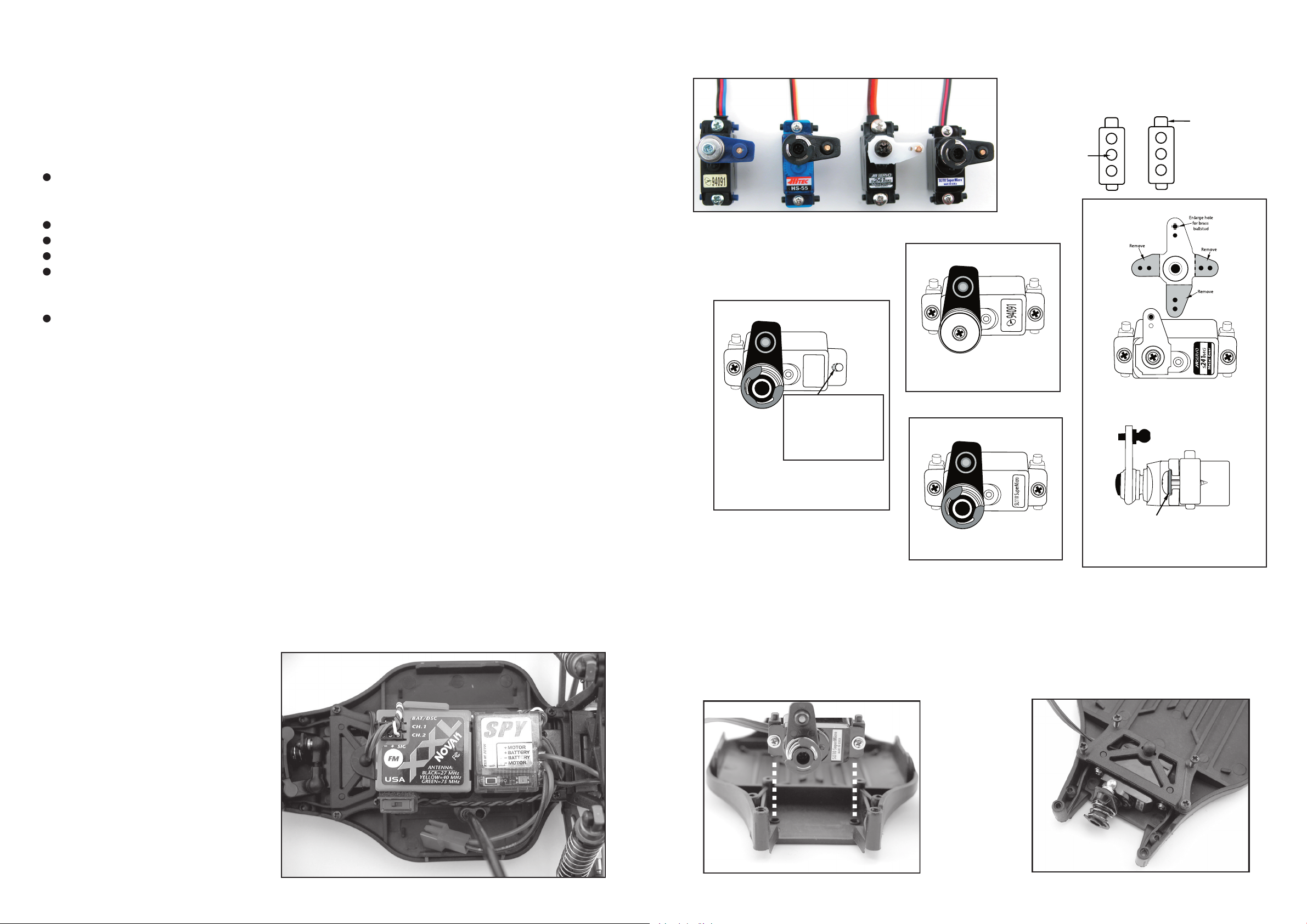
manufactures as well as Novak, GM Racing and LRP offer these items. We show mounting four of
the most popular steering servos. Please note that in most cases we suggest the use of a servo
saver as noted.
1) Cut a piece of double sided mounting tape to fit the bottom of both the receiver and ESC. Remove the paper backing from one side and apply to the bottom – Do Not remove the remaining
backing yet!
2) Test position the receiver and ESC on the top surface of the battery plate checking for adequate
clearance and convenient access for all wiring. Mark or note these positions before proceeding.
3) Remove the protective backing from the mounting tape on the receiver and ESC. Carefully
mount them on the battery plate.
Sample picture of electronics installed in the Mini-T Pro
Final Connections
Follow the radio manufactures instructions when making the final electronic
connections. Specifically, the orientation of the color-coded wires in the
various plugs where they plug into the
receiver. If you plan on removing the
wires attached to the motor mark the
endbell with a “+” at the red wire and “-“
at the black wire for future reference.
Follow the radio instructions to set the
proper steering and throttle movement.
Follow the instructions included with the
ESC for correct operation.
Recommended Servos
Installing the Servo
Be sure that
the taller pin
Use this hole
to mount
servos listed
Airtronics
94091Z
HiTec HS-55
To install this servo, use the included
Mini-T Servo Saver Kit and make
modifications to servo as pictured
above.
HiTEC
HS-55
c
te
i
H
Carefully using a hobby
knife, remove shaded
material to open servo
mounting hole as shown.
Do this modification on
both mounting “ears”.
JR Propo
S241MG
5
5
S
H
Expert Electronics
SL110
Airtronics 94091Z
To install this servo you will need to
purchase the Airtronics 98302 Micro
Servo Saver kit.
Expert Electronics SL110
To install this servo, use the included
Mini-T Servo Saver Kit.
JR Propo S241MG (Metal Gear)
At the time of this printing, a servo
saver was not available. Using only the
Metal geared version, follow the steps to
modify the servo horn.
LOSA6215 #4 Narrow Washer
To install this servo, you will need to purchase LOSA6215 #4 Narrow Washer to
space the mounting screw as pictured above.
Install the Servo into the Chassis as shown in Figure 1. Insert the pins on the Servo Mounting
Post into the holes in the Chassis. Move the Servo Posts slightly until both the left and right Posts
are inserted in the holes in the Chassis. Next place the Chassis Brace on top of the Servo. The
pins from both Servo Mounting Posts should line up with the holes on the Servo Brace. If they do
not, move the Posts slightly until the pins fit into the holes. Secure the Brace to the Chassis with
the four Phillips head screws as shown in Figure 2.
Figure 1
Figure 2
is at the top
Page 3

Making Adjustments
The following are simple adjustments and easily maintained settings that will assure proper operation and performance. Since the Mini-T Pro comes from the factory with optimum settings, we suggest first-time R/C drivers leave these as they are and simply maintain them as necessary. Only
after gaining experience should new drivers try experimenting with different settings.
Chassis Tuning
The Mini-T Pro has several adjustments available to you for tuning the performance for your
needs. Although there are multiple shock positions and camber link locations provided, as noted
above we have built the model with the best overall settings. The following are simple adjustments
and easily maintained settings that will assure proper operation and performance. It is advised that
when making any adjustment you do so in small increments and always check for other parts of
the chassis that are affected.
Steering Rate
Your transmitter may be equipped with a steering rate control. This
“Less Rate”
feature allows you to adjust the amount the front tires move when you
turn the steering wheel. This is really helpful when you are on slick as
well as high traction surfaces. If your Mini-T Pro turns too sharply
and/or spins out easily, try decreasing the steering rate. For sharper
or additional steering, try increasing the steering rate.
“Full Rate”
Camber
Camber is the angle of the tires to the racing surface when viewed
from the front or rear of the truck. You want to keep both the front
and rear tires straight up and down or leaning in at the top very
slightly. If you are running on carpet or similar high traction surfaces you may find leaning them in a bit more helps. This adjustment is made with the turnbuckle links that extend from the front
or rear bulkhead to the spindle carrier or rear hub. The Mini-T Pro
is equipped with adjustable Titanium Turnbuckles that if turned
one way (using the provided wrench) get shorter and if turned in
No Camber More Camber
the opposite direction get longer. Making these shorter increases the camber and lean-in of the tire
while making them longer decreases the camber.
Toe-In
This is the relationship of the left and right side tires to one
another. Ideally, you want the front of the tires to be pointed
No Toe-In More Toe-In
inward toward each other just slightly when viewed from
above. This makes the model track straight and stable. This
is controlled with the adjustable steering rods on either side.
As you make them longer you will increase the toe-in and
vice versa.
Ride Height
This is the height the chassis sits and runs at. There are spring spacers included with the Mini-T
Pro that, when installed between the shock top and spring, will increase the pre-load on the spring
and raise the chassis. You may want to try this when running on extremely rough surfaces.
Setting The Gear Mesh
The motor screws should be slightly loose. Slide the motor forward allowing the
pinion gear to mesh with the spur gear. Snug (not tight) the bottom motor screw
and try rocking the spur back and forth. There is a slight bit of movement before
the motor is forced to turn over. If not, pull the top of the motor back slightly and
recheck, there should be a slight bit of movement. If there is too much slop
between the gears push the top of the motor forward. When set properly the
wheels can be spun forward freely with very little noise. Make sure to tighten
both motor screws and replace the gear cover before running.
NEVER Let your differential slip!
Follow the instructions below for proper operation and adjustment
Ball Diff/Slipper Adjustment Instructions
Always make sure your slipper will slip before the diff, as this will diminish the load on the dif
ferential and transmission. The diff should never slip. Hold the right tire and the spur gear in one
hand and rotate the left tire. As you rotate the left tire, the slipper plate, and shaft should turn. This
means the slipper is slipping before the differential. If the slipper shaft is not turning, your differential is slipping. You must either tighten the diff and/or loosen the slipper and recheck. To tighten the
diff, remove the left side driveshaft and use a .050” Allen wrench and turn the diff screw clockwise
in one-hour increments and recheck as noted above until it no longer slips. Any time you tighten
the slipper you should check the diff as noted and tighten if necessary.
Slipper Adjustments
The Mini-T Pro is equipped with a Double Disk slipper device that
offers both traction control and protection for the transmission. The
slipper is primarily used to help absorb sudden impacts on the drive
train due to landing big jumps or when using more powerful aftermarket motors and/or battery packs. Additionally, it can be used to smooth
out the flow of power to the rear wheels and limit wheel spin when
Increase
Slip
Reduce
running on extremely slick surfaces. Adjustment is made by removing
the access plug in the gear cover and turning the 3mm adjustment
Figure 3
nut clockwise (to the right) to reduce the slip or counterclockwise (to
the left) to increase the slip (Figure 3). When adjusted properly, you
should be able to hold the rear tires firmly and barely be able to push
the spur gear forward with your thumb (Figure 4). To track test, turn
the Mini-T on and place it on the ground. As you push it backwards
allowing it to roll freely, punch the throttle. The slipper should slip no
more than an inch or two as it accelerates. With a 5 or 6 cell battery
pack it should slip just a little. Make sure you replace the gear cover
before running.
LOSB1133
LOSB113
LOSB113
4
LOSB113
5
LOSB113
7
LOSB113
5
4
LOSB113
Figure 4
2
-
Slip
More Pre-load Less Pre-load
*Gear Cover LOSB1136
LOSB1131 (Bearings not included)
Page 4

Rebuilding The Ball Differential
1) Remove your ball differential from your tranny. 2) Remove left outdrive cup and loosen diff ad-
justing screw with a small flathead screw driver or a .050 allen wrench. Remove right side outdrive
assembly. 3) Clean diff gear, diff rings and balls. If needed, replace worn parts and lube with Losi
Silicone Diff Grease LOSA3065 4) Remove “C” clip from male oudrive half and carefully remove
diff thrust assembly. 5) Clean all thrust components and replace if needed. Reassemble thrust
components (Figure5). 6) Install thrust assembly into male oudrive as shown in (Figure 6). Install
a new “C” Clip. 7) While holding male outdrive half install large diff washers, diff gear with balls. 8)
Apply thread lock to diff screw and reassemble diff. Carefully bottom the diff screw out and back
the screw out 1/16th of a turn. Your diff is now set. 9) Reassemble tranny. 10) Refer to Ball Diff/
Slipper Adjustment Instructions on the previous page.
S
Y
N
T
LU
H
E
B
T
R
I
C
I
LO
CA
N
SA
T
306
Fig 5.
Washers should
6
be stacked in
this order
LOSB112
5
Battery Placement
The Mini T Pro features a choice of battery positions. In the “Back” position, the Mini-T Pro will
have a bit more traction and will jump nose high with less steering. In the “Forward” position, the
Mini-T Pro will have more steering and jump with the nose down. Try playing with the different
positions to find the best handling for your track.
Fig 6.
Screwhead
LOSB1129
LOSB112
LOSB112
8
6
LOSB112
6
LOSB112
7
Filling and Maintaining the Racing Shock Absorbers
Filling and Bleeding Your Shocks
Helpful Tools
1. Remove the spring by pushing the lower
spring cup away from the shock end and sliding
Small Screwdirver
7mm Wrench
it out, off of the shaft.
2. Unscrew the shock cartridge (7mm) and remove the shaft/cartridge/
piston assembly.
3. Use the included Team Losi 20 weight silicone fluid to fill the shock
body to the bottom of the internal threads.
4. With the shaft half way through the cartridge, insert the piston into the
fluid and start to thread the cartridge into the body approximately two turns.
5. With the cartridge loose, and holding the shock with the shaft up, push
the shaft all the way in, allowing the excess fluid to escape.
6. Tighten the cartridge down (about 1/2 to 1 turn) being careful not to
stripe the threads.
7. Move the shaft back and forth through its normal range of movement.
There should be a costant resitance. If there is a greater resistance as the
shaft is fully compressed, there is too much oil and it needs to be re-bled
by following step #5. If there is less resistance at any point, there is not
enough oil and you need to repeat steps #2 through #5. Otherwise, replace the spring and spring cup.
NOTE: If leakage occurs where the cartridge seals to the shock body, you
should replace the thin circular seal between the shock cartridge and shock
body.
LOSB112
Pliers
LOSB1129
8
Battery Position “Back” Battery Position “Forward”
Body Painting
Before you start, please note the following tips. Use only paint that is designed for polycarbonate
bodies or it may chip, flake, or cause the body to crack. Use quality masking tape (3M, Scotch,
etc) or commercially available precut masks (XXX Main, Parma, etc) – do not use clear “sealing”
tape, as it is very difficult to remove. Always try to apply darker colors first. Backing a lighter color
with white will produce a brighter appearance. Back white with a coat of silver (unless it is the last
color applied) to prevent other colors from bleeding through. Always allow plenty of time for the
paint to dry before pulling the tape or applying another color.
1) Wash the inside of the body with a little liquid detergent and warm water. 2) After drying thor-
oughly, position the precut window masks (supplied) to the inside of the body and firmly press
them down for good adhesion. 3) Use masking tape or precut masks (not supplied) to the inside of
the body to produce the pattern you desire. Try to tape the body so you will apply the darker colors
first following the tips noted above. 4) Follow the paint manufactures instructions when applying
the paint being careful not to allow it build up in any one spot. Remember to allow plenty of drying time between colors. 5) Remove the window masks and protective film from the outside of the
body. Use R/C Body cleaner or Isopropyl Alcohol (do not use any hot solvents) to clean up any
overspray etc. on the outside of the body if any, before applying the stickers.
Changing the Shock Cartridge
1. Remove the cartridge/assembly from the shock.
2. Remove the shock piston and the small e-clips above and below it.
3. Remove the old cartridge an dslide the new cartridge onto the shaft. Replace the e-clips and
shock piston. Put a new seal onto the cartridge and follow steps #3 through #6 above.
Changing the Pistons
1. Remove the cartridge/assembly from the shock.
2. Remove the e-clip from above the piston at the end of the shock shaft.
3. Replace the piston wit the one of you choice (small, medium or large hole.
4. Replace the e-clip and follow steps #3 through #6 above.
NOTE: Always replace front or rear pistons in pairs-never just one piston.
Page 5

Mini-T Pro Trouble Shooting Guide
Doesn’t operate Battery not charged or plugged in Charge battery / plug-in
No crystal in receiver Check and replace if neces sary
No crystal in transmitter Check and replace if neces sary
Receiver switch not “on” Turn on receiver switch
Transmitter not “on” or low battery Turn on / replace batteries
Motor runs but rear Pinion not meshing with spur gear Adjust pinion/spur mesh
wheels don’t move Pinion spinning on motor shaft replace pinion gear on motor
Slipper too loose Check & adjust slipper
Differential slipping Adjust / check differential
Drive pin in axle missing Check & replace
Steering doesn’t work Servo plug not in receiver Check if plug in / all the way
Servo damaged Replace or repair servo
Won’t turn one direction Servo gears damaged Replace servo gears
Motor doesn’t run Motor plugs loose Plug-in completely
Motor wire broken Repair or replace as needed
ESC damaged Check with manufacture
ESC gets hot Motor over geared Put smaller pinion on motor
Driveline bound up Check wheels & trans for
binds
Poor run time and/or Batteries weak or low Check / replace battery pack
sluggish acceleration Ni-Cad pack not fully charged Recharge
Charger not allowing full charge Try another charger/power
source
Slipper slipping too much Check/adjust slipper & diff
Differential slipping Tighten immediately
Motor worn out Replace motor
Driveline bound up Check wheels & trans for
binds
Poor range/glitches Transmitter battery low Check & replace as neces sary
Transmitter antenna loose Check & tighten
Battery low in truck Replace or recharge
Loose plugs or wires Check motor and power
plugs
Slipper won’t adjust Drive pin missing in shaft Replace drive pin
Slipper pads worn out Replace & adjust slipper
 Loading...