

Page 1
Not responsible for errors. All prices subject to change without notice.
1
Page 2

Notice
All instructions, warranties and other collateral documents are subject to change at the sole discretion of Horizon Hobby, Inc. For up-to-date
product literature, visit www.horizonhobby.com and click on the support tab for this product.
Meaning of Special Language
The following terms are used throughout the product literature to indicate various levels of potential harm when operating this product:
NOTICE: Procedures, which if not properly followed, create a possibility of physical property damage AND a little or no possibility of injury.
CAUTION: Procedures, which if not properly followed, create the probability of physical property damage AND a possibility of serious injury.
WARNING: Procedures, which if not properly followed, create the probability of property damage, collateral damage, and serious injury OR create a
high probability of superficial injury.
WARNING: Read the ENTIRE instruction manual to become familiar with the features of the product before operating. Failure to operate the
product correctly can result in damage to the product, personal property and cause serious injury.
This is a sophisticated hobby product and NOT a toy. It must be operated with caution and common sense and requires some basic mechanical
ability. Failure to operate this Product in a safe and responsible manner could result in injury or damage to the product or other property. This
product is not intended for use by children without direct adult supervision. Do not attempt disassembly, use with incompatible components or
augment product in any way without the approval of Horizon Hobby, Inc. This manual contains instructions for safety, operation and maintenance. It
is essential to read and follow all the instructions and warnings in the manual, prior to assembly, setup or use, in order to operate correctly and avoid
damage or serious injury.
table of coNteNts
Introduction . . . . . . . . . . . . . . . . . . . . . . . . . . . . . . . . . . . . . . . . . . . . . . . . . . . . . . . . . . . . . . . . . . . . . . . . . . . . . . . . . . . . . . . . . . . . . . . . . . . . . . . 3
Register your Losi Product Online . . . . . . . . . . . . . . . . . . . . . . . . . . . . . . . . . . . . . . . . . . . . . . . . . . . . . . . . . . . . . . . . . . . . . . . . . . . . . . . . . . . . . . . 3
Getting Ready ......................................................................................................3
Safety Precautions and Guidelines . . . . . . . . . . . . . . . . . . . . . . . . . . . . . . . . . . . . . . . . . . . . . . . . . . . . . . . . . . . . . . . . . . . . . . . . . . . . . . . . . . . . . . 3
Quick Start . . . . . . . . . . . . . . . . . . . . . . . . . . . . . . . . . . . . . . . . . . . . . . . . . . . . . . . . . . . . . . . . . . . . . . . . . . . . . . . . . . . . . . . . . . . . . . . . . . . . . . . . 3
Peak Detection Charger . . . . . . . . . . . . . . . . . . . . . . . . . . . . . . . . . . . . . . . . . . . . . . . . . . . . . . . . . . . . . . . . . . . . . . . . . . . . . . . . . . . . . . . . . . . . . . 4
Supplied and Required Equipment . . . . . . . . . . . . . . . . . . . . . . . . . . . . . . . . . . . . . . . . . . . . . . . . . . . . . . . . . . . . . . . . . . . . . . . . . . . . . . . . . . . . . . 4
XXX-SCT Electronics System Overview . . . . . . . . . . . . . . . . . . . . . . . . . . . . . . . . . . . . . . . . . . . . . . . . . . . . . . . . . . . . . . . . . . . . . . . . . . . . . . . . . . . 4
MSC-12L Fwd/Rev ESC ...............................................................................................5
Installing The Transmitter Batteries ......................................................................................5
Installing The Battery Pack(s) . . . . . . . . . . . . . . . . . . . . . . . . . . . . . . . . . . . . . . . . . . . . . . . . . . . . . . . . . . . . . . . . . . . . . . . . . . . . . . . . . . . . . . . . . . 6
Losi LSR-3000 Radio System . . . . . . . . . . . . . . . . . . . . . . . . . . . . . . . . . . . . . . . . . . . . . . . . . . . . . . . . . . . . . . . . . . . . . . . . . . . . . . . . . . . . . . . . . . 6
Precautions for Driving the XXX-SCT .....................................................................................7
Troubleshooting Guide . . . . . . . . . . . . . . . . . . . . . . . . . . . . . . . . . . . . . . . . . . . . . . . . . . . . . . . . . . . . . . . . . . . . . . . . . . . . . . . . . . . . . . . . . . . . . . . 8
RC Terminology .....................................................................................................9
Replacement Parts List ..............................................................................................10
Optional Parts List ..................................................................................................11
Warranty and Repair Policy ...........................................................................................12
Contact Info . . . . . . . . . . . . . . . . . . . . . . . . . . . . . . . . . . . . . . . . . . . . . . . . . . . . . . . . . . . . . . . . . . . . . . . . . . . . . . . . . . . . . . . . . . . . . . . . . . . . . . 13
FCC Statement . . . . . . . . . . . . . . . . . . . . . . . . . . . . . . . . . . . . . . . . . . . . . . . . . . . . . . . . . . . . . . . . . . . . . . . . . . . . . . . . . . . . . . . . . . . . . . . . . . . . 13
Compliance Information for the European Union . . . . . . . . . . . . . . . . . . . . . . . . . . . . . . . . . . . . . . . . . . . . . . . . . . . . . . . . . . . . . . . . . . . . . . . . . . . 13
Transmission Exploded View ..........................................................................................14
Rear Exploded View . . . . . . . . . . . . . . . . . . . . . . . . . . . . . . . . . . . . . . . . . . . . . . . . . . . . . . . . . . . . . . . . . . . . . . . . . . . . . . . . . . . . . . . . . . . . . . . . 15
Front Exploded View . . . . . . . . . . . . . . . . . . . . . . . . . . . . . . . . . . . . . . . . . . . . . . . . . . . . . . . . . . . . . . . . . . . . . . . . . . . . . . . . . . . . . . . . . . . . . . . . 16
Chassis Exploded View . . . . . . . . . . . . . . . . . . . . . . . . . . . . . . . . . . . . . . . . . . . . . . . . . . . . . . . . . . . . . . . . . . . . . . . . . . . . . . . . . . . . . . . . . . . . . . 17
Setup Sheet . . . . . . . . . . . . . . . . . . . . . . . . . . . . . . . . . . . . . . . . . . . . . . . . . . . . . . . . . . . . . . . . . . . . . . . . . . . . . . . . . . . . . . . . . . . . . . . . . . . . . . 18
Setup Sheet . . . . . . . . . . . . . . . . . . . . . . . . . . . . . . . . . . . . . . . . . . . . . . . . . . . . . . . . . . . . . . . . . . . . . . . . . . . . . . . . . . . . . . . . . . . . . . . . . . . . . . 19
2
Page 3

iNtroductioN
Thank you for purchasing the Losi® 1/10 XXX-SCT. We are confident
you will be satisfied with the performance of this durable and resilient
vehicle. Please read through the entire manual before setting up and
using your vehicle.
register your losi Product oNliNe
Register your XXX-SCT now and be the first to find out about the latest
options parts, product updates and more. Log on to www.LOSI.com and
follow the product registration link to stay connected.
gettiNg ready
Thoroughly read all the enclosed material, precautions and follow
instructions to avoid damaging your new RC vehicle. If you choose to
not follow these steps or instructions, it will be considered negligence.
If after review of this manual and prior to running your XXX-SCT, you
determine this RC vehicle is not what you want—Do Not proceed and
Do Not run the XXX-SCT. If the XXX-SCT has been run, your local hobby
store will not be able to process a return or accept it for exchange.
safety PrecautioNs aNd guideliNes
Age Recommendation: Not for children under 14 years.
This is not a toy.
Always operate this RC model in a safe, reasonable and cautious
fashion. When driving the XXX-SCT avoid someone being hit by the
vehicle. You may cause serious injury to another person, or to personal
property should you make contact while running the XXX-SCT.
General
This RC Vehicle is not intended for use on public highways or •
roads.
Avoid areas that have many pedestrians or crowds of people.•
Keep in mind that this vehicle is radio controlled and can •
experience moments of radio loss or interference, provide for a
margin of error at all times.
Be aware that the motor and batteries of this RC vehicle will get •
HOT during each use. Be careful not to burn yourself.
Electronic Speed Control (ESC)
Read all safety precautions prior to each use.•
Never leave the vehicle/ESC unsupervised while it is switched on, •
in use or connected to a power source. If there is a short-circuit or
product defect, it could result in fire.
If there are exposed wires, do not use the ESC until you have •
installed shrink-wrap or replaced the wire.
Disconnect the battery from the ESC after use.•
The ESC is not waterproof and should not be exposed to moisture.•
Do not attempt to use 3-cell LiPo; doing so will damage the ESC •
and could result in fire.
Always turn on the transmitter first then the ESC to prevent an •
out-of-control vehicle.
When setting your Electronic Speed Controller:•
Disconnect motor or remove the pinion gear during ESC setup or calibration functions.
Keep loose clothing, hair, gloves and fingers away from moving parts at all times.
Rubber tires can cause severe injury if there is a failure while running the vehicle while on a stand or when being held. Ensure rubber tires are securely mounted to the rims and if not,
re-glue them and check them often for security.
Batteries and Charging
The XXX-SCT uses rechargeable batteries such as NiMH. These
batteries all have special requirements to preserve performance
and last.
Read all instructions provided by the manufacturer of •
the batteries.
Never allow minors to charge battery packs.•
Always check to ensure the polarity of battery connection •
is correct.
Never leave batteries unattended while charging.•
Never charge a battery while it is installed in the XXX-SCT.•
Do not charge any battery that appears to have any damage.•
If there are exposed wires, do not charge or use the battery until •
you install shrink-wrap or replace the complete wire.
When charging NiMH batteries, select a charger to meet your
requirements. You need a charger that is a 100-240V wall charger or
one which requires a 12V power supply. Follow the charger
manufacturer’s instructions and precautions during each use.
Quick start
Note: Please read the entire manual to gain a full understanding of
the XXX-SCT vehicle, fine-tuning the setup and performing
maintenance.
1. Read the safety precautions found on this page.
2. Charge the battery pack you have chosen (NOT INCLUDED).
Refer to the Manufacturer’s Supplied instructions for battery
charging information.
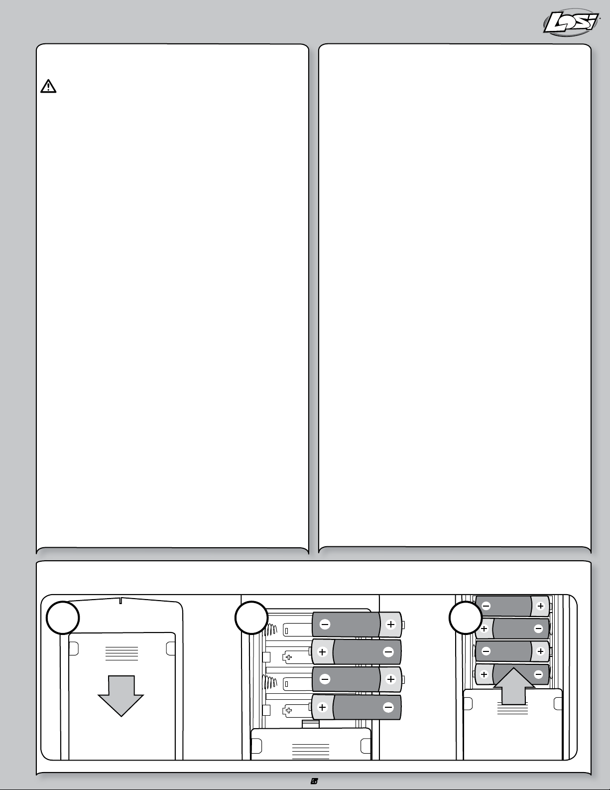
3. Install the AA batteries into the LSR-3000 Transmitter (see
page 5). Use alkaline or rechargeable batteries only.
4. Install a fully charged battery pack (see page 6).
5. Turn on the transmitter and then the vehicle. Always turn the
transmitter on before the vehicle and turn it off after the vehicle
has been turned off.
6. Check steering. Verify that the servo is functioning properly.
7. Driving the XXX-SCT (see page 7).
8. Performing maintenance of the XXX-SCT.
33
Page 4
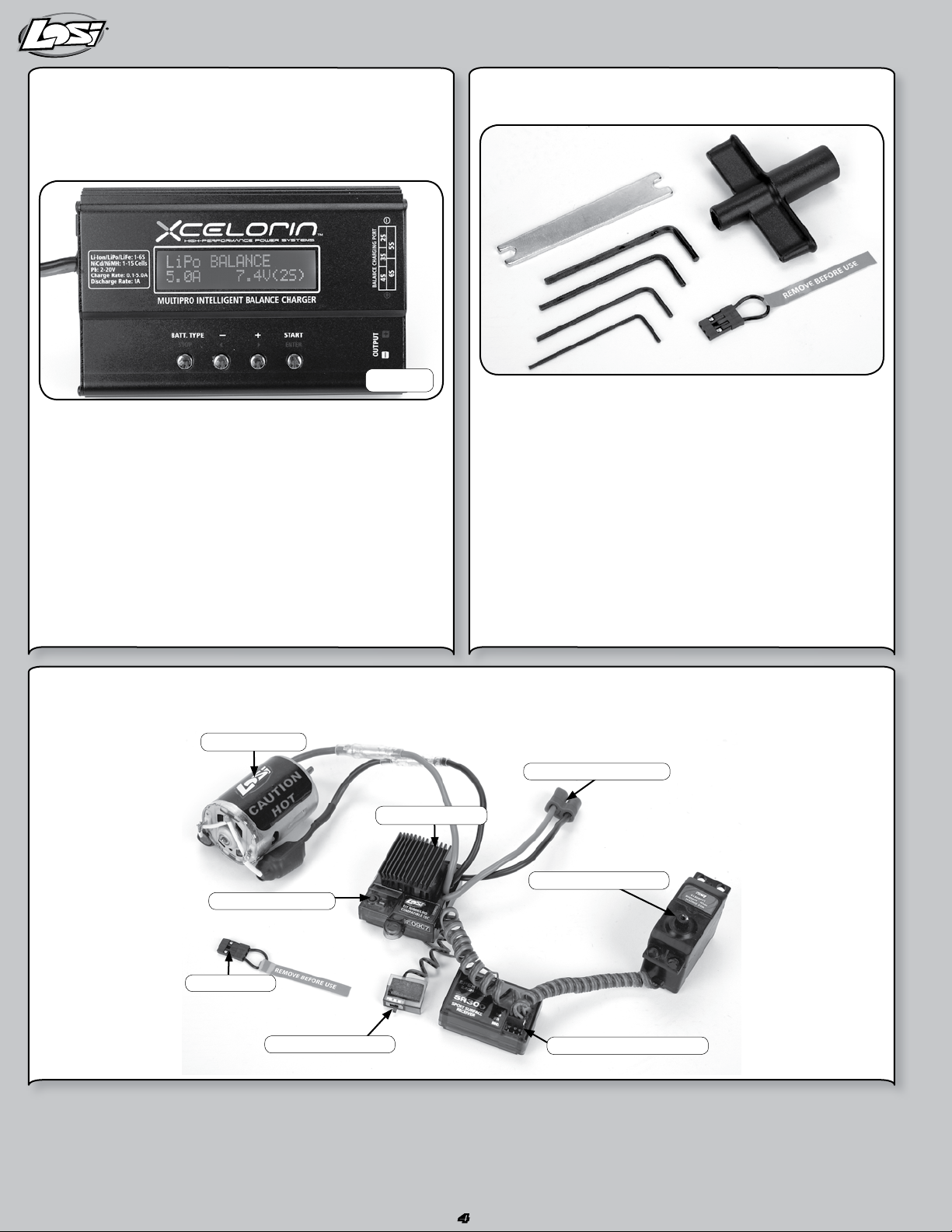
Peak detectioN charger
Peak detection chargers monitor the battery during charging and
automatically shut off upon full charge. You can either purchase a peak
detection charger that plugs into a household AC wall socket or one
that requires you to also purchase a 12V power supply.
suPPlied aNd reQuired eQuiPmeNt
Supplied tools
LOSB9602
If using a charger other than a peak detection charger, make sure your
battery is fully discharged prior to charging. Many of these have a
15–20 minute timer that allows you to set a charge time. If the battery
is not fully discharged, you can potentially over-charge your battery
pack. Do not charge any battery unattended, and monitor for heat
build up. If the battery pack is more than warm to the touch, immediately discontinue charging. Read all safety precautions supplied by the
charger and battery manufacturer.
XXX-sct electroNics system overview
LOSI MOTOR
LOSI MSC12L
2-Waywrench •Transmitter/ReceiverBINDPlug•
4HexWrench“L”shaped •.050,1/16,5/64,and3/32•
FlatTurnbuckleWrench •4AAAlkalineBatteries•
Recommended Accessories
Hobbygradeknife •Needlenosepliers•
Sidecuttingpliers •Safetygoggles•
Solderingiron •Double-sidedtape(LOSA4004)•
CA glue (LOSA7880 or LOSA7881)•
Required Equipment
A 6- to 7-cell NiMH battery pack. Or with proper knowledge, LiPo •
battery packs.
NiMH battery charger with automatic peak detection •
recommended (LiPo charger if using LiPo battery).
EC2™ BATTERY PLUG
SETUP BUTTON
BIND PLUG
ON/OFF SWITCH
STEERING SERVO
SPEKTRUM SPMSR300
44
Page 5
msc-12l fwd/rev esc
2 31
WARNING: This product can become extremely hot when in use,
which could lead to burns.
Features
LiPo, NiMH/NiCd compatible•
4 user selectable modes—Forward/reverse, Forward only •
race, Practice mode with slow acceleration, and Crawler.
High-power FET control with proportional forward and reverse.•
High frequency design delivers smooth speed transition.•
Thermal Overload Protection prevents damage due to over •
current conditions.
Pre-wired with EC3 battery plug and bullet-style motor connectors.•
Designed to operate with stock motors (12 turns or higher).•
Push-button programming with one touch setup.•
Water-resistant•
Specifications
Operation . . . . . . . . . . . . . . Proportional forward, proportional reverse
with braking delay
Input Voltage ............ 4-cell (4.8-volts) to 7-cell (8.4-volts)
DC NiMH/NiCd or 2S LiPo (7.4 volts)
Peak Current ............1000A Forward and 350A Backwards
Continuous Current .......250A Forward and 125A Backwards
Full-On Resistance . . . . . . . 0.0014 Ohms Forward
0.0028 Ohms Backwards
Frequency ..............1kHz
BEC output . . . . . . . . . . . . .5V DC, 1 amp max. at 7.2V
Overload Protection .......Thermal
Dimensions ............. 1.575 in x 1.575 in x 1.063 in
(40mm x 40mm x 27mm)
Weight . . . . . . . . . . . . . . . .1.87 oz (53 g)
Connecting the Battery
The MSC-12L comes pre-wired with an EC3 connector. Use battery
packs from 4-cell (4.8-volt) to 7-cell (8.4-volt) sub-C size battery packs
or with 2S LiPo packs (7.4-volt).
1. Be sure the on/off switch is in the “off” position.
2. Connect a fully charged battery pack to the speed control’s
battery connector.
Adjusting the Transmitter
1. Set the “throttle reversing” switch to the NORMAL position.
2. Set the “throttle trim” to the CENTER position.
Speed Control Programming
Note: While in the programming mode, no power is applied to
the motor.
Battery Selection: When the ESC is powered on, the LED will be
flashing for 2 seconds to indicate the Selected Battery Type. During this
time the user can press the key to toggle between LiPo and NiMH/NiCd
modes. After the key has been pressed (battery type selected), the LED
will flash for 2 more seconds.
A. Turn on ESC and push button once within 2 seconds, push again to
toggle between modes.
B. Red light indicates LiPo mode (with 6-volt cutoff).
C. Green light indicates NiMH/NiCd mode.
One-Touch Endpoint Setup
Note: Please be sure to set all throttle trim settings to neutral
before performing an endpoint setup.
A. Hold button and turn on ESC until the Red/Green light comes on.
Once on, release button.
B. Pull trigger to full throttle position until the green light goes from
flashing to solid. Once solid, your forward endpoint is now set.
C. To set reverse endpoint, push the trigger into the full reverse
position until the flashing red light turns solid. At this point your
reverse/brake endpoint is now set.
D. Return trigger to neutral setting. The green light will now be solid
and you are ready to go!
Selecting Speed Controller Modes
To change modes on your MSC-12L hold the setup key for over
5 seconds while in neutral. Once you find desired mode, simply release
the key and you are ready for action.
Forward/Reverse mode—Solid Green LED
Forward Only mode—Fast Flashing Green LED
Practice mode—Slow Flashing Green LED
Crawler mode*—Solid Green and Red LED
*NOTICE: Crawler mode is for use in rock crawling vehicles only.
Do not use this mode with your 1/10 XXX-SCT. Doing so
may damage the vehicle.
iNstalliNg the traNsmitter batteries
5
Page 6

iNstalliNg the battery Pack(s)
To install the battery pack, remove the battery hold-down strap by
removing the clip from the front mounting boss. Then, while lifting the
strap, pull forward in one motion.
After you have inserted the fully charged battery pack, reinstall the
battery hold-down strap.
The battery hold-down has a flat side while the other side has
strengthening ribs; the rib side should be face down to the battery.
Insert on an angle into the rear support, and then down on the front pin
and secure it with the previously removed clip.
losi lsr-3000 radio system
The XXX-SCT comes with the Losi LSR-3000 Radio System with
Spektrum™ 2.4GHz DSM® Technology. The system will not interfere
with radio systems operating on legacy frequencies such as 27MHz or
75MHz, neither will you experience any overlapping interference from
other 2.4GHz systems. The transmitter and receiver are bound together
from the factory to uniquely operate together.
Operation and Adjustment
ANTENNA
DUAL RATE ADJUSTMENT
(ST. D/R)
POWER
ON/OFF
STEERING
WHEEL
STEERING TRIM
(ST. TRIM)
THROTTLE TRIM
(TH. TRIM)
THROTTLE/
BRAKE TRIGGER
Power Switch – Turns the transmitter On and Off.•
Dual Rate – (ST.D/R) Adjusts how much the wheels can turn left/•
right in equal proportion.
Steering Trim – (ST.TRIM) Adjusts the “Hands Off” direction of the •
XXX-SCT.
Throttle Trim – (TH.TRIM) Fine adjustment for the throttle and •
brake center.
Receiver
There is no adjustment required of the receiver. Please note the
different slots for connection.
AUXILIARY CHANNEL
THROTTLE CHANNEL
STEERING CHANNEL
BIND PORT
There is Bind, channel one, channel two and auxiliary slots.
The bind slot is used to bind the transmitter to the receiver. The bind
process teaches the transmitter the unique GUID ID of the receiver.
Although the transmitter and receiver come bound, below are the steps
to rebind your transmitter and receiver should the need arise.
Rebind Process
1. Ensure the transmitter and vehicle are both turned off.
2. Using the supplied Bind plug (which looks like a standard receiver
plug with a short wire loop installed), insert the Bind plug into the
receiver slot labeled BIND.
Note: You do not need to remove any other plugs to rebind.
3. With the bind plug installed, turn on the vehicle. Notice the receiver
LED is now blinking.
4. Turn on the transmitter. You will see a similar blinking LED under a
translucent cover.
5. Both the receiver and transmitter LEDs will stop blinking and be on
solid, indicating they are bound.
66
Page 7

6. Turn off the vehicle and then the transmitter.
7. Remove the bind plug from the receiver.
8. Turn on the transmitter and then the vehicle to ensure
operation. If the transmitter does not control the vehicle, repeat
steps 1 –7 above. If after several attempts you are unsuccessful,
please contact Horizon product support.
Receiver Antenna
Using your fingers gently straighten the antenna wire to be close to
vertical from the chassis for the best radio reception.
Factory Settings of Radio/ESC
The Electronic Speed Control was calibrated together with the radio
system at the factory. When you turn on and run the XXX-SCT for the
first time, you may need to slightly adjust the Throttle Trim. If the vehicle
creeps in reverse or in forward, make a fine adjustment to the Throttle
Trim knob on the transmitter. Sometimes the bumps and bounces of
transportation can slightly alter the settings.
PrecautioNs for driviNg the XXX-sct
The Electronics in this vehicle are not waterproof. Avoid running •
the vehicle in or through standing water, wet grass, mud or snow.
This vehicle is quick:•
Do not run the vehicle if it will be out of sight for any amount of time.
Do not drive your vehicle near a crowd of people. Perform a check of the vehicle before going out to run it. Ensure the tires are not coming off the rims. Generally check the vehicle for items such as a loose wheel nut, or anything loose on the steering assembly. The vibrations
of running off-road tend to loosen screws and nuts.
The gearing of the XXX-SCT IS NOT meant for running the vehicle •
in tall grass.
Be careful driving when the battery is nearly discharged or the car •
is running slowly. You could lose enough power for the receiver to
shutdown and you may lose control.
When driving the XXX-SCT be cautious and use common sense.•
If your vehicle gets caught or stuck, do not pull the throttle in •
either forward or reverse. This will overload the ESC and/or motor
resulting in damage to one or possibly both.
After running a battery pack, allow the electronics several minutes •
to cool, before running the next battery pack.
Run Time
The single largest factor in run time is the mAh capacity of your battery
pack. The larger the mAh rating the more run time you will experience.
For example: if you have a 4600mAh battery pack, you can expect close
to twice the run time of a 2000mAh battery pack.
The condition of a battery pack is also an important factor in both run
time and speed. The longer you run, the hotter the battery plugs can
get. Check the standard plugs periodically. As batteries see more use
they will degrade in performance and capacity.
How you drive your XXX-SCT also affects your run times. If you are
performing runs, going from a standstill to full speed repeatedly, you
are taxing your batteries and electronics. Hard acceleration draws a lot
of current from any battery and will lead to shortened run time.
If the bearings are dirty, they will cause significant drag causing
reduced run times and speed.
To improve run times consider the following:
Keep your vehicle clean and maintained.•
Allow more airflow to the heat sink of the MSC 12RB ESC.•
Change the gearing to a lower ratio; this will make the •
electronics run cooler. To change gear ratio, use a smaller pinion
gear, or a larger spur gear than those originally supplied. (The XXXSCT comes with a 16- tooth pinion and an 88-tooth spur gear.)
Change to battery packs of higher mAh rating.•
Verify you are using the best charger for your batteries. (See your •
local hobby dealer.)
Tuning, Adjusting & Maintaining the XXX-SCT•
Periodically examine your XXX-SCT for the following:
Keep your vehicle clean using a brush to remove dirt and dust.•
Look for cracks in the suspension arms and other molded parts.•
Check that the tires are still glued to the wheels.•
Check that all the wheel bearings are clean and lubricated.•
Using your tools, attempt to tighten all the screws and nuts.•
Verify that the Camber Links and Steering Linkage are not bent.•
Check that the Toe and Camber settings are as desired and equal.•
Remove the gear cover.•
Check the Spur gear for wear. Check the Pinion gear. -
Check the Slipper Pads for wear. Take the shocks off the vehicle and check, especially if they •
appear to be leaking as it is time to rebuild them.
Look over all the wiring and connections for bare wire or any place •
which could lead to a short-circuit.
Verify the ESC is securely mounted to the chassis.•
Verify the receiver is still securely mounted to the chassis.•
Turn on the radio. If the Green LED is off or dim, replace the 4 AA •
batteries in the transmitter.
After you become familiar with driving your XXX-SCT, you may need to
reset or make adjustments to the alignment. Make sure to work on a
flat work space.
This will enable you to easily and more quickly make both Toe-in and
Camber adjustments. These adjustments should be set with the vehicle
sitting at its normal ride height.
7
Page 8

troubleshootiNg guide
Many questions are the result of simple user errors or minor
adjustments which are easily addressed. If after reading below you
cannot resolve your problem, contact the appropriate Horizon product
support center (see page 13).
Radio system does not work properly
If the power light on the transmitter is not turning on, first ensure
the batteries are installed correctly. You should also check that
the batteries are good and/or if rechargeable are fully charged.
Replace them if needed. If the power light is blinking, then the
transmitter batteries are weak and should be replaced. If the
transmitter light is on but the radio is still not responding, you may
need to rebind the transmitter to the receiver. Please see page 14.
Short radio range
If the radio range appears short, make sure the batteries are all
fully charged and/or are in good condition.
Steering works but the motor will not run
The speed control may have gotten too hot and thermally shut
down. Allow time for the speed control to cool. If this is the
problem and has happened a few times, consider using a smaller
pinion or a larger spur gear.
Check the transmission, do the rear wheels spin easily?
Check that a motor wire has not come loose.
Verify that the electronic speed control is plugged into the throttle
channel of the receiver.
Check using another battery. Contact Horizon support for service
instructions.
Steering servo does not work
Check all wires, radio system, battery connectors, and the
battery pack.
Contact Horizon support for service instructions.
Motor runs backwards
The Black wire lead from the motor should be connected to the
Black wire lead from the ESC and the same for the Red wires.
If not, please correct by swapping the wires. If you are still
experiencing problems, please contact Horizon support.
Motor starts running immediately after the battery has
been connected
There may be internal ESC damage. Contact Horizon customer
support.
Vehicle runs slowly/slow acceleration
Check battery connectors.
Confirm battery is charged.
Vehicle will not reverse
Make sure the throttle trim is at neutral.
Recalibrate/Setup the ESC (see page 9).
Check to see if the ESC is in Forward only mode that does not have
reverse active.
Keep stripping spur gears
Improper gear mesh, refer to page 19.
Improperly adjusted slipper, refer to page 18.
msc-12l fwd/rev esc troubleshootiNg guide
Symptom
Steering servo operates but the motor does not run
Steering and motor do not function
Full speed not attainable
Motor slows but will not stop
Reduced radio range/Interference
Solution
Programming is not complete. Reprogram the ESC by following the
programming instructions.
Speed control connected to receiver incorrectly.
Motor defective. Test motor independently, repair or replace as needed.
Low batteries. Charge as needed.
Overload Protection enabled. Check motor and connections.
Receiver wired incorrectly. Check polarity and orientation
of controlplugs.
Batteries discharged. Recharge or replace.
Transmitter adjusted improperly.
ESC programmed incorrectly. Reprogram.
Throttle trim may be set improperly.
ESC program does not match transmitter. Reprogram ESC.
Motor capacitors broken/missing. Repair or replace.
Motor noise. Move receiver further away from ESC, motor and wiring.
Transmitter batteries low. Replace batteries.
8
Page 9

rc termiNology
BEC (Battery Elimination Circuit)
BIND Process
Calibration
Current
Deadband
DSM
(Digital Spectrum Modulation)
ESC (Electronic Speed Control)
GUID
LiPo
mAh
Neutral Position
NiMH
Profiles
Receiver
Resistance
Servo An electronic device connected to the receiver used to actuate steering control of the vehicle.
Spektrum
Transmitter Is the device held in your hand that relays steering and throttle/brake requests made to the receiver.
Trim
Thermal Shutdown
The BEC eliminates the need for a receiver pack to power the radio system. On most electric vehicles
this is located in the electronic speed control (ESC), but can also be a stand-alone device.
Programming a receiver to recognize the GUID code of only one specific transmitter or
transmitter module.
Also called ESC setup. It is the process used to match the transmitter throttle, brake and neutral to the
ESC.
Refers to the power flow from the battery to the ESC and Motor when used in the RC vehicle
environment. Typically this is measured in Ampere or Amp.
This refers to the amount of travel (movement) on the transmitter trigger before the vehicle is
requesting the ESC to move the vehicle forward or backwards. It is an advanced adjustment used by
experienced drivers.
The 2.4GHz technology of Spektrum radios.
The ESC is what translates the signals past from the transmitter trigger through the receiver into
commands that reach the motor to signal forward or reverse, acceleration or braking. The Xcelorin
system is an advanced electronic speed controller that is very efficient in passing precise requests to
the brushless motor. The BEC is also controlled by the ESC along with the Low Voltage Protection circuit.
Globally Unique Identification Code. Each individual module or radio is factory programmed with its own
unique serial code. In the binding process, the receiver is programmed to only recognize the GUID code
of one specific radio or module.
A Lithium Polymer battery’s abbreviation indicating the chemistry used in these rechargeable
batteries. These batteries require special attention by the user and are only recommended for the most
experienced of users.
The Milliampere Hour abbreviation, which represents the capacity of a battery pack. The higher this
rating the longer the run time of each charge.
Referring to the Transmitter when at rest, meaning the throttle trigger and steering have no input. When
you turn the transmitter on, set it to the side while turning the car on, the transmitter will be in a Neutral
state.
The abbreviation for nickel-metal hydride rechargeable batteries. These have replaced the use of NiCd
batteries as the battery of choice in RC vehicles.
The MSC 12RB has two (2) preset profiles. Forward Only and Forward and Reverse profile. The Forward
only profile can be selected for racing purposes. The Forward/Reverse profile is great for running in
your neighborhood.
A device mounted into the vehicle that receives and decodes a signal sent by a transmitter. Servos, ESC
and other devices are plugged into the receiver.
As used here refers to the power loss from the battery to the ESC and Motor. Typically this is
measured in Ampere or Amp. Too much resistance between the battery, ESC and motor can result in
low performance and run time.
The technology brand of 2.4GHz radio system supplied with the XXX-SCT. The use of this technology
eliminates the concern of conflicting frequencies found with older legacy radio systems. It further
reduces to a minimum potential radio interference common with the legacy radio systems of the past.
This is a setting used on the transmitter to make fine adjustments to the steering or throttle/brake
trigger. For steering you would use the trim to make the adjustment for the vehicle to drive straight
without adding steering input to the transmitter.
Refers to the ESC operating temperature. The MSC 12RB ESC monitors its internal temperature and
will automatically prevent the ESC from delivering power to the motor, preventing damage due to
overheating the ESC’s electronics.
9
Page 10

rePlacemeNt Parts list
Part Number Description
LOSA1109 Front Shock Tower (XXX-T, XXX-NT)
LOSA1150 Front Outer Hinge Pin (XXX-T)
LOSA1610 Steering Hardware Set
LOSA1615 Short Ball Cups and Threaded Rod
LOSA1620 Steering/Servo Mount Assembly (XXX, XXX-T)
LOSA2006 Swivel Suspension Balls .250” (8)
LOSA2007 Hinge Pin 1.42” (XXT, XXX, XXX-T)
LOSA2103 Rear Shock Tower (XXX-SCT)
LOSA2108 Rear Pivot Plate (XXX, XXX-T)
LOSA2164 1/8” Upper Bulkhead / Outer Rear Hinge Pin (2)
LOSA2166 Inner Rear Hinge Pins (XXX, XXX-T)
LOSA2919 Gear Diff Transmission Case (Gear Diff only)
LOSA2930 Complete Diff Set
LOSA2931 Diff Gear Housing
LOSA2934 Steel Outdrives w/Pins (2) (DT, XXX-SCT)
LOSA2944 Motor Plate and Front Pin Brace (XXX-SCT)
LOSA3042 Gear Cover with Access Plug (XXX-SCT, XXX-T CR)
LOSA3060 Slipper Shaft, Spacer & Hardware
LOSA3066 Teflon® Assembly Lube
LOSA3075 Transmission Upper Gear, Idler, Shaft
LOSA3079 Idler Gear (2.19:1 and 2.43:1)
LOSA3123 Slipper Pad
LOSA3124 Slipper Spring, Cup, Spacer, Bushing, and Washer
LOSA3132 Slipper Backing Plate
LOSA3928 88T 48-Pitch Spur Gear
LOSA4004 Servo Tape (6)
LOSA4015 Foam Battery Block
LOS4116 48 Pitch Pinion Gear, 16T
LOSA4122 Front Kickplate, Bulkhead, and Steering Brace(XXX,T)
LOSA4125 Front Spindles/Carriers, and Rear Hubs (XXX-T)
LOSA4145 Front/4º Rear Pivot Block Set (XXX, XXX-T, XXX-SCT)
LOSA4132 Front Bumper, Motor Guard (Speed T, Desert -T
LOSA4136 Front and Rear Inner Pin Brace Set (XXX, XXX-T)
LOSA4224 Threaded Chassis Inserts - Short and Long
LOSA5015 Double O-Ring Shock Cartridge
LOSA5023 Spring Clamps & Cups (2)
LOSA5036 Front XXX-SCT Black Aluminum Shock Body
LOSA5037 Rear XXX-SCT Black Aluminum Shock Body
LOSA5045 Shock Pistons #56 (Red) (4)
LOSA5156 2.5” Spring 3.4 Rate Rear (Silver)
LOSA5150 2.5” Spring 2.3 Rate Rear (Pink)
LOSA5218 Team Losi Certified Shock Fluid 35 wt Front
LOSA6001 Ball Studs w/Rod Ends 4-40 x 3/16” (4)
LOSA6020 H.D. 30-degree Plastic Rod Ends (Sport) (12)
Part Number Description
LOSA6030 Assembly Wrench (version 2)
LOSA6044 H.D. Rod Ends & Balls: Desert-T, Speed-T 8B, 8T
LOSA6074 Adjustable L/R Turnbuckle Set (6) (Speed-T, Desert-T
LOSA6100 1/8” E-Clips
LOSA6102 C-clips, .1875” - Large (12)
LOSA6201 3mm x 8mm Cap-Head w/Washers (10)
LOSA6204 4-40 x 1/2” Cap-Head Screws (10)
LOSA6206 4-40 x 3/8” Cap-Head screws (10)
LOSA6210 4-40 x 3/8” Flat-Head Screws (10)
LOSA6215 #4 Narrow Washers (10)
LOSA6216 4-40 x 7/8” Cap-Head Screws (10)
LOSA6229 4-40 x 3/8” Button-Head Screws (10)
LOSA6230 Shim Assortment - 3/16”, 1/4”, 1/2” (20)
LOSA6233 4-40 x 5/8” Flat-Head Screws (10)
LOSA6300 4-40 Hex Nuts (10)
LOSA6303 10-32 Locknuts (4ea Nylon & Steel) (8)
LOSA6305 4-40 Aluminum Locknuts, Low Profile (10)
LOSA6306 4-40 Aluminum Mini Nuts (10)
LOSA6350 #4 and 1/8” Hardened Washers
LOSA6401 1/16” Pins for Wheels and Gears
LOSA6903 3/16” x 3/8” Teflon Sealed Bearings (2)
LOSA6908 1/2” x 3/4” Ball Bearings w/Teflon Seal (2)
LOSA6909 1/8” x 3/8” Ball Bearings (‘XX’ Trans) (2)
LOSA6954 5 X 10mm HD Clutch Bearings (2) 8B/8T, XXX-SCT
LOSB0805 LSR-3000 DSM Transmitter
LOSB0818 MSX Digital Servo, (HRL, DT, T, XXX-SCT)
LOSB2050 Front Suspension Arms (XXX-SCT)
LOSB2051 Rear Suspension Arms (XXX-SCT)
LOSB2406 XXX-SCT Front Bumper Set
LOSB2407 XXX-SCT Rear Bumper Set
LOSB2408 Nerf Gaurds, (XXX-SCT)
LOSB2409 Mud Flaps, XXX-SCT
LOSB2410 Main Chassis and Battery Brace (XXX-SCT)
LOSB2454 XXX-SCT Front & Rear Body Mount Set
LOSB3497 Wheel Hex Set
LOSB3573 Front Axles, XXX-SCT
LOSB3579 Constant Veloctiy Drive Shaft Set, (XXX-SCT)
LOSB7016 Front Wheels (pr) XXX-SCT
LOSB7017 Rear Wheels (pr) XXX-SCT
LOSB7215 Eclipse Tire XXX-SCT Tires (Blue) w/Foam (2)
LOSB8084 XXX-SCT ReadyLift Scheme
LOSB9522 MSC12L Forward/Reverse ESC, LiPo Cutoff
LOSB9999 1/10th LM-32K Motor
SPSMSR300 3-Channel DSM Sport Surface Receiver
10
Page 11

oPtioNal Parts list
Part Number Description
LOSA1126 Front Spindles & Carriers-VLA, XXX-T
LOSA2123 Rear Hub Carriers-VLA, XXXT
LOSA2961 CVD Rebuild Kit: XXX-SCT
LOSA2908 Monster Diff Square Spring/Setscrew
LOSA2911 One-Piece Diff Nut/Carrier
LOSA3018 Heavy-Duty Thrust Bearing Set
LOSA3033 Transmission Case & Spacers Set, XXX-T
LOSA3034 Transmission Screw Set, XXX-T
LOSA3036 2.43:1 Diff Gear, XXX
LOSA3038 Differential Half Outdrives Set, XXXCR
LOSA3039 Differential Drive Rings & Shims, XXXCR
LOSA3041 XXXCR Motor Plate
LOSA3042 Gear Cover & Plug, XXX
LOSA3043 XXXCR Gear Cover Plugs (4)
LOSA3065 Silicone Differential Compound (Optional)
LOSA3078 Diff Screw, Hardware & Seal Set
LOSA3927 90-Tooth, 48-Pitch Spur Gear for Double-Disk Slipper
LOSA3929 86-Tooth, 48-Pitch Spur Gear for Double-Disk Slipper
LOSA3930 84-Tooth, 48-Pitch Spur Gear for Double-Disk Slipper
LOS4112 48 Pitch Pinion Gear,12T
LOS4113 48 Pitch Pinion Gear,13T
LOS4114 48 Pitch Pinion Gear,14T
LOS4115 48 Pitch Pinion Gear,15T
LOS411 48 Pitch Pinion Gear,17T
LOS4118 48 Pitch Pinion Gear,18T
LOS4119 48 Pitch Pinion Gear,19T
LOS4120 48 Pitch Pinion Gear,20T
LOS4121 48 Pitch Pinion Gear,21T
LOSA4148 Front Pivot Block, Aluminum, All XXX
LOSA4149 Rear Pivot Block, Aluminum, XXX-T CR
LOSA5014 O-rings for shock cartridges
LOSA5043 Shock Pistons #60, Natural (4)
LOSA5046 Shock Pistons #56, Red (4)
LOSA5048 Shock Pistons #54, Blue (4)
LOSA5055 Threaded Shock Body Set, .9”
LOSA5056 Threaded Shock Body Set, 1.2”
LOSA5062 1.2” Titanium Nitride Shock Shaft
LOSA5064 1.0” Titanium Nitride Shock Shaft
LOSA5150 2.5” Spring 2.3 Rate, Pink
Part Number Description
LOSA5152 2.5” Spring 2.6 Rate, Red
LOSA5154 2.5” Spring 2.9 Rate, Orange
LOSA5156 2.5” Spring 3.4 Rate, Silver
LOSA5158 2.5” Spring 3.7 Rate, Green
LOSA5160 2.5” Spring 4.1 Rate, Blue
LOSA5222 Silicone Shock Oil, 20 wt
LOSA5213 Silicone Shock Oil, 22.5 wt
LOSA5223 Silicone Shock Oil, 25 wt
LOSA5214 Silicone Shock Oil, 27.5 wt
LOSA5224 Silicone Shock Oil, 30 wt
LOSA5215 Silicone Shock Oil, 32.5 wt
LOSA5225 Silicone Shock Oil, 35 wt
LOSA5216 Silicone Shock Oil,37.5 wt
LOSA5226 Silicone Shock Oil, 40 wt
LOSA5240 Shock Oil 6 Pk. 20, 25, 30, 35, 40, 45 wt
LOSA5242 Shock Oil 6 Pk. 17.5, 22.5, 27.5, 32.5, 37.5 wt
LOSA6907 5 X 8mm Ball Bearing
LOSA6912 3/32” x 3/16” Bearings for Steering (XX, XXT, XXX,T)
LOSA6951 Carbide Diff Balls, 3/32
LOSA9713 Graphite Kickplate, Bulkhead, & Steering Brace
LOSA9831 Graphite/Composite Rear Pivot Plate (XXX, XXX-T)
LOSA9722 Graphite Front Shock Tower, XXX-T
LOSA9822 Rear Shock Tower, Graphite, XXX-T
LOSA9930 Aluminum Upper Gear/Shaft 2.19:1, XXX-T
LOSA9940 Aluminum Hardcoated Suspension Balls
LOSB2132 Aluminum Rear VLA Hubs, 1 degree
LOSB2131 Aluminum Rear VLA Hubs, 0 degree
LOSB2133 Aluminum Front Spindles
LOSB2134 Aluminum Front Carriers
LOSB2225 Chassis Dirt Cover, XXX-SCT
LOSB2226 Rear Sway Bar, XXX-SCT
LOSB2227 Aluminum Battery Strap, XXX-SCT
LOSB3496 Aluminum 12mm Wheel Hexes
LOSB8087 XXX-SCT Clear Body
LOSB9606 MultiPro Intelligent Balance DC Charger
LOSB9861 7.4V 5000mAh 2-Cell LiPo, 20C
LOSB9862 7.4V 4400mAh 2-Cell LiPo, 30C
LOSB9868 7.4V 3600mAh 2-Cell LiPo, 20C
LOSB9873 7.4V 5000mAh 2-Cell LiPo, 40C
LOSB9900 7.2V 3800mAh 6-Cell Stick Pack
11
Page 12

warraNty aNd rePair Policy
Warranty Period: Exclusive Warranty- Horizon Hobby, Inc., (Horizon)
warranties that the Products purchased (the “Product”) will be free
from defects in materials and workmanship at the date of purchase by
the Purchaser.
Limited Warranty: Horizon reserves the right to change or modify
this warranty without notice and disclaims all other warranties,
express or implied.
(a) This warranty is limited to the original Purchaser (“Purchaser”) and
is not transferable. REPAIR OR REPLACEMENT AS PROVIDED UNDER
THIS WARRANTY IS THE EXCLUSIVE REMEDY OF THE PURCHASER. This
warranty covers only those Products purchased from an authorized
Horizon dealer. Third party transactions are not covered by this
warranty. Proof of purchase is required for all warranty claims.
(b) Limitations- HORIZON MAKES NO WARRANTY OR REPRESENTATION,
EXPRESS OR IMPLIED, ABOUT NON-INFRINGEMENT,
MERCHANTABILITY OR FITNESS FOR A PARTICULAR PURPOSE OF THE
PRODUCT. THE PURCHASER ACKNOWLEDGES THAT THEY ALONE HAVE
DETERMINED THAT THE PRODUCT WILL SUITABLY MEET THE
REQUIREMENTS OF THE PURCHASER’S INTENDED USE.
(c) Purchaser Remedy- Horizon’s sole obligation hereunder shall be that
Horizon will, at its option, (i) repair or (ii) replace, any Product
determined by Horizon to be defective. In the event of a defect, these
are the Purchaser’s exclusive remedies. Horizon reserves the right to
inspect any and all equipment involved in a warranty claim. Repair or
replacement decisions are at the sole discretion of Horizon. This
warranty does not cover cosmetic damage or damage due to acts of
God, accident, misuse, abuse, negligence, commercial use, or modification of or to any part of the Product. This warranty does not cover
damage due to improper installation, operation, maintenance, or
attempted repair by anyone other than Horizon. Return of any Product
by Purchaser must be approved in writing by Horizon before shipment.
Damage Limits: HORIZON SHALL NOT BE LIABLE FOR SPECIAL,
INDIRECT OR CONSEQUENTIAL DAMAGES, LOSS OF PROFITS OR
PRODUCTION OR COMMERCIAL LOSS IN ANY WAY CONNECTED WITH
THE PRODUCT, WHETHER SUCH CLAIM IS BASED IN CONTRACT,
WARRANTY, NEGLIGENCE, OR STRICT LIABILITY. Further, in no event
shall the liability of Horizon exceed the individual price of the Product
on which liability is asserted. As Horizon has no control over use, setup,
final assembly, modification or misuse, no liability shall be assumed nor
accepted for any resulting damage or injury. By the act of use, setup or
assembly, the user accepts all resulting liability.
If you as the Purchaser or user are not prepared to accept the
liability associated with the use of this Product, you are advised to
return this Product immediately in new and unused condition to the
place of purchase.
Law: These Terms are governed by Illinois law (without regard to
conflict of law principals).
WARRANTY SERVICES
Questions, Assistance, and Repairs: Your local hobby store and/or
place of purchase cannot provide warranty support or repair. Once
assembly, setup or use of the Product has been started, you must
contact Horizon directly. This will enable Horizon to better answer your
questions and service you in the event that you may need any
assistance. For questions or assistance, please direct your email to
productsupport@horizonhobby.com, or call 877.504.0233 toll free to
speak to a Product Support representative. You may also find
information on our website at www.horizonhobby.com.
Inspection or Repairs: If this Product needs to be inspected or
repaired, please use the Horizon Online Repair Request submission
process found on our website or call Horizon to obtain a Return
Merchandise Authorization (RMA) number. Pack the Product securely
using a shipping carton. Please note that original boxes may be
included, but are not designed to withstand the rigors of shipping
without additional protection. Ship via a carrier that provides tracking
and insurance for lost or damaged parcels, as Horizon is not responsible for merchandise until it arrives and is accepted at our facility. An
Online Repair Request is available at www.horizonhobby.com
http://www.horizonhobby.com under the Repairs tab. If you do not have
internet access, please contact Horizon Product Support to obtain a
RMA number along with instructions for submitting your product for
repair. When calling Horizon, you will be asked to provide your complete
name, street address, email address and phone number where you can
be reached during business hours. When sending product into Horizon,
please include your RMA number, a list of the included items, and a
brief summary of the problem. A copy of your original sales receipt
must be included for warranty consideration. Be sure your name,
address, and RMA number are clearly written on the outside of the
shipping carton.
Notice: Do not ship batteries to Horizon. If you have any issue
with a battery, please contact the appropriate Horizon Product
Support office.
Warranty Inspection and Repairs: To receive warranty service,
you must include your original sales receipt verifying the proof-ofpurchase date. Provided warranty conditions have been met,
your Product will be repaired or replaced free of charge. Repair or
replacement decisions are at the sole discretion of Horizon.
Non-Warranty Repairs: Should your repair not be covered by
warranty the repair will be completed and payment will be
required without notification or estimate of the expense unless
the expense exceeds 50% of the retail purchase cost. By submitting
the item for repair you are agreeing to payment of the repair without
notification. Repair estimates are available upon request. You must
include this request with your repair. Non-warranty repair estimates will
be billed a minimum of ½ hour of labor. In addition you will be billed for
return freight. Horizon accepts money orders and cashiers checks, as
well as Visa, MasterCard, American Express, and Discover cards.
By submitting any item to Horizon for inspection or repair, you are
agreeing to Horizon’s Terms and Conditions found on our website under
the Repairs tab.
12
Page 13

coNtact iNfo
Country of Purchase Horizon Hobby Address Phone Number/ Email
Horizon Service Center
(Electronics and engines)
United States of
America
United Kingdom Horizon Hobby Limited Units 1-4 Ployters Rd
Germany Horizon Technischer Service Hamburger Str. 10
France Horizon Hobby SAS 14 Rue Gustave Eiffel
Horizon Product Support
(All other products)
4105 Fieldstone Rd
Champaign, Illinois
61822 USA
4105 Fieldstone Rd
Champaign, Illinois
61822 USA
Staple Tye
Harlow, Essex
CM18 7NS
United Kingdom
25335 Elmshorn
Germany
Zone d’Activité du Réveil Matin
91230 Montgeron
877-504-0233
Online Repair Requests visit:
www.horizonhobby.com/repairs
877-504-0233
productsupport@horizonhobby.com
+44 (0) 1279 641 097
sales@horizonhobby.co.uk
+49 4121 46199 66
service@horizonhobby.de
+33 (0) 1 60 47 44 70
infofrance@horizonhobby.com
fcc statemeNt
This device complies with part 15 of the FCC rules. Operation is subject to the following two conditions: (1) This device may not cause harmful
interference, and (2) this device must accept any interference received, including interference that may cause undesired operation.
CAUTION: Changes or modifications not expressly approved by the party responsible for compliance could void the user’s authority to operate
the equipment.
This product contains a radio transmitter with wireless technology which has been tested and found to be compliant with the applicable regulations
governing a radio transmitter in the 2.400GHz to 2.4835GHz frequency range.
comPliaNce iNformatioN for the euroPeaN uNioN
Declaration of Conformity (in accordance with ISO/IEC
17050-1)
No. HH2010091701
Product(s): LOS 1/10 ReadyLift XXX-SCT RTR
Item Number(s): LOSB0106
Equipment class: 1
The object of declaration described above is in conformity with the
requirements of the specifications listed below, following the provisions
of the European R&TTE directive 1999/5/EC:
EN 300-328 Technical requirements for Radio equipment.
EN 301 489-1, General EMC requirements
301 489-17
EN 60950 Safety
Signed for and on behalf of:
Horizon Hobby, Inc.
Champaign, IL USA
September 17, 2010
Instructions for Disposal of WEEE by Users in the European Union
This product must not be disposed of with other waste. Instead, it is the user’s responsibility to dispose of their waste equipment by
handing it over to a designated collection point for the recycling of waste electrical and electronic equipment. The separate collection and
recycling of your waste equipment at the time of disposal will help to conserve natural resources and ensure that it is recycled in a
manner that protects human health and the environment. For more information about where you can drop off your waste equipment for recycling,
please contact your local city office, your household waste disposal service or where you purchased the product.
International Operations
and Risk Management
Steven A. Hall
Vice President
Horizon Hobby, Inc.
Declaration of Conformity (in accordance with ISO/IEC 17050-1)
No. HH2010091702
Product(s): LOS 1/10 ReadyLift XXX-SCT BND
Item Number(s): LOSB0106BD
Equipment class: 1
The object of declaration described above is in conformity with the
requirements of the specifications listed below, following the provisions
of the European R&TTE directive 1999/5/EC:
EN 301 489-1, General EMC requirements
301 489-17
Signed for and on behalf of:
Horizon Hobby, Inc.
Champaign, IL USA
September 17, 2010
International Operations
and Risk Management
Vice President
Horizon Hobby, Inc.
Steven A. Hall
13
Page 14

traNsmissioN eXPloded view
14
Page 15

LOSB3497
LOSB7017
LOSB7215
LOSB2051
LOSA6210
LOSA6210
LOSA6204
LOSA2006
LOSA5023
LOSA5015
LOSA5022
LOSA5037
LOSA6305
LOSA6206
LOSA5023
LOSA5013
LOSA6300
LOSB2454
LOSB2454
LOSA6204
LOSB2407
LOSA6100
LOSA2166
LOSA4136
LOSA6100
LOSA4145
LOSA2103
LOSA6216
LOSA6206
LOSA2407
LOSA6229
LOSA4132
LOSB3579
LOSA6903
LOSA9941
LOSA4125
LOSA6204
LOSA6704
LOSA6704
LOSB2409
LOSA6229
LOSA2108
LOSA6100
LOSA2164
rear eXPloded view
15
Page 16

LOSA1620
LOSA1620
LOSA1146
LOSA1610
LOSA1610
LOSA6954
LOSB7016
LOSB2050
LOSA6233
LOSA6210
LOSA2006
LOSB2406
LOSA5023
LOSA5015
LOSA5017
LOSB2406
LOSA6210
LOSA6299
LOSA6229
LOSA6074
LOSA6204
LOSA6020
LOSA6204
LOSA1150
LOSA6100
LOSA6204
LOSA6100
LOSA6074
LOSA2164
LOSB3573
LOSA4125
LOSA6306
LOSA6206
LOSA5023
LOSB2454
LOSA6306
LOSA6215
LOSA6001
LOSA6001
LOSA1620
LOSA6206
LOSA4122
LOSA4145
LOSA2944
LOSA6100
LOSA2007
LOSA1109
LOSA6306
LOSA1620
LOSA4122
LOSA6206
LOSA5036
LOSA6305
LOSA5013
LOSA6300
LOSA6210
froNt eXPloded view
16
Page 17

chassis eXPloded view
LOSB2410
LOSB2408
LOSA4224
LOSA6350
LOSA1620
LOSA1620
LOSA6001
LOSB2410
LOSA1615
LOSA4170
LOSB2410
LOSB2408
LOSA6204
LOSA4015
LOSA6206
17
Page 18

18
Page 19

19
Page 20

© 2010 Horizon Hobby, Inc.
Losi, EC2, Xcelorin and MultiPro are trademarks or registered trademarks of Horizon Hobby, Inc.
The Spektrum trademark is used with permission of Bachmann Industries, Inc.
Bullydog, Gear One, Geiser Bros., KC, Osiris, ReadyLift,Slednecks, and Yokahama are property of their respective owners and are used by permission or license by Horizon Hobby.
Teflon® is a trademark or registered trademark of E.I. DuPont de Nemours and Co. Corporation, Wilmington, Delaware.
Created 09/10 www.losi.com 800-0359
29279
 Loading...