

Page 1
INSTRUCTION MANUAL
BEDIENUNGSANLEITUNG
MANUEL D’UTILISATION
MANUALE DI ISTRUZIONI
Not responsible for errors. All prices subject to change without notice.
Page 2
NOTICE
All instructions, warranties and other collateral documents are subject to change at the sole discretion of Horizon Hobby, Inc. For up-to-date
product literature, visit www.horizonhobby.com and click on the support tab for this product.
Meaning of Special Language
The following terms are used throughout the product literature to indicate various levels of potential harm when operating this product:
NOTICE: Procedures, which if not properly followed, create a possibility of physical property damage AND a little or no possibility of injury.
CAUTION: Procedures, which if not properly followed, create the probability of physical property damage AND a possibility of serious injury.
WARNING: Procedures, which if not properly followed, create the probability of property damage, collateral damage, and serious injury OR create a
high probability of superficial injury.
WARNING: Read the ENTIRE instruction manual to become familiar with the features of the product before operating. Failure to operate the
product correctly can result in damage to the product, personal property and cause serious injury.
This is a sophisticated hobby product and NOT a toy. It must be operated with caution and common sense and requires some basic mechanical
ability. Failure to operate this Product in a safe and responsible manner could result in injury or damage to the product or other property. This
product is not intended for use by children without direct adult supervision. Do not attempt disassembly, use with incompatible components or
augment product in any way without the approval of Horizon Hobby, Inc. This manual contains instructions for safety, operation and maintenance. It
is essential to read and follow all the instructions and warnings in the manual, prior to assembly, setup or use, in order to operate correctly and avoid
damage or serious injury.
TABLE OF CONTENTS
Introduction . . . . . . . . . . . . . . . . . . . . . . . . . . . . . . . . . . . . . . . . . . . . . . . . . . . . . . . . . . . . . . . . . . . . . . . . . . . . . . . . . . . . . . . . . . . . . . . . . . . . . . . 3
Register your Losi Product Online . . . . . . . . . . . . . . . . . . . . . . . . . . . . . . . . . . . . . . . . . . . . . . . . . . . . . . . . . . . . . . . . . . . . . . . . . . . . . . . . . . . . . . . 3
Getting Ready ......................................................................................................3
Safety Precautions and Guidelines . . . . . . . . . . . . . . . . . . . . . . . . . . . . . . . . . . . . . . . . . . . . . . . . . . . . . . . . . . . . . . . . . . . . . . . . . . . . . . . . . . . . . . 3
Quick Start . . . . . . . . . . . . . . . . . . . . . . . . . . . . . . . . . . . . . . . . . . . . . . . . . . . . . . . . . . . . . . . . . . . . . . . . . . . . . . . . . . . . . . . . . . . . . . . . . . . . . . . . 3
Peak Detection Charger . . . . . . . . . . . . . . . . . . . . . . . . . . . . . . . . . . . . . . . . . . . . . . . . . . . . . . . . . . . . . . . . . . . . . . . . . . . . . . . . . . . . . . . . . . . . . . 4
Supplied and Required Equipment . . . . . . . . . . . . . . . . . . . . . . . . . . . . . . . . . . . . . . . . . . . . . . . . . . . . . . . . . . . . . . . . . . . . . . . . . . . . . . . . . . . . . . 4
XXX-SCT Electronics System Overview . . . . . . . . . . . . . . . . . . . . . . . . . . . . . . . . . . . . . . . . . . . . . . . . . . . . . . . . . . . . . . . . . . . . . . . . . . . . . . . . . . . 4
MSC-12L Fwd/Rev ESC ...............................................................................................5
Installing The Transmitter Batteries ......................................................................................5
Installing The Battery Pack(s) . . . . . . . . . . . . . . . . . . . . . . . . . . . . . . . . . . . . . . . . . . . . . . . . . . . . . . . . . . . . . . . . . . . . . . . . . . . . . . . . . . . . . . . . . . 6
Losi LSR-3000 Radio System . . . . . . . . . . . . . . . . . . . . . . . . . . . . . . . . . . . . . . . . . . . . . . . . . . . . . . . . . . . . . . . . . . . . . . . . . . . . . . . . . . . . . . . . . . 6
Precautions for Driving the XXX-SCT .....................................................................................7
Troubleshooting Guide . . . . . . . . . . . . . . . . . . . . . . . . . . . . . . . . . . . . . . . . . . . . . . . . . . . . . . . . . . . . . . . . . . . . . . . . . . . . . . . . . . . . . . . . . . . . . . . 8
RC Terminology .....................................................................................................9
Replacement Parts List ..............................................................................................10
Optional Parts List ..................................................................................................11
Warranty and Repair Policy ...........................................................................................12
Contact Info . . . . . . . . . . . . . . . . . . . . . . . . . . . . . . . . . . . . . . . . . . . . . . . . . . . . . . . . . . . . . . . . . . . . . . . . . . . . . . . . . . . . . . . . . . . . . . . . . . . . . . 13
FCC Statement . . . . . . . . . . . . . . . . . . . . . . . . . . . . . . . . . . . . . . . . . . . . . . . . . . . . . . . . . . . . . . . . . . . . . . . . . . . . . . . . . . . . . . . . . . . . . . . . . . . . 13
Compliance Information for the European Union . . . . . . . . . . . . . . . . . . . . . . . . . . . . . . . . . . . . . . . . . . . . . . . . . . . . . . . . . . . . . . . . . . . . . . . . . . . 13
Transmission Exploded View ..........................................................................................50
Rear Exploded View . . . . . . . . . . . . . . . . . . . . . . . . . . . . . . . . . . . . . . . . . . . . . . . . . . . . . . . . . . . . . . . . . . . . . . . . . . . . . . . . . . . . . . . . . . . . . . . . 51
Front Exploded View . . . . . . . . . . . . . . . . . . . . . . . . . . . . . . . . . . . . . . . . . . . . . . . . . . . . . . . . . . . . . . . . . . . . . . . . . . . . . . . . . . . . . . . . . . . . . . . . 52
Chassis Exploded View . . . . . . . . . . . . . . . . . . . . . . . . . . . . . . . . . . . . . . . . . . . . . . . . . . . . . . . . . . . . . . . . . . . . . . . . . . . . . . . . . . . . . . . . . . . . . . 53
Setup Sheets . . . . . . . . . . . . . . . . . . . . . . . . . . . . . . . . . . . . . . . . . . . . . . . . . . . . . . . . . . . . . . . . . . . . . . . . . . . . . . . . . . . . . . . . . . . . . . . . . . . . . 54
2
Page 3

3
INTRODUCTION
Thank you for purchasing the Losi® 1/10 XXX-SCT. We are confident
you will be satisfied with the performance of this durable and resilient
vehicle. Please read through the entire manual before setting up and
using your vehicle.
When setting your Electronic Speed Controller:•
Disconnect motor or remove the pinion gear during ESC setup or calibration functions.
Keep loose clothing, hair, gloves and fingers away from moving parts at all times.
REGISTER YOUR LOSI PRODUCT ONLINE
Register your XXX-SCT now and be the first to find out about the latest
option parts, product updates and more. Log on to www.LOSI.com and
follow the product registration link to stay connected.
GETTING READY
Thoroughly read all the enclosed material, precautions and follow
instructions to avoid damaging your new RC vehicle. If you choose to
not follow these steps or instructions, it will be considered negligence.
If after review of this manual and prior to running your XXX-SCT, you
determine this RC vehicle is not what you want—Do Not proceed and
Do Not run the XXX-SCT. If the XXX-SCT has been run, your local hobby
store will not be able to process a return or accept it for exchange.
SAFETY PRECAUTIONS AND GUIDELINES
Age Recommendation: Not for children under 14 years.
This is not a toy.
Always operate this RC model in a safe, reasonable and cautious
fashion. When driving the XXX-SCT avoid someone being hit by the
vehicle. You may cause serious injury to another person, or to personal
property should you make contact while running the XXX-SCT.
General
This RC Vehicle is not intended for use on public highways or •
roads.
Avoid areas that have many pedestrians or crowds of people.•
Keep in mind that this vehicle is radio controlled and can •
experience moments of radio loss or interference, provide for a
margin of error at all times.
Be aware that the motor and batteries of this RC vehicle will get •
HOT during each use. Be careful not to burn yourself.
Electronic Speed Control (ESC)
Read all safety precautions prior to each use.•
Never leave the vehicle/ESC unsupervised while it is switched on, •
in use or connected to a power source. If there is a short-circuit or
product defect, it could result in fire.
If there are exposed wires, do not use the ESC until you have •
installed shrink-wrap or replaced the wire.
Disconnect the battery from the ESC after use.•
The ESC is not waterproof and should not be exposed to moisture.•
Do not attempt to use 3-cell LiPo; doing so will damage the ESC •
and could result in fire.
Always turn on the transmitter first then the ESC to prevent an •
out-of-control vehicle.
Rubber tires can cause severe injury if there is a failure while running the vehicle while on a stand or when being held. Ensure rubber tires are securely mounted to the rims and if not,
re-glue them and check them often for security.
Batteries and Charging
The XXX-SCT uses rechargeable batteries such as NiMH. These
batteries all have special requirements to preserve performance
and last.
Read all instructions provided by the manufacturer of •
the batteries.
Never allow minors to charge battery packs.•
Always check to ensure the polarity of battery connection •
is correct.
Never leave batteries unattended while charging.•
Never charge a battery while it is installed in the XXX-SCT.•
Do not charge any battery that appears to have any damage.•
If there are exposed wires, do not charge or use the battery until •
you install shrink-wrap or replace the complete wire.
When charging NiMH batteries, select a charger to meet your
requirements. You need a charger that is a 100-240V wall charger or
one which requires a 12V power supply. Follow the charger
manufacturer’s instructions and precautions during each use.
QUICK START
Note: Please read the entire manual to gain a full understanding of
the XXX-SCT vehicle, fine-tuning the setup and performing
maintenance.
1. Read the safety precautions found on this page.
2. Charge the battery pack you have chosen (NOT INCLUDED).
Refer to the Manufacturer’s Supplied instructions for battery
charging information.
3. Install the AA batteries into the LSR-3000 Transmitter
(see page 5). Use alkaline or rechargeable batteries only.
4. Install a fully charged battery pack (see page 6).
5. Turn on the transmitter and then the vehicle. Always turn the
transmitter on before the vehicle and turn it off after the vehicle
has been turned off.
6. Check steering. Verify that the servo is functioning properly.
7. Driving the XXX-SCT (see page 7).
8. Performing maintenance of the XXX-SCT.
Page 4
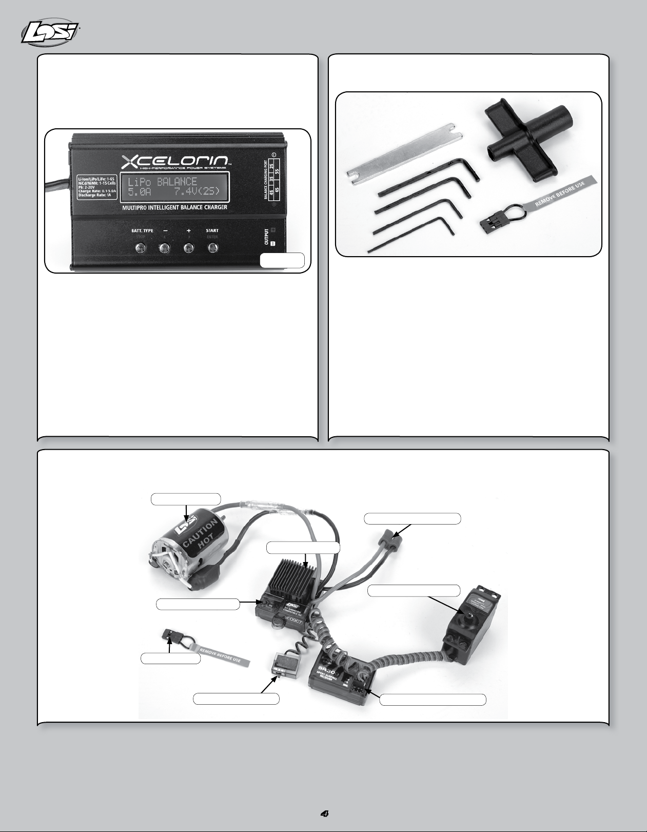
PEAK DETECTION CHARGER
Peak detection chargers monitor the battery during charging and
automatically shut off upon full charge. You can either purchase a peak
detection charger that plugs into a household AC wall socket or one
that requires you to also purchase a 12V power supply.
SUPPLIED AND REQUIRED EQUIPMENT
Supplied tools
LOSB9602
If using a charger other than a peak detection charger, make sure your
battery is fully discharged prior to charging. Many of these have a
15–20 minute timer that allows you to set a charge time. If the battery
is not fully discharged, you can potentially over-charge your battery
pack. Do not charge any battery unattended, and monitor for heat
build up. If the battery pack is more than warm to the touch, immediately discontinue charging. Read all safety precautions supplied by the
charger and battery manufacturer.
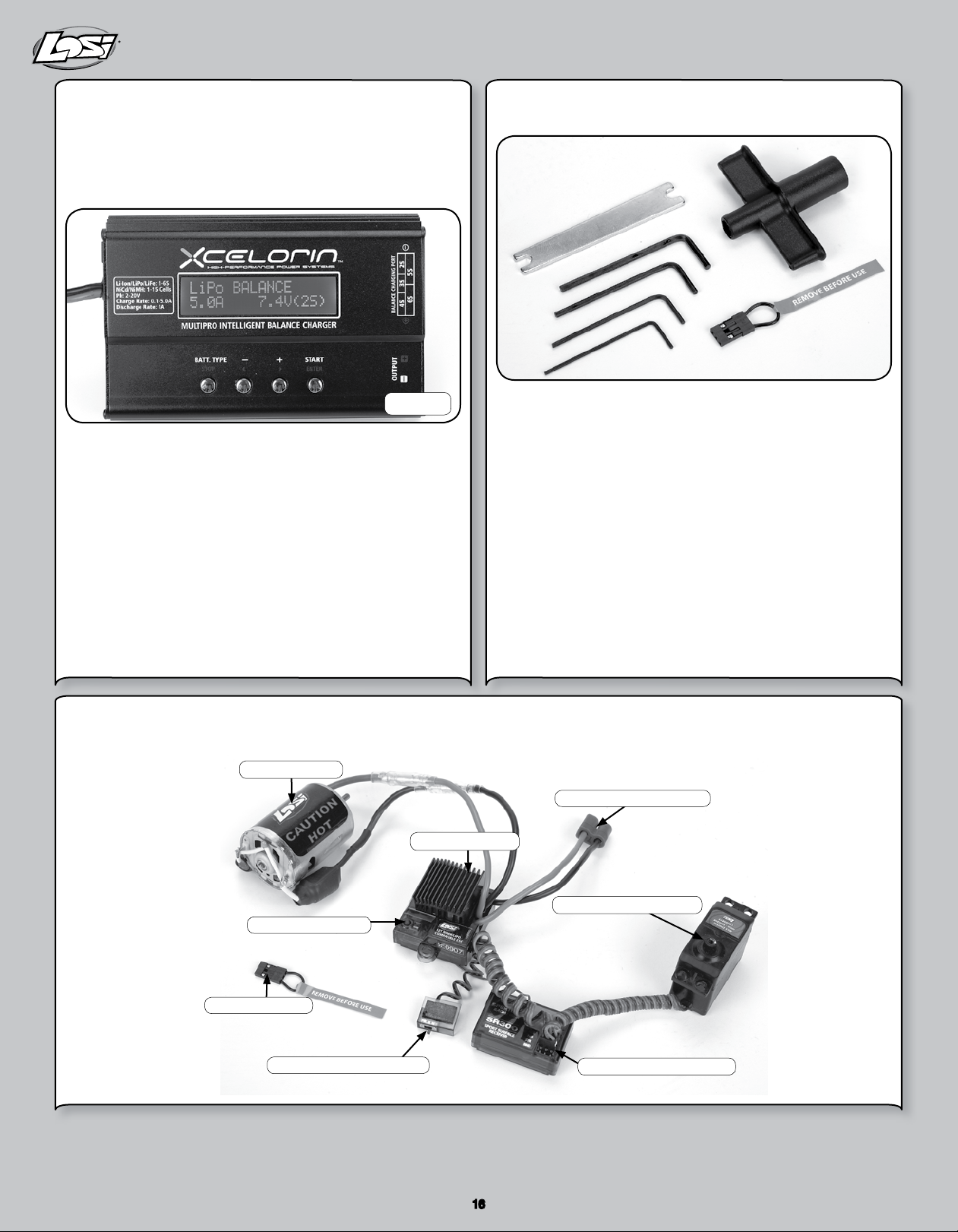
XXX-SCT ELECTRONICS SYSTEM OVERVIEW
LOSI MOTOR
LOSI MSC12L
2-Waywrench •Transmitter/ReceiverBINDPlug•
4HexWrench“L”shaped •.050,1/16,5/64,and3/32•
FlatTurnbuckleWrench •4AAAlkalineBatteries•
Recommended Accessories
Hobbygradeknife •Needlenosepliers•
Sidecuttingpliers •Safetygoggles•
Solderingiron •Double-sidedtape(LOSA4004)•
CA glue (LOSA7880 or LOSA7881)•
Required Equipment
A 6- to 7-cell NiMH battery pack. Or with proper knowledge, LiPo •
battery packs.
NiMH battery charger with automatic peak detection •
recommended (LiPo charger if using LiPo battery).
EC3™ BATTERY PLUG
SETUP BUTTON
BIND PLUG
ON/OFF SWITCH
STEERING SERVO
SPEKTRUM SPMSR300
4
Page 5
MSC-12L FWD/REV ESC
2 31
WARNING: This product can become extremely hot when in use,
which could lead to burns.
Features
LiPo, NiMH/NiCd compatible•
4 user selectable modes—Forward/reverse, Forward only •
race, Practice mode with slow acceleration, and Crawler.
High-power FET control with proportional forward and reverse.•
High frequency design delivers smooth speed transition.•
Thermal Overload Protection prevents damage due to over •
current conditions.
Pre-wired with EC3 battery plug and bullet-style motor connectors.•
Designed to operate with stock motors (12 turns or higher).•
Push-button programming with one touch setup.•
Water-resistant•
Specifications
Operation . . . . . . . . . . . . . . Proportional forward, proportional reverse
with braking delay
Input Voltage ............ 4-cell (4.8-volts) to 7-cell (8.4-volts)
DC NiMH/NiCd or 2S LiPo (7.4 volts)
Peak Current ............1000A Forward and 350A Backwards
Continuous Current .......250A Forward and 125A Backwards
Full-On Resistance . . . . . . . 0.0014 Ohms Forward
0.0028 Ohms Backwards
Frequency ..............1kHz
BEC output . . . . . . . . . . . . .5V DC, 1 amp max. at 7.2V
Overload Protection .......Thermal
Dimensions ............. 1.575 in x 1.575 in x 1.063 in
(40mm x 40mm x 27mm)
Weight . . . . . . . . . . . . . . . .1.87 oz (53 g)
Connecting the Battery
The MSC-12L comes pre-wired with an EC3 connector. Use battery
packs from 4-cell (4.8-volt) to 7-cell (8.4-volt) sub-C size battery packs
or with 2S LiPo packs (7.4-volt).
1. Be sure the on/off switch is in the “off” position.
2. Connect a fully charged battery pack to the speed control’s
battery connector.
Adjusting the Transmitter
1. Set the “throttle reversing” switch to the NORMAL position.
2. Set the “throttle trim” to the CENTER position.
Speed Control Programming
Note: While in the programming mode, no power is applied to
the motor.
Battery Selection: When the ESC is powered on, the LED will be
flashing for 2 seconds to indicate the Selected Battery Type. During this
time the user can press the key to toggle between LiPo and NiMH/NiCd
modes. After the key has been pressed (battery type selected), the LED
will flash for 2 more seconds.
A. Turn on ESC and push button once within 2 seconds, push again to
toggle between modes.
B. Red light indicates LiPo mode (with 6-volt cutoff).
C. Green light indicates NiMH/NiCd mode.
One-Touch Endpoint Setup
Note: Please be sure to set all throttle trim settings to neutral
before performing an endpoint setup.
A. Hold button and turn on ESC until the Red/Green light comes on.
Once on, release button.
B. Pull trigger to full throttle position until the green light goes from
flashing to solid. Once solid, your forward endpoint is now set.
C. To set reverse endpoint, push the trigger into the full reverse
position until the flashing red light turns solid. At this point your
reverse/brake endpoint is now set.
D. Return trigger to neutral setting. The green light will now be solid
and you are ready to go!
Selecting Speed Controller Modes
To change modes on your MSC-12L hold the setup key for over
5 seconds while in neutral. Once you find desired mode, simply release
the key and you are ready for action.
Forward/Reverse mode—Solid Green LED
Forward Only mode—Fast Flashing Green LED
Practice mode—Slow Flashing Green LED
Crawler mode*—Solid Green and Red LED
*NOTICE: Crawler mode is for use in rock crawling vehicles only.
Do not use this mode with your 1/10 XXX-SCT. Doing so
may damage the vehicle.
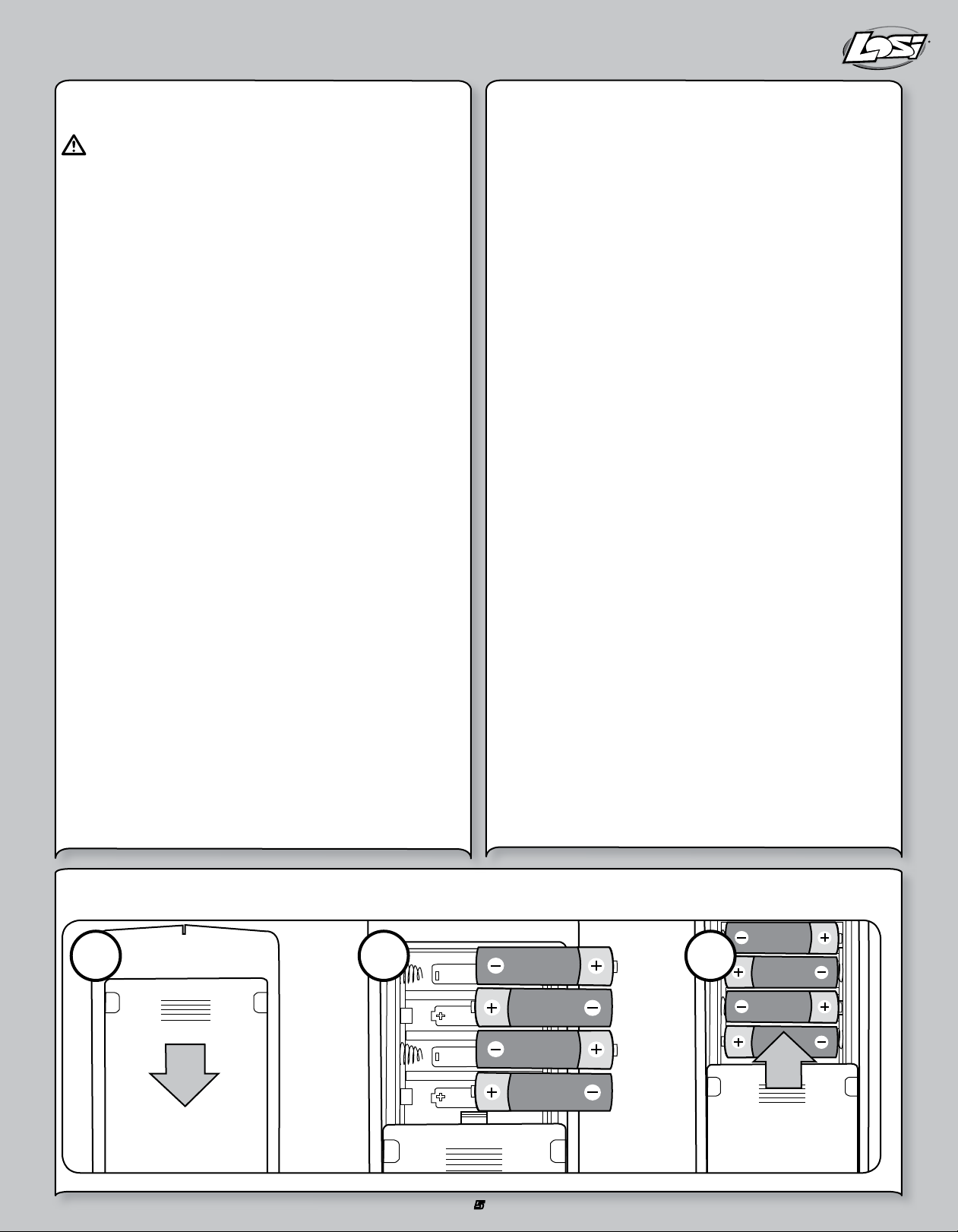
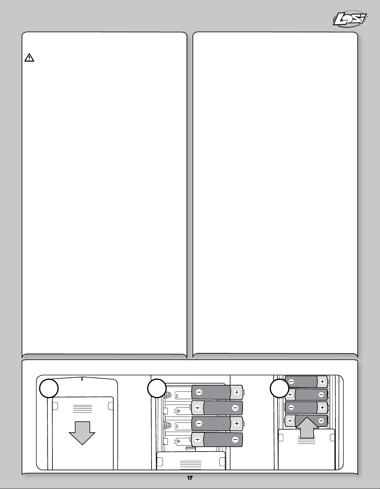
INSTALLING THE TRANSMITTER BATTERIES
5
Page 6
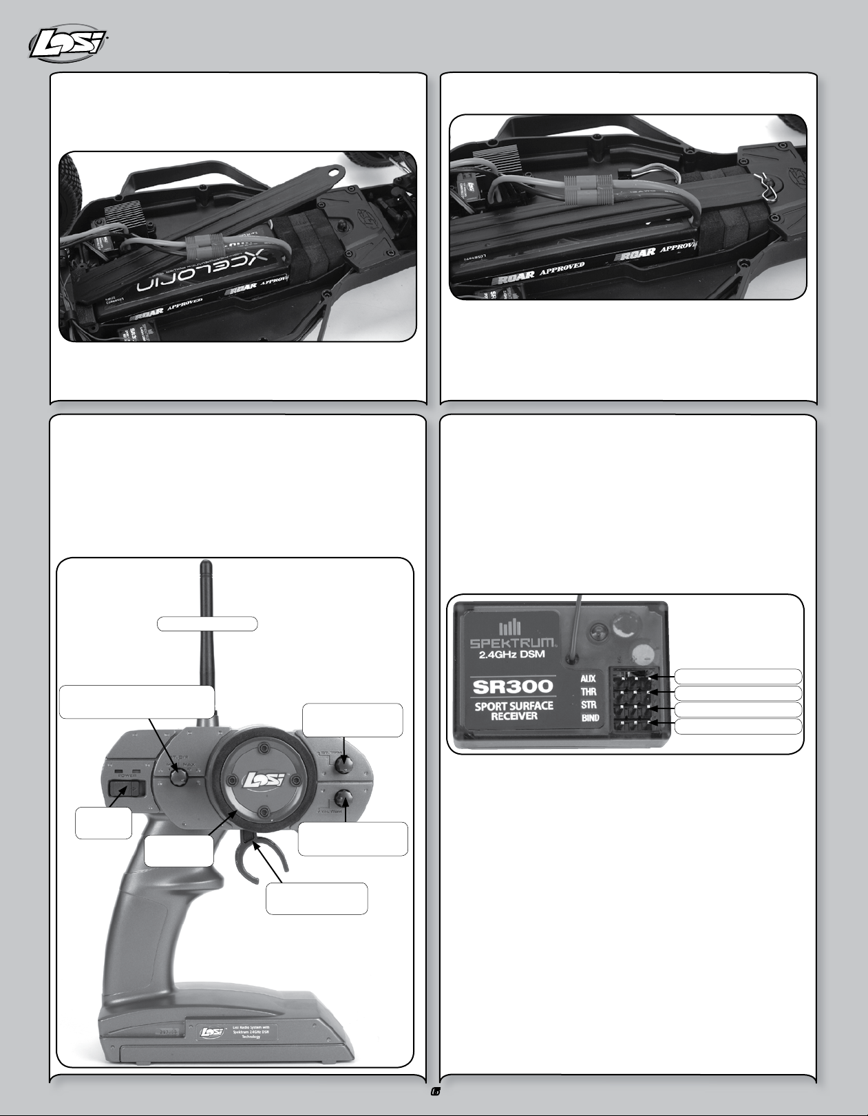
INSTALLING THE BATTERY PACK(S)
To install the battery pack, remove the battery hold-down strap by
removing the clip from the front mounting boss. Then, while lifting the
strap, pull forward in one motion.
After you have inserted the fully charged battery pack, reinstall the
battery hold-down strap.
The battery hold-down has a flat side while the other side has
strengthening ribs; the rib side should be face down to the battery.
Insert on an angle into the rear support, and then down on the front pin
and secure it with the previously removed clip.
LOSI LSR-3000 RADIO SYSTEM
The XXX-SCT comes with the Losi LSR-3000 Radio System with
Spektrum™ 2.4GHz DSM® Technology. The system will not interfere
with radio systems operating on legacy frequencies such as 27MHz or
75MHz, neither will you experience any overlapping interference from
other 2.4GHz systems. The transmitter and receiver are bound together
from the factory to uniquely operate together.
Operation and Adjustment
ANTENNA
DUAL RATE ADJUSTMENT
(ST. D/R)
POWER
ON/OFF
STEERING
WHEEL
STEERING TRIM
(ST. TRIM)
THROTTLE TRIM
(TH. TRIM)
THROTTLE/
BRAKE TRIGGER
Power Switch – Turns the transmitter On and Off.•
Dual Rate – (ST.D/R) Adjusts how much the wheels can turn left/•
right in equal proportion.
Steering Trim – (ST.TRIM) Adjusts the “Hands Off” direction of the •
XXX-SCT.
Throttle Trim – (TH.TRIM) Fine adjustment for the throttle and •
brake center.
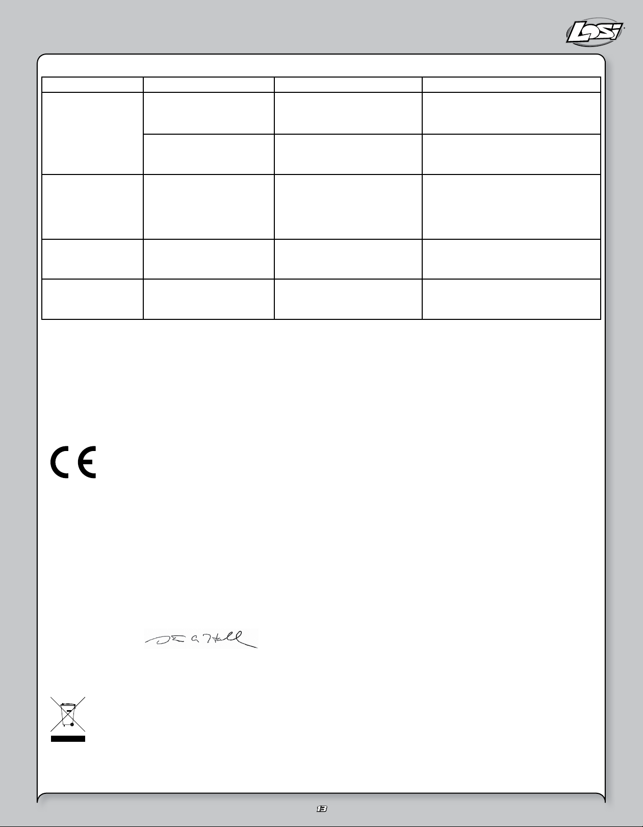
Receiver
There is no adjustment required of the receiver. Please note the
different slots for connection.
AUXILIARY CHANNEL
THROTTLE CHANNEL
STEERING CHANNEL
BIND PORT
There is Bind, channel one, channel two and auxiliary slots.
The bind slot is used to bind the transmitter to the receiver. The bind
process teaches the transmitter the unique GUID ID of the receiver.
Although the transmitter and receiver come bound, below are the steps
to rebind your transmitter and receiver should the need arise.
Rebind Process
1. Ensure the transmitter and vehicle are both turned off.
2. Using the supplied Bind plug (which looks like a standard receiver
plug with a short wire loop installed), insert the Bind plug into the
receiver slot labeled BIND.
Note: You do not need to remove any other plugs to rebind.
3. With the bind plug installed, turn on the vehicle. Notice the receiver
LED is now blinking.
4. Turn on the transmitter. You will see a similar blinking LED under a
translucent cover.
5. Both the receiver and transmitter LEDs will stop blinking and be on
solid, indicating they are bound.
6
Page 7

7
6. Turn off the vehicle and then the transmitter.
7. Remove the bind plug from the receiver.
8. Turn on the transmitter and then the vehicle to ensure
operation. If the transmitter does not control the vehicle, repeat
steps 1 –7 above. If after several attempts you are unsuccessful,
please contact Horizon product support.
Receiver Antenna
Using your fingers gently straighten the antenna wire to be close to
vertical from the chassis for the best radio reception.
Factory Settings of Radio/ESC
The Electronic Speed Control was calibrated together with the radio
system at the factory. When you turn on and run the XXX-SCT for the
first time, you may need to slightly adjust the Throttle Trim. If the vehicle
creeps in reverse or in forward, make a fine adjustment to the Throttle
Trim knob on the transmitter. Sometimes the bumps and bounces of
transportation can slightly alter the settings.
PRECAUTIONS FOR DRIVING THE XXX-SCT
The Electronics in this vehicle are not waterproof. Avoid running •
the vehicle in or through standing water, wet grass, mud or snow.
This vehicle is quick:•
Do not run the vehicle if it will be out of sight for any amount of time.
Do not drive your vehicle near a crowd of people. Perform a check of the vehicle before going out to run it. Ensure the tires are not coming off the rims. Generally check the vehicle for items such as a loose wheel nut, or anything loose on the steering assembly. The vibrations
of running off-road tend to loosen screws and nuts.
The gearing of the XXX-SCT IS NOT meant for running the vehicle •
in tall grass.
Be careful driving when the battery is nearly discharged or the car •
is running slowly. You could lose enough power for the receiver to
shutdown and you may lose control.
When driving the XXX-SCT be cautious and use common sense.•
If your vehicle gets caught or stuck, do not pull the throttle in •
either forward or reverse. This will overload the ESC and/or motor
resulting in damage to one or possibly both.
After running a battery pack, allow the electronics several minutes •
to cool, before running the next battery pack.
Run Time
The single largest factor in run time is the mAh capacity of your battery
pack. The larger the mAh rating the more run time you will experience.
For example: if you have a 4600mAh battery pack, you can expect close
to twice the run time of a 2000mAh battery pack.
The condition of a battery pack is also an important factor in both run
time and speed. The longer you run, the hotter the battery plugs can
get. Check the standard plugs periodically. As batteries see more use
they will degrade in performance and capacity.
How you drive your XXX-SCT also affects your run times. If you are
performing runs, going from a standstill to full speed repeatedly, you
are taxing your batteries and electronics. Hard acceleration draws a lot
of current from any battery and will lead to shortened run time.
If the bearings are dirty, they will cause significant drag causing
reduced run times and speed.
To improve run times consider the following:
Keep your vehicle clean and maintained.•
Allow more airflow to the heat sink of the MSC 12RB ESC.•
Change the gearing to a lower ratio; this will make the •
electronics run cooler. To change gear ratio, use a smaller pinion
gear, or a larger spur gear than those originally supplied. (The XXXSCT comes with a 16- tooth pinion and an 88-tooth spur gear.)
Change to battery packs of higher mAh rating.•
Verify you are using the best charger for your batteries. (See your •
local hobby dealer.)
Tuning, Adjusting & Maintaining the XXX-SCT•
Periodically examine your XXX-SCT for the following:
Keep your vehicle clean using a brush to remove dirt and dust.•
Look for cracks in the suspension arms and other molded parts.•
Check that the tires are still glued to the wheels.•
Check that all the wheel bearings are clean and lubricated.•
Using your tools, attempt to tighten all the screws and nuts.•
Verify that the Camber Links and Steering Linkage are not bent.•
Check that the Toe and Camber settings are as desired and equal.•
Remove the gear cover.•
Check the Spur gear for wear. Check the Pinion gear. -
Check the Slipper Pads for wear. Take the shocks off the vehicle and check, especially if they •
appear to be leaking as it is time to rebuild them.
Look over all the wiring and connections for bare wire or any place •
which could lead to a short-circuit.
Verify the ESC is securely mounted to the chassis.•
Verify the receiver is still securely mounted to the chassis.•
Turn on the radio. If the Green LED is off or dim, replace the 4 AA •
batteries in the transmitter.
After you become familiar with driving your XXX-SCT, you may need to
reset or make adjustments to the alignment. Make sure to work on a
flat work space.
This will enable you to easily and more quickly make both Toe-in and
Camber adjustments. These adjustments should be set with the vehicle
sitting at its normal ride height.
Page 8

TROUBLESHOOTING GUIDE
Many questions are the result of simple user errors or minor
adjustments which are easily addressed. If after reading below you
cannot resolve your problem, contact the appropriate Horizon product
support center (see page 13).
Radio system does not work properly
If the power light on the transmitter is not turning on, first ensure
the batteries are installed correctly. You should also check that
the batteries are good and/or if rechargeable are fully charged.
Replace them if needed. If the power light is blinking, then the
transmitter batteries are weak and should be replaced. If the
transmitter light is on but the radio is still not responding, you may
need to rebind the transmitter to the receiver. Please see page 6.
Short radio range
If the radio range appears short, make sure the batteries are all
fully charged and/or are in good condition.
Steering works but the motor will not run
The speed control may have gotten too hot and thermally shut
down. Allow time for the speed control to cool. If this is the
problem and has happened a few times, consider using a smaller
pinion or a larger spur gear.
Check the transmission, do the rear wheels spin easily?
Check that a motor wire has not come loose.
Verify that the electronic speed control is plugged into the throttle
channel of the receiver.
Check using another battery. Contact Horizon support for service
instructions.
Steering servo does not work
Check all wires, radio system, battery connectors, and the
battery pack.
Contact Horizon support for service instructions.
Motor runs backwards
The Black wire lead from the motor should be connected to the
Black wire lead from the ESC and the same for the Red wires.
If not, please correct by swapping the wires. If you are still
experiencing problems, please contact Horizon support.
Motor starts running immediately after the battery has
been connected
There may be internal ESC damage. Contact Horizon customer
support.
Vehicle runs slowly/slow acceleration
Check battery connectors.
Confirm battery is charged.
Vehicle will not reverse
Make sure the throttle trim is at neutral.
Recalibrate/Setup the ESC (see page 5).
Check to see if the ESC is in Forward only mode that does
not have reverse active.
Keep stripping spur gears
Improper gear mesh: Make sure mesh engages all teeth but
is not too tight causing binding.
Improperly adjusted slipper: Slipper should slip for first 1-2 feet.
If it is too tight, loosen. If too loose tighten and re-check.
MSC-12L FWD/REV ESC TROUBLESHOOTING GUIDE
Symptom
Steering servo operates but the motor does not run
Steering and motor do not function
Full speed not attainable
Motor slows but will not stop
Reduced radio range/Interference
Solution
Programming is not complete. Reprogram the ESC by following the
programming instructions.
Speed control connected to receiver incorrectly.
Motor defective. Test motor independently, repair or replace as needed.
Low batteries. Charge as needed.
Overload Protection enabled. Check motor and connections.
Receiver wired incorrectly. Check polarity and orientation
of controlplugs.
Batteries discharged. Recharge or replace.
Transmitter adjusted improperly.
ESC programmed incorrectly. Reprogram.
Throttle trim may be set improperly.
ESC program does not match transmitter. Reprogram ESC.
Motor capacitors broken/missing. Repair or replace.
Motor noise. Move receiver further away from ESC, motor and wiring.
Transmitter batteries low. Replace batteries.
8
Page 9

RC TERMINOLOGY
BEC (Battery Elimination Circuit)
BIND Process
Calibration
Current
Deadband
DSM
(Digital Spectrum Modulation)
ESC (Electronic Speed Control)
GUID
LiPo
mAh
Neutral Position
NiMH
Profiles
Receiver
Resistance
Servo An electronic device connected to the receiver used to actuate steering control of the vehicle.
Spektrum
Transmitter Is the device held in your hand that relays steering and throttle/brake requests made to the receiver.
Trim
Thermal Shutdown
The BEC eliminates the need for a receiver pack to power the radio system. On most electric vehicles
this is located in the electronic speed control (ESC), but can also be a stand-alone device.
Programming a receiver to recognize the GUID code of only one specific transmitter or
transmitter module.
Also called ESC setup. It is the process used to match the transmitter throttle, brake and neutral to the
ESC.
Refers to the power flow from the battery to the ESC and Motor when used in the RC vehicle
environment. Typically this is measured in Ampere or Amp.
This refers to the amount of travel (movement) on the transmitter trigger before the vehicle is
requesting the ESC to move the vehicle forward or backwards. It is an advanced adjustment used by
experienced drivers.
The 2.4GHz technology of Spektrum radios.
The ESC is what translates the signals passed from the transmitter trigger through the receiver into
commands that reach the motor to signal forward or reverse, acceleration or braking. The Xcelorin
system is an advanced electronic speed controller that is very efficient in passing precise requests to
the brushless motor. The BEC is also controlled by the ESC along with the Low Voltage Protection circuit.
Globally Unique Identification Code. Each individual module or radio is factory programmed with its own
unique serial code. In the binding process, the receiver is programmed to only recognize the GUID code
of one specific radio or module.
A Lithium Polymer battery’s abbreviation indicating the chemistry used in these rechargeable
batteries. These batteries require special attention by the user and are only recommended for the most
experienced of users.
The Milliampere Hour abbreviation, which represents the capacity of a battery pack. The higher this
rating the longer the run time of each charge.
Referring to the Transmitter when at rest, meaning the throttle trigger and steering have no input. When
you turn the transmitter on, set it to the side while turning the car on, the transmitter will be in a Neutral
state.
The abbreviation for nickel-metal hydride rechargeable batteries. These have replaced the use of NiCd
batteries as the battery of choice in RC vehicles.
The MSC 12RB has two (2) preset profiles. Forward Only and Forward and Reverse profile. The Forward
only profile can be selected for racing purposes. The Forward/Reverse profile is great for running in
your neighborhood.
A device mounted into the vehicle that receives and decodes a signal sent by a transmitter. Servos, ESC
and other devices are plugged into the receiver.
As used here refers to the power loss from the battery to the ESC and Motor. Typically this is
measured in Ampere or Amp. Too much resistance between the battery, ESC and motor can result in
low performance and run time.
The technology brand of 2.4GHz radio system supplied with the XXX-SCT. The use of this technology
eliminates the concern of conflicting frequencies found with older legacy radio systems. It further
reduces to a minimum potential radio interference common with the legacy radio systems of the past.
This is a setting used on the transmitter to make fine adjustments to the steering or throttle/brake
trigger. For steering you would use the trim to make the adjustment for the vehicle to drive straight
without adding steering input to the transmitter.
Refers to the ESC operating temperature. The MSC 12RB ESC monitors its internal temperature and
will automatically prevent the ESC from delivering power to the motor, preventing damage due to
overheating the ESC’s electronics.
9
Page 10

10
REPLACEMENT PARTS LIST
Part Number Description
LOSA1109 Front Shock Tower (XXX-T, XXX-NT)
LOSA1150 Front Outer Hinge Pin (XXX-T)
LOSA1610 Steering Hardware Set
LOSA1615 Short Ball Cups and Threaded Rod
LOSA1620 Steering/Servo Mount Assembly (XXX, XXX-T)
LOSA2006 Swivel Suspension Balls .250” (8)
LOSA2007 Hinge Pin 1.42” (XXT, XXX, XXX-T)
LOSA2103 Rear Shock Tower (XXX-SCT)
LOSA2164 1/8” Upper Bulkhead / Outer Rear Hinge Pin (2)
LOSA2166 Inner Rear Hinge Pins (XXX, XXX-T)
LOSA2919 Gear Diff Transmission Case (Gear Diff only)
LOSA2930 Complete Diff Set
LOSA2931 Diff Gear Housing
LOSA2934 Steel Outdrives w/Pins (2) (DT, XXX-SCT)
LOSA2944 Motor Plate and Front Pin Brace (XXX-SCT)
LOSA3034 Transmission Screw Set
LOSA3042 Gear Cover with Access Plug (XXX-SCT, XXX-T CR)
LOSA3060 Slipper Shaft, Spacer & Hardware
LOSA3066 Teflon® Assembly Lube
LOSA3075 Transmission Upper Gear, Idler, Shaft
LOSA3079 Idler Gear (2.19:1 and 2.43:1)
LOSA3123 Slipper Pad
LOSA3124 Slipper Spring, Cup, Spacer, Bushing, and Washer
LOSA3132 Slipper Backing Plate
LOSA3928 88T 48-Pitch Spur Gear
LOSA4004 Servo Tape (6)
LOSA4015 Foam Battery Block
LOS4116 48 Pitch Pinion Gear, 16T
LOSA4122 Front Kickplate, Bulkhead, and Steering Brace(XXX,T)
LOSA4125 Front Spindles/Carriers, and Rear Hubs (XXX-T)
LOSA4145 Front/4º Rear Pivot Block Set (XXX, XXX-T, XXX-SCT)
LOSA4132 Front Bumper, Motor Guard (Speed T, Desert -T
LOSA4136 Front and Rear Inner Pin Brace Set (XXX, XXX-T)
LOSA4146 Rear Pivot Plate (XXX, XXX-T)
LOSA4224 Threaded Chassis Inserts - Short and Long
LOSA5013 Shock Mount Bushings
LOSA5015 Double O-Ring Shock Cartridge
LOSA5017 1.0” Shock Shaft
LOSA5022 Shock Shaft 1.2”
LOSA5023 Spring Clamps & Cups (2)
LOSA5036 Front XXX-SCT Black Aluminum Shock Body
LOSA5037 Rear XXX-SCT Black Aluminum Shock Body
LOSA5046 Shock Pistons #56 (Red) (4)
LOSA5156 2.5” Spring 3.4 Rate Rear (Silver)
LOSA5150 2.5” Spring 2.3 Rate Rear (Pink)
LOSA5218 Team Losi Certified Shock Fluid 35 wt Front
LOSA6001 Ball Studs w/Rod Ends 4-40 x 3/16” (4)
LOSA6020 H.D. 30-degree Plastic Rod Ends (Sport) (12)
Part Number Description
LOSA6030 Assembly Wrench (version 2)
LOSA6044 H.D. Rod Ends & Balls: Desert-T, Speed-T 8B, 8T
LOSA6074 Adjustable L/R Turnbuckle Set (6) (Speed-T, Desert-T
LOSA6100 1/8” E-Clips
LOSA6102 C-clips, .1875” - Large (12)
LOSA6201 3mm x 8mm Cap-Head w/Washers (10)
LOSA6204 4-40 x 1/2” Cap-Head Screws (10)
LOSA6206 4-40 x 3/8” Cap-Head screws (10)
LOSA6210 4-40 x 3/8” Flat-Head Screws (10)
LOSA6215 #4 Narrow Washers (10)
LOSA6216 4-40 x 7/8” Cap-Head Screws (10)
LOSA6221 4-40 x 5/8” Cap Screws
LOSA6226 Flat Head Screw, 4-40 x 7/8”
LOSA6229 4-40 x 3/8” Button-Head Screws (10)
LOSA6230 Shim Assortment - 3/16”, 1/4”, 1/2” (20)
LOSA6233 4-40 x 5/8” Flat-Head Screws (10)
LOSA6300 4-40 Hex Nuts (10)
LOSA6303 10-32 Locknuts (4ea Nylon & Steel) (8)
LOSA6305 4-40 Aluminum Locknuts, Low Profile (10)
LOSA6306 4-40 Aluminum Mini Nuts (10)
LOSA6350 #4 and 1/8” Hardened Washers
LOSA6401 1/16” Pins for Wheels and Gears
LOSA6903 3/16” x 3/8” Teflon Sealed Bearings (2)
LOSA6908 1/2” x 3/4” Ball Bearings w/Teflon Seal (2)
LOSA6909 1/8” x 3/8” Ball Bearings (‘XX’ Trans) (2)
LOSA6954 5 X 10mm HD Clutch Bearings (2) 8B/8T, XXX-SCT
LOSA7215 Eclipse Tire XXX-SCT Tires (Blue) w/Foam (2)
LOSA8200 Body Clips
LOSB0805 LSR-3000 DSM Transmitter
LOSB0818 MSX Digital Servo, (HRL, DT, T, XXX-SCT)
LOSB2050 Front Suspension Arms (XXX-SCT)
LOSB2051 Rear Suspension Arms (XXX-SCT)
LOSB2406 XXX-SCT Front Bumper Set
LOSB2407 XXX-SCT Rear Bumper Set
LOSB2408 Nerf Gaurds, (XXX-SCT)
LOSB2409 Mud Flaps, XXX-SCT
LOSB2410 Main Chassis (XXX-SCT)
LOSB2425 Battery Strap/Top Plate
LOSB2454 XXX-SCT Front & Rear Body Mount Set
LOSB3497 Wheel Hex Set
LOSB3573 Front Axles, XXX-SCT
LOSB3579 Constant Veloctiy Drive Shaft Set, (XXX-SCT)
LOSB7016 Front Wheels (pr) XXX-SCT
LOSB7017 Rear Wheels (pr) XXX-SCT
LOSB8084 XXX-SCT ReadyLift Scheme
LOSB9522 MSC12L Forward/Reverse ESC, LiPo Cutoff
LOSB9999 1/10th LM-32K Motor
SPSMSR300 3-Channel DSM Sport Surface Receiver
Page 11

11
OPTIONAL PARTS LIST
Part Number Description
LOSA1126 Front Spindles & Carriers-VLA, XXX-T
LOSA2123 Rear Hub Carriers-VLA, XXXT
LOSA2961 CVD Rebuild Kit: XXX-SCT
LOSA2908 Monster Diff Square Spring/Setscrew
LOSA2911 One-Piece Diff Nut/Carrier
LOSA3018 Heavy-Duty Thrust Bearing Set
LOSA3033 Transmission Case & Spacers Set, XXX-T
LOSA3034 Transmission Screw Set, XXX-T
LOSA3036 2.43:1 Diff Gear, XXX
LOSA3038 Differential Half Outdrives Set, XXXCR
LOSA3039 Differential Drive Rings & Shims, XXXCR
LOSA3041 XXXCR Motor Plate
LOSA3042 Gear Cover & Plug, XXX
LOSA3043 XXXCR Gear Cover Plugs (4)
LOSA3065 Silicone Differential Compound (Optional)
LOSA3078 Diff Screw, Hardware & Seal Set
LOSA3927 90-Tooth, 48-Pitch Spur Gear for Double-Disk Slipper
LOSA3929 86-Tooth, 48-Pitch Spur Gear for Double-Disk Slipper
LOSA3930 84-Tooth, 48-Pitch Spur Gear for Double-Disk Slipper
LOS4112 48 Pitch Pinion Gear,12T
LOS4113 48 Pitch Pinion Gear,13T
LOS4114 48 Pitch Pinion Gear,14T
LOS4115 48 Pitch Pinion Gear,15T
LOS4117 48 Pitch Pinion Gear,17T
LOS4118 48 Pitch Pinion Gear,18T
LOS4119 48 Pitch Pinion Gear,19T
LOS4120 48 Pitch Pinion Gear,20T
LOS4121 48 Pitch Pinion Gear,21T
LOSA4148 Front Pivot Block, Aluminum, All XXX
LOSA4149 Rear Pivot Block, Aluminum, XXX-T CR
LOSA5014 O-rings for shock cartridges
LOSA5043 Shock Pistons #60, Natural (4)
LOSA5045 Shock Pistons #57, Black (4)
LOSA5047 Shock Pistons #55, Orange (4)
LOSA5048 Shock Pistons #54, Blue (4)
LOSA5055 Threaded Shock Body Set, .9”
LOSA5056 Threaded Shock Body Set, 1.2”
LOSA5062 1.2” Titanium Nitride Shock Shaft
LOSA5064 1.0” Titanium Nitride Shock Shaft
LOSA5150 2.5” Spring 2.3 Rate, Pink
Part Number Description
LOSA5152 2.5” Spring 2.6 Rate, Red
LOSA5154 2.5” Spring 2.9 Rate, Orange
LOSA5156 2.5” Spring 3.4 Rate, Silver
LOSA5158 2.5” Spring 3.7 Rate, Green
LOSA5160 2.5” Spring 4.1 Rate, Blue
LOSA5222 Silicone Shock Oil, 20 wt
LOSA5213 Silicone Shock Oil, 22.5 wt
LOSA5223 Silicone Shock Oil, 25 wt
LOSA5214 Silicone Shock Oil, 27.5 wt
LOSA5224 Silicone Shock Oil, 30 wt
LOSA5215 Silicone Shock Oil, 32.5 wt
LOSA5225 Silicone Shock Oil, 35 wt
LOSA5216 Silicone Shock Oil,37.5 wt
LOSA5226 Silicone Shock Oil, 40 wt
LOSA5240 Shock Oil 6 Pk. 20, 25, 30, 35, 40, 45 wt
LOSA5242 Shock Oil 6 Pk. 17.5, 22.5, 27.5, 32.5, 37.5 wt
LOSA6907 5 X 8mm Ball Bearing
LOSA6912 3/32” x 3/16” Bearings for Steering (XX, XXT, XXX,T)
LOSA6951 Carbide Diff Balls, 3/32
LOSA9713 Graphite Kickplate, Bulkhead, & Steering Brace
LOSA9831 Graphite/Composite Rear Pivot Plate (XXX, XXX-T)
LOSA9722 Graphite Front Shock Tower, XXX-T
LOSA9822 Rear Shock Tower, Graphite, XXX-T
LOSA9930 Aluminum Upper Gear/Shaft 2.19:1, XXX-T
LOSA9940 Aluminum Hardcoated Suspension Balls
LOSB2132 Aluminum Rear VLA Hubs, 1 degree
LOSB2131 Aluminum Rear VLA Hubs, 0 degree
LOSB2133 Aluminum Front Spindles
LOSB2134 Aluminum Front Carriers
LOSB2225 Chassis Dirt Cover, XXX-SCT
LOSB2226 Rear Sway Bar, XXX-SCT
LOSB2227 Aluminum Battery Strap, XXX-SCT
LOSB3496 Aluminum 12mm Wheel Hexes
LOSB8087 XXX-SCT Clear Body
LOSB9606 MultiPro Intelligent Balance DC Charger
LOSB9861 7.4V 5000mAh 2-Cell LiPo, 20C
LOSB9862 7.4V 4400mAh 2-Cell LiPo, 30C
LOSB9868 7.4V 3600mAh 2-Cell LiPo, 20C
LOSB9873 7.4V 5000mAh 2-Cell LiPo, 40C
LOSB9900 7.2V 3800mAh 6-Cell Stick Pack
Page 12

12
WARRANTY AND REPAIR POLICY
Warranty Period: Exclusive Warranty- Horizon Hobby, Inc., (Horizon)
warranties that the Products purchased (the “Product”) will be free
from defects in materials and workmanship at the date of purchase by
the Purchaser.
Limited Warranty: Horizon reserves the right to change or modify
this warranty without notice and disclaims all other warranties,
express or implied.
(a) This warranty is limited to the original Purchaser (“Purchaser”) and
is not transferable. REPAIR OR REPLACEMENT AS PROVIDED UNDER
THIS WARRANTY IS THE EXCLUSIVE REMEDY OF THE PURCHASER. This
warranty covers only those Products purchased from an authorized
Horizon dealer. Third party transactions are not covered by this
warranty. Proof of purchase is required for all warranty claims.
(b) Limitations- HORIZON MAKES NO WARRANTY OR REPRESENTATION,
EXPRESS OR IMPLIED, ABOUT NON-INFRINGEMENT,
MERCHANTABILITY OR FITNESS FOR A PARTICULAR PURPOSE OF THE
PRODUCT. THE PURCHASER ACKNOWLEDGES THAT THEY ALONE HAVE
DETERMINED THAT THE PRODUCT WILL SUITABLY MEET THE
REQUIREMENTS OF THE PURCHASER’S INTENDED USE.
(c) Purchaser Remedy- Horizon’s sole obligation hereunder shall be that
Horizon will, at its option, (i) repair or (ii) replace, any Product
determined by Horizon to be defective. In the event of a defect, these
are the Purchaser’s exclusive remedies. Horizon reserves the right to
inspect any and all equipment involved in a warranty claim. Repair or
replacement decisions are at the sole discretion of Horizon. This
warranty does not cover cosmetic damage or damage due to acts of
God, accident, misuse, abuse, negligence, commercial use, or modification of or to any part of the Product. This warranty does not cover
damage due to improper installation, operation, maintenance, or
attempted repair by anyone other than Horizon. Return of any Product
by Purchaser must be approved in writing by Horizon before shipment.
Damage Limits: HORIZON SHALL NOT BE LIABLE FOR SPECIAL,
INDIRECT OR CONSEQUENTIAL DAMAGES, LOSS OF PROFITS OR
PRODUCTION OR COMMERCIAL LOSS IN ANY WAY CONNECTED WITH
THE PRODUCT, WHETHER SUCH CLAIM IS BASED IN CONTRACT,
WARRANTY, NEGLIGENCE, OR STRICT LIABILITY. Further, in no event
shall the liability of Horizon exceed the individual price of the Product
on which liability is asserted. As Horizon has no control over use, setup,
final assembly, modification or misuse, no liability shall be assumed nor
accepted for any resulting damage or injury. By the act of use, setup or
assembly, the user accepts all resulting liability.
If you as the Purchaser or user are not prepared to accept the
liability associated with the use of this Product, you are advised to
return this Product immediately in new and unused condition to the
place of purchase.
Law: These Terms are governed by Illinois law (without regard to
conflict of law principals).
WARRANTY SERVICES
Questions, Assistance, and Repairs: Your local hobby store and/or
place of purchase cannot provide warranty support or repair. Once
assembly, setup or use of the Product has been started, you must
contact Horizon directly. This will enable Horizon to better answer your
questions and service you in the event that you may need any
assistance. For questions or assistance, please direct your email to
productsupport@horizonhobby.com, or call 877.504.0233 toll free to
speak to a Product Support representative. You may also find
information on our website at www.horizonhobby.com.
Inspection or Repairs: If this Product needs to be inspected or
repaired, please use the Horizon Online Repair Request submission
process found on our website or call Horizon to obtain a Return
Merchandise Authorization (RMA) number. Pack the Product securely
using a shipping carton. Please note that original boxes may be
included, but are not designed to withstand the rigors of shipping
without additional protection. Ship via a carrier that provides tracking
and insurance for lost or damaged parcels, as Horizon is not responsible for merchandise until it arrives and is accepted at our facility. An
Online Repair Request is available at www.horizonhobby.com
http://www.horizonhobby.com under the Repairs tab. If you do not have
internet access, please contact Horizon Product Support to obtain a
RMA number along with instructions for submitting your product for
repair. When calling Horizon, you will be asked to provide your complete
name, street address, email address and phone number where you can
be reached during business hours. When sending product into Horizon,
please include your RMA number, a list of the included items, and a
brief summary of the problem. A copy of your original sales receipt
must be included for warranty consideration. Be sure your name,
address, and RMA number are clearly written on the outside of the
shipping carton.
Notice: Do not ship batteries to Horizon. If you have any issue
with a battery, please contact the appropriate Horizon Product
Support office.
Warranty Inspection and Repairs: To receive warranty service,
you must include your original sales receipt verifying the proof-ofpurchase date. Provided warranty conditions have been met,
your Product will be repaired or replaced free of charge. Repair or
replacement decisions are at the sole discretion of Horizon.
Non-Warranty Repairs: Should your repair not be covered by
warranty the repair will be completed and payment will be
required without notification or estimate of the expense unless
the expense exceeds 50% of the retail purchase cost. By submitting
the item for repair you are agreeing to payment of the repair without
notification. Repair estimates are available upon request. You must
include this request with your repair. Non-warranty repair estimates will
be billed a minimum of ½ hour of labor. In addition you will be billed for
return freight. Horizon accepts money orders and cashiers checks, as
well as Visa, MasterCard, American Express, and Discover cards.
By submitting any item to Horizon for inspection or repair, you are
agreeing to Horizon’s Terms and Conditions found on our website under
the Repairs tab.
Page 13
13
CONTACT INFO
Country of Purchase Horizon Hobby Address Phone Number/ Email
Horizon Service Center
(Electronics and engines)
United States of
America
United Kingdom Horizon Hobby Limited Units 1-4 Ployters Rd
Germany Horizon Technischer Service Hamburger Str. 10
France Horizon Hobby SAS 14 Rue Gustave Eiffel
Horizon Product Support
(All other products)
4105 Fieldstone Rd
Champaign, Illinois
61822 USA
4105 Fieldstone Rd
Champaign, Illinois
61822 USA
Staple Tye
Harlow, Essex
CM18 7NS
United Kingdom
25335 Elmshorn
Germany
Zone d’Activité du Réveil Matin
91230 Montgeron
877-504-0233
Online Repair Requests visit:
www.horizonhobby.com/repairs
877-504-0233
productsupport@horizonhobby.com
+44 (0) 1279 641 097
sales@horizonhobby.co.uk
+49 4121 46199 66
service@horizonhobby.de
+33 (0) 1 60 47 44 70
infofrance@horizonhobby.com
FCC STATEMENT
This device complies with part 15 of the FCC rules. Operation is subject to the following two conditions: (1) This device may not cause harmful
interference, and (2) this device must accept any interference received, including interference that may cause undesired operation.
CAUTION: Changes or modifications not expressly approved by the party responsible for compliance could void the user’s authority to operate
the equipment.
This product contains a radio transmitter with wireless technology which has been tested and found to be compliant with the applicable regulations
governing a radio transmitter in the 2.400GHz to 2.4835GHz frequency range.
COMPLIANCE INFORMATION FOR THE EUROPEAN UNION
Declaration of Conformity
(in accordance with ISO/IEC 17050-1)
No. HH2010091701
Product(s): LOS 1/10 ReadyLift XXX-SCT RTR, LOS 1/10 Rockstar XXX-SCT RTR, LOS 1/10 Stronghold XXX-SCT RTR
Item Number(s): LOSB0106, LOSB0108, LOSB0109
Equipment class: 1
The object of declaration described above is in conformity with the requirements of the specifications listed below,
following the provisions of the European R&TTE directive 1999/5/EC:
EN 300-328 Technical requirements for Radio equipment.
EN 301 489-1, General EMC requirements
301 489-17
EN 60950 Safety
Signed for and on behalf of:
Horizon Hobby, Inc.
Champaign, IL USA
September 17, 2010
Instructions for Disposal of WEEE by Users in the European Union
This product must not be disposed of with other waste. Instead, it is the user’s responsibility to dispose of their waste equipment by
handing it over to a designated collection point for the recycling of waste electrical and electronic equipment. The separate collection
and recycling of your waste equipment at the time of disposal will help to conserve natural resources and ensure that it is recycled
in a manner that protects human health and the environment. For more information about where you can drop off your waste equipment for
recycling, please contact your local city office, your household waste disposal service or where you purchased the product.
International Operations
and Risk Management
Steven A. Hall
Vice President
Horizon Hobby, Inc.
Page 14
HINWEIS
Alle Anweisungen, Garantien und dazugehörigen Dokumente können ohne Ankündigung von Horizon Hobby geändert werden. Eine aktuelle Version
ersehen Sie bitte unter: www.horizonhobby.com unter Support für dieses Produkt.
Erklärung der Begriffe
Die folgenden Begriffe erklären die Gefährdungsstufen im Umgang mit dem Produkt:
HINWEIS: Verfahren die nicht ordnungsgemäß durchgeführt werden, beinhalten die Möglichkeiten einer Beschädigung und maximal ein kleines
Risiko einer Verletzung.
ACHTUNG: Verfahren die nicht ordnungsgemäß durchgeführt werden, beinhalten die Wahrscheinlichkeit einer Beschädigung und das Risiko einer
ernsthaften Verletzung.
WARNUNG: Verfahren die nicht ordnungsgemäß durchgeführt werden führen zu Beschädigungen und oder ernsthaften Verletzung bis hin zum Tod.
W ARNUNG: Lesen Sie sorgfältig die gesamte Bedienungsanleitung durch und machen sich vor dem Betrieb mit dem Produkt vertraut. Falscher
und oder nicht sachgemäßer Umgang kann zu Beschädigungen am Produkt, eigenen und fremden Eigentum und ernsthaften Verletzungen führen.
Bitte beachten Sie, dass dieses Produkt ein hoch entwickeltes Hobby Produkt und kein Spielzeug ist. Es erfordert bei dem Betrieb Aufmerksamkeit
und grundlegende mechanische Fähigkeiten. Falscher, nicht sachgemäßer Umgang kann zu Beschädigungen an eigenem oder fremden Eigentum
oder zu Verletzungen an sich selbst oder Dritter führen. Versuchen Sie nicht dieses Produkt auseinander zu bauen, oder es mit Komponenten zu
betreiben, die nicht ausdrücklich mit Genehmigung von Horizon Hobby dafür geeignet sind. Dieses Produkt ist nicht für den Gebrauch von Kindern
ohne direkte Aufsicht durch ihre Eltern bestimmt. Die Bedienungsanleitung enthält Anweisungen und wichtige Informationen für die Sicherheit und
Betrieb. Es ist daher notwendig, allen darin enthaltenen Anweisungen und Warnungen Folge zu leisten und diese Anleitung vor dem Zusammenbau
und Inbetriebnahme sorgfältig durch zu lesen.
INHALTSVERZEICHNIS
Einleitung . . . . . . . . . . . . . . . . . . . . . . . . . . . . . . . . . . . . . . . . . . . . . . . . . . . . . . . . . . . . . . . . . . . . . . . . . . . . . . . . . . . . . . . . . . . . . . . . . . . . . . . . 15
Registrieren Sie Ihr Produkt Online . . . . . . . . . . . . . . . . . . . . . . . . . . . . . . . . . . . . . . . . . . . . . . . . . . . . . . . . . . . . . . . . . . . . . . . . . . . . . . . . . . . . . 15
Für den Start ......................................................................................................15
Sicherheitshinsweise und Richtlinien . . . . . . . . . . . . . . . . . . . . . . . . . . . . . . . . . . . . . . . . . . . . . . . . . . . . . . . . . . . . . . . . . . . . . . . . . . . . . . . . . . . 15
Quick Start . . . . . . . . . . . . . . . . . . . . . . . . . . . . . . . . . . . . . . . . . . . . . . . . . . . . . . . . . . . . . . . . . . . . . . . . . . . . . . . . . . . . . . . . . . . . . . . . . . . . . . . 15
Peak Ladegerät ....................................................................................................16
Benötigtes und geliefertes Zubehör .....................................................................................16
XXX-SCT Elektronik Übersicht .........................................................................................16
MSC12 L Vorwärts / Rückwärts Regler . . . . . . . . . . . . . . . . . . . . . . . . . . . . . . . . . . . . . . . . . . . . . . . . . . . . . . . . . . . . . . . . . . . . . . . . . . . . . . . . . . 17
Einsetzen der Senderbatterien . . . . . . . . . . . . . . . . . . . . . . . . . . . . . . . . . . . . . . . . . . . . . . . . . . . . . . . . . . . . . . . . . . . . . . . . . . . . . . . . . . . . . . . . 17
Losi LSR 3000 RC System ............................................................................................18
Sicherheitshinweise für das Fahren des XXX-SCT ..........................................................................19
Hilfestellung zur Problemlösung . . . . . . . . . . . . . . . . . . . . . . . . . . . . . . . . . . . . . . . . . . . . . . . . . . . . . . . . . . . . . . . . . . . . . . . . . . . . . . . . . . . . . . . 19
RC Terminilogie ....................................................................................................21
Ersatzteil Liste . . . . . . . . . . . . . . . . . . . . . . . . . . . . . . . . . . . . . . . . . . . . . . . . . . . . . . . . . . . . . . . . . . . . . . . . . . . . . . . . . . . . . . . . . . . . . . . . . . . . 22
Optionale Teile . . . . . . . . . . . . . . . . . . . . . . . . . . . . . . . . . . . . . . . . . . . . . . . . . . . . . . . . . . . . . . . . . . . . . . . . . . . . . . . . . . . . . . . . . . . . . . . . . . . . 22
Garantie und Reparaturbedingungen ....................................................................................23
Konformitätserklärung . . . . . . . . . . . . . . . . . . . . . . . . . . . . . . . . . . . . . . . . . . . . . . . . . . . . . . . . . . . . . . . . . . . . . . . . . . . . . . . . . . . . . . . . . . . . . . 25
Antrieb Explosionszeichnung ..........................................................................................50
Heck Explosionszeichnung . . . . . . . . . . . . . . . . . . . . . . . . . . . . . . . . . . . . . . . . . . . . . . . . . . . . . . . . . . . . . . . . . . . . . . . . . . . . . . . . . . . . . . . . . . . 51
Front Explosionszeichnung . . . . . . . . . . . . . . . . . . . . . . . . . . . . . . . . . . . . . . . . . . . . . . . . . . . . . . . . . . . . . . . . . . . . . . . . . . . . . . . . . . . . . . . . . . . 52
Chassis Explosionszeichnung . . . . . . . . . . . . . . . . . . . . . . . . . . . . . . . . . . . . . . . . . . . . . . . . . . . . . . . . . . . . . . . . . . . . . . . . . . . . . . . . . . . . . . . . . 53
Setup Sheets . . . . . . . . . . . . . . . . . . . . . . . . . . . . . . . . . . . . . . . . . . . . . . . . . . . . . . . . . . . . . . . . . . . . . . . . . . . . . . . . . . . . . . . . . . . . . . . . . . . . . 54
14
Page 15

EINLEITUNG
Wir möchten uns sehr herzlich bedanken, dass Sie sich für den LOSI 1/10
XXX-SCT entschieden haben. Wir sind überzeugt davon, dass Sie mit diesem robusten und haltbaren Fahrzeug die richtige Wahl getroffen haben.
Bitte lesen Sie vor Inbetriebnahme diese Anleitung gründlich durch.
REGISTRIEREN SIE IHR LOSI PRODUKT ONLINE
Registrieren Sie Ihr XXX-SCT Fahrzeug jetzt und erfahren Sie als erstes
alles über optionale Teile, neue Produkte und vieles mehr. Wählen Sie
www.Losi.com und folgen den Anweisungen des Registrierungs Links.
FÜR DEN ANFANG
Bitte lesen Sie alle Bedienungsanleitungen und Sicherheitshinweise
vor Betreib gründlich durch. Sollten Sie dieses nicht tun gilt dieses als
Fahrlässig. Sollten Sie sich vor Betrieb, nach dem lesen der Anleitung
sicher sein, dass Sie dieses Fahrzeug nicht möchten, bringen Sie Sie es
bitte bitte unbenutzt und originalverpackt an den Ort des Kaufes zurück.
SICHERHEITSHINWEISE UND RICHTLINIEN
Alter Empfehlung: Nicht für Kinder unter 14 Jahren. Das ist kein
Spielzeug.
Betreiben Sie das Fahrzeug immer in einer sicheren und vorsichtigen Art
und Weise. Vermeiden Sie währen der Fahrt jeden Zusammenstoß. Sie
können bei dem Betrieb des XXX-SCT andere Personen oder Gegenstände ernsthaft verletzen oder beschädigen.
Allgemein
Dieses RC Fahrzeug ist nicht für den Einsatz auf öffentlichen •
Straßen geeignet.
Vermeiden Sie Gebiete mit vielen Fußgängern oder Menschen-•
gruppen.
Bitte bedenken Sie, dass dieses Fahrzeug ferngesteuert ist und die •
Möglichkeit eines Verlustes des Fernsteuersignals gegeben ist.
Bitte beachten Sie, dass der Motor und die Akkus des Fahrzeuges •
während des Betriebes heiß werden können. Seien sie vorsichtig
sich nicht zu verbrennen.
Elektronischer Fahrtenregler
Bitte lesen Sie vor Inbetriebnahme alle Sicherheitshinweise.•
Lassen Sie das Fahrzeug niemals unbeaufsichtig während es ein-•
geschaltet ist. Sollte ein Kurzschluß oder Produktdefekt auftreten,
könnte dieses in einem Feuer resultieren.
Sollten nicht abisolierte , blanke Kabel oder Kabelenden bestehen, •
benutzen Sie den Fahrtenregler / ESC nicht, solange diese nicht
abisoliert oder eingeschrumpft sind.
Trenne Sie den Akku vom Regler nach Gebrauch.•
Der Regler ist nicht wasserdicht und sollte nicht Feuchtigkeit ausge-•
setzt werden.
Bitte schließen Sie keinen 3S LiPo an. Dieses würde den Regler •
beschädigen und in Feuer resultieren.
Schalten Sie immer erst den Sender ein und dann den Regler um •
das Fahrzeug nicht außer Kontrolle geraten zu lassen.
Bei dem Einstellen des elektronischen Reglers:•
Trennen Sie den Motor vom Regler oder nehmen Sie das Ritzel von der Welle während Sie den Regler einstellen oder Kalibrieren.
Halten Sie alle lose Kleidung, Handschuhe oder die Finger weg von drehenden Teilen.
Gummireifen können schwere Verletzungen verursachen wenn das Fahrzeug im Stand oder in der Hand betrieben wird. Stellen
Sie sicher, dass die Reifen fest auf der Felge befestigt sind.
Falls nicht kleben Sie die Reifen wieder fest und überprüfen
dieses regelmäßig.
Laden der Akkus
Der XXX-SCT nutzt zum NIMH Akkus zum Fahren . Diese Akkus erfüllen
allen Anforderungen zur Leistung und Haltbarkeit.
Bitte lesen Sie alle Anweisungen des Hersteller zu den Akkus.•
Lassen Sie niemals Minderjährige Akkus laden.•
Überprüfen Sie immer ob die die Polarität der Akkus richtig ist.•
Lassen Sie niemals die Akkus unbeaufsichtigt laden.•
Laden Sie die Akkus nicht wenn Sie im XXX-SCT eingebaut sind.•
Laden Sie keine Akkus die einen Schaden haben könnten.•
Sollten nicht abisolierte , blanke Kabel oder Kabelenden beste-•
hen, laden Sie den Akku nicht solange diese nicht abisoliert oder
eingeschrumpft oder ggfs. gewechselt sind.
Laden Sie den Akku immer nach seinen Spezifikationen. Sie benötigen
ein 230 V Netzladegerät oder eines, dass mit 12 Volt versorgt wird.
Bitte beachten Sie immer die Herstellerinformationen und Sicherheitshinweise des Ladegeräts während des Betriebes.
QUICK START
Hinweis: Bitte lesen Sie die vollständige Bedienungsanleitung um die
Funktionen des Fahrzeuges zu verstehen und um Wartungsund Einstellungsarbeiten durchführen zu können.
1. Lesen Sie Sie die Sicherheitshinweise auf dieser Seite durch.
2. Laden Sie den Akkupack Ihrer Wahl (nicht enthalten) Bitte beach-
ten Sie die Herstellerinformationen zum dem Laden des Akkus.
3. Setzen Sie die AA Batterien in den LSR Sender eine (siehe
Seite 17) Benutzen Sie wiederaufladbare Akkus oder
Alkaline Battererien.
4. Setzen Sie ein vollständig geladenes Akkupack ein. (siehe Seite 18)
5. Schalten Sie erst den Sender und dann das Fahrzeug ein. Bei
dem Ausschalten schalten Sie erst das Fahrzeug und dann den
Sender aus.
6. Überprüfen Sie die Steuerung . Vergewissern Sie sich dass das
Servo einwandfrei arbeitet.
7. Fahren Sie den XXX-SCT (siehe Seite 19)
8. Führen Sie die Wartung des Fahrzuges durch.
15
Page 16
DELTA PEAK LADEGERÄT
Das Delta Peak Ladegerät überwacht den Akku während des Ladens
und schaltet den Ladevorgang automatisch ab wenn er vollständig
geladen ist. Sie können bei einem Ladegerät zwischen einen 12 Volt
Ladegerät oder einem Netzlader wählen der mit 230 Volt versorgt wird.
BENÖTIGTES UND GELIEFERTES ZUBEHÖR
Accessori forniti
LOSB9602
Sollten Sie kein Delta Peak Ladegerät verwenden stellen Sie bitte sicher, dass der Akku entladen ist. Viele andere Ladegeräte haben einen
15 - 20 Minuten Timer mit dem Sie die Ladezeit einstellen können.
Sollte dann der Akku nicht vollständig entladen sein besteht die Gefahr,
dass der Akku überladen wird.
Laden Sie niemals Akkus unbeaufsichtig und beobachten die Erwärmung des Akkus bei dem Ladevorgang. Sollte der Akku bei dem
Aufladen zu heiß zum Anfassen werden beenden Sie sofort den Ladevorgang. Bitte lesen Sie alle Sicherheitshinweise die mit dem Ladegerät
und dem Akku verbunden sind.
XXX-SCT ELECTRONIK ÜBERSICHT
MOTORE LOSI
2FachSchraubenschlüssel •PlugperBINDtrasmettitore-ricevitore•
4Inbusschlüssel •.050,1/16,5/64,und3/32•
1acherSpannschlüssel •4AlkalineBatterien•
Empfohlenes Zubehör
Hobbymesser •Seitenschneider•
Seitenschneider •Schutzbrille•
Lötkolben •DoppeltesKlebeband•
Sekundenkleber (LOSA7880 oder LOSA7881)•
Benötigtes Zubehör
Ein 6 bis 7 Zellen NiMH Akku Pack. Alternativ mit entsprechender •
Fachkenntnis ein LiPo Akku Pack
NiMH Ladegerät mit Delta Peak Technik alternativ bei Gebrauch •
eines LiPO Akkus ein LiPo Akku Ladegerät.
EC2 Akku Stecker
Bindestecker
Einstellknopf
Ein/AUS Schalter
LOSI MSC12L
Lenkungsservo
SPEKTRUM SPMSR300
16
Page 17
MSC-12L FWD/REV CES
2 31
Warnung: Diese Produkt kann bei dem Betrieb extrem heiß
werden was zu Verbrenungen führen kann.
Eigenschaften
LiPo, NiMh / NiCd kompatibel•
4 einstellbare Modes: vorwärts / rückwärts, nur vorwärts, Anfänger •
Mode mit langsamer Beschleunigung, Crawler Mode
Hochleistungs FET mit proportionaler Vorwärts / Rückwärtsfunktion•
Hochfrequenz Design für gleichmäßige Gasannahme •
Vorverkabelt mit EC3 Akkuanschluß und Motorsteckern•
Überhitzungsschutz schützt den Regler •
Entwickelt für den Betrieb mit Standardmotoren (12 Wicklungen)•
Einfache Druckknopf Programmierung•
Spritzwassergeschützt•
Spezifikationen
Betrieb . . . . . . . . . . . . . . . . proportional vorwärts , proportional rück-
wärts mit Bremsverzögerung
Eingangsspannung . . . . . . . 4-Zellen (4.8-Volt) bis 7-Zellen (8.4-volts)
DC NiMH/NiCd oder 2S LiPo (7.4 Volt)
Spitzenstrom . . . . . . . . . . .1000A vorwärts und 350A rückwärts
Dauerstrom ............. 250A vorwärts und 125A rückwärts
Durchschaltwiederstand ... 0.0014 Ohm vorwärts 0.0028 Ohm rück-
wärts
BEC Ausgangsleistung . . . .1 kHz
uscita BEC . . . . . . . . . . . . .5V DC, 1 Amax. bei 7.2V
Überlastschutz . . . . . . . . . . .Thermisch
Maße . . . . . . . . . . . . . . . . . 40mm x 40mm x 27mm
Gewicht . . . . . . . . . . . . . . .53 g
Anschluß des Akkus
Der MSC-12L Regler ist mit EC 3 Anschlüssen versehen. Nutzen Sie
Akku Packs von 4 Zellen (4,8 V) bis 7 Zellen (8,4 Volt)
Sub C oder mit 2S LipO Packs (7,4 Volt)
1. Stellen Sie sicher, dass der ON/OFF Schalter in der OFF Position ist.
2. Schließen Sie eine vollgeladenen Akku Pack an den Regler an.
Einstellen des Senders
1. Stellen Sie den Throttle Reverse auf -Normal-
2. Stellen Sie die Gastrimmung auf die Mittelposition.
Programmieren des Fahrtenreglers
Hinweis: Im Programmiermodus erhält der Motor keinen Strom.
Auswahl des Akku Typ: Wird der Regler eingeschaltet blinkt die LED für
2 Sekunden und zeigt damit an, dass der Regler in der Akkutypauswahl
ist. In dieser Zeit kann der Nutzer mit Drücken des Button zwischen
LiPo und NiMH /NiCd Mode wählen. Nachdem der Button gedrückt
wurde blinkt die LED für weitere 2 Sekunden.
A. Schalten Sie den Regler ein und drücken den Button innerhalb von
10 Sekunden. Drücken Sie erneut den Button um zwischen den
Modes zu wählen.
B. Rotes Licht zeigt den LiPo Mode an (6 Volt Abschaltspannung)
C. Grünes Licht zeigt den NiMH/NiCd Mode an.
“Ein Knopf“ Endpunkt Einstellung
Hinweis: Stellen Sie bitte sicher, dass die Trimmung auf Neutral
steht, bevor Sie diese Einstellung vornehmen.
A. Drücken Sie den Button und schalten den Regler ein bis die LED
Rot oder Grün leuchtet. Lassen Sie den Button los wenn die LED
leuchtet.
B. Ziehen Sie den Gashebel bis die grüne LED aufhört zu blinken und
dauerhaft leuchtet. Leuchtet die LED ist der Vorwärts Endpunkt
programmiert.
C. Um den Rückwärts Endpunkt zu programmieren drücken Sie den
Gashebel auf voll Rückwärts bis die rote LED aufhört zu blinken
und dauerhaft leuchtet. Leuchtet die LED ist der Rückwärts End-
punkt programmiert.
D. Bringen Sie den Gashebel zurück auf Neutral. Die grüne LED
leuchtet und Sie sind fertig zum fahren.
Auswahl der Regler Einstellungen
Um die Regler Einstellung zu ändern halten Sie den Button länger als 5
Sekunden gedrückt. Haben Sie die gewünschte Einstellung gefunden,
lassen Sie den Button los.
Vorwärts / Rückwärts Mode - Grüne LED Leuchtet
Nur Vorwärts - Grüne LED blinkt schnell
Anfänger Mode _ Grüne LED blinkt langsam
Crawler Mode Grüne und rote LED leuchten.
*Hinweis: Der Crawler Mode ist nur für den Einsatz in Rock
Crawlern. Nutzen Sie ihn bitte nicht mit Ihren 1/10 XXXSCT. Sollten Sie diesen Mode wählen beschädigt er das
Fahrzeug.
EINSETZEN DER SENDERBATTERIEN
Page 18

18
EINSETZEN DES AKKU PACKS
Um den Fahrakku einzusetzen öfnfen Sie bitte den Akkuhaltebügel in
dem Sie den Sicherungsclip herausnehmen. Öffnen Sie den Hebel und
ziehen ihn dabei nach vorne.
Nachdem Sie ein vollständig geladenes Akkupack eingesetzt haben,
setzen Sie den Akkubügel wieder ein.
Der Akkuhalter hat eine gerippte und eine flache Seite. Die flache Seite
sollte zum Akku zeigen. Schieben Sie den Halter in die hintere Aufnahme und sichern ihn dann vorne mit den Clip.
LOSI LSR -3000 FERNSTEUERUNG
Der XXX-SCT wird mit der Losi LSR 3000 Fernsteuerung mit der Spektrum 2,4 GHZ DSM Technologie geliefert. Diese Fernsteuersystem wird
nicht von anderen Systemen im 27 oder 72 Mhz gestört. Es gibt bei
diesem System auch keine Störungen von anderen Anlagen im 2.4 GHz
Band. Sender und Empfänger sind ab Werk miteinander gebunden.
Antenne
Dual Rate Einstellungen
Ein/Aus
Schalter
Lenkrad
Lenkungstrim-
mung
(ST. Trim)
Gastrimmung
(TH. Trim)
Gas/Brems
Hebel
Ein / Aus Schalter•
Schaltet den Sender Ein oder Aus•
Dual Rate (ST.D/R) Stellt den Lenkausschlag der Räder ein. •
Gastrimmung (TH-TRIM) Feineinstellung für Gas und Bremse.•
Empfänger
Bei dem Empfänger sind keine Einstellarbeiten notwendig. Bitte beachten Sie die verschiedenen Anschlüsse.
AUX Kanal
Gas Kanal
Lenkung Kanal
ANSCHLUSS FÜR BINDESTECKER
Der Empfänger ist mit einem Bindesteckeranschluß, Kanal eins, Kanal
zwei und einem Aux Anschluß versehen. Der Bindestecker wird benötigt
um den Empfänger an den Sender zu binden. Bei dem Bindevorgang
lernt der Empfänger das einzigartige Identifikationssignal des Senders.
Da Sender und Empfänger schon ab Werk gebunden sind, werden die
folgenden Schritte nur bei einer Neubindung nötig:
Erneute Bindung
1. Stellen Sie sicher dass der Sender und Empfänger ausgeschaltet sind.
2. Stecken Sie den Bindestecker in den Bindesteckeranschluß am
Empfänger. (Der Bindestecker sieht aus wie ein Servostecker mit
nur einem Kabel dran)
Hinweis: Non occorre rimuovere alcun altro spinotto per rieffettu-
are il binding.
3. Con il plug di collegamento installato, accendere il veicolo. Notare
che il LED del ricevitore ora lampeggia.
4. Accendere il trasmettitore. Vedrai un LED lampeggiante simile
sotto una copertura traslucida.
5. Entrambi i LED del ricevitore e del trasmettitore smettono di lampeg-
giare e diventano fissi, indicando che il binding è stato effettuato.
Page 19

19
6. Schalten Sie das Fahrzeug und dann den Sender aus.
7. Ziehen Sie den Bindestecker ab.
8. Schalten Sie den Sender und das Fahrzeug zur Funktionskontrolle
ein. Sollte der Sender das Fahrzeug nicht kontrollieren wiederholen Sie bitte die Schritte 1 - 7. Sollten auch weitere Versuche nicht
zum Erfolg führen kontakten Sie bitte den Service von Horizon
Hobby.
Empfänger Antenne
Richten Sie mit den Fingern vorsichtig die Antenne des Empfängers vertikal
zum Chassis für den besten Empfang aus.
Werkseinstellungen des Senders und Reglers
Der elektronische Regler ist zusammen mit dem Sender / Empfänger
ab Werk eingestellt worden. Fahren Sie den XXX-SCT zum ersten Mal
müssen Sie evtl. etwas die Gastrimmung einstellen. Diese kann durch
den Transport etwas verstellt worden sein.
SICHERHEITSHINWEISE FÜR DAS FAHREN DES XXX-
SCT
Die Elektronik des Fahrzeuges ist nicht wasserdicht. Vermeiden Sie •
es das Fahrzeug durch Wasser, nasses Gras, Dreck oder Schnee zu
fahren.
Das Fahrzeug ist schnell daher:•
Fahren Sie das Fahrzeug nie ohne direkten Sichtkontakt Fahren Sie das Fahrzeug nie in der Nähe von Menschen. Machen Sie immer einen Funktionstest bevor Sie das Fahrzeug fahren.
Überprüfen Sie vor der Fahrt den Zustand des Fahrzeuges Stelen ie sicher dass die Reifen fest auf der Felge sind. Überprüfen Sie das Fahrzeug auf Teile die sich durch die -
Vibrationen während der Fahrt gelöst haben könnten.
Die Übersetzung des XXX-SCT ist nicht für das Fahren im hohen •
Gras geeignet.
Seien Sie vorsichtig wenn Sie das Fahrzeug mit fast leeren Akkus •
fahren. Die Empfängerstromversorgung könnte nicht ausreichen
und sie könnten die Kontrolle über das Fahrzeug verlieren.
Seien Sie bei dem Fahren achtsam und benutzen Sie Ihren gesun-•
den Menschenverstand.
Sollte Ihr Fahrzeug stecken bleiben geben Sie nicht einfach Vollgas •
Vorwärts oder Rückwärts. Diese könnte den Regler überlasten und
Motor oder Regler beschädigen.
Lassen Sie nach der Fahrt die Elektronik etwas abkühlen bevor •
Sie das nächste Akupack fahren.
Verschmutze Lager brauchen durch die zu überwindende Reibung auch
viel Strom das zu verkürzten Fahrzeiten führt. Um Ihre Fahrzeiten zu
verlängern beachten Sie bitte folgendes:
Halten Sie Ihr Fahrzeug sauber und gut gewartet.•
Sorgen Sie für eine gute Luftkühlung des MSC 12 RB ESC Reglers.•
Wechseln Sie zu einer etwas kleineren Übersetzung . Dieses hält auch •
die Elektronik kühler. Um die Übersetzung zu ändern nutzen Sie bitte
ein kleineres Ritzel oder größeres Zahnrad (Der XXX-SCT wird mit
einem 16 Zahn Ritzel und einem 88 Zahn Hauptzahnrad geliefert)
Wechseln Sie auf Akkus mit mehr Kapazität (mAh).•
Stellen Sie bitte sicher, dass Sie ein gutes Ladegerät für Ihre Akkus •
verwenden. (Dabei hilft Ihnen gerne Ihr lokaler Fachhändler)
Stellen Sie Ihr Fahrzeug optimal ein. •
Führen Sie periodisch folgende Arbeiten durch
Säubern Sie das Fahrzeug mit einer weichen Bürste von Schmutz •
und Staub.
Suchen Sie die Aufhängungen nach Brüchen oder Rissen ab. •
Überprüfen Sie ob die Reifen noch alle an den Felgen geklebt sind. •
Überprüfen Sie ob alle Kugellager sauber und geschmiert sind.•
Ziehen Sie mit einem Werkzeug alle Schrauben und Muttern nach.•
Überrüfen Sie ob die Lenk- und Spurstangen nicht verbogen sind. •
Überprüfen Sie ob Spur- und Sturzeinstellungen auf beiden Seiten •
noch gleich sind.
Nehmen Sie die Getriebeabdeckung ab:•
Prüfen Sie dann das Zahnrad auf Abnutzung. Prüfen Sie das Ritzel. -
Prüfen Sie die Rutschkupplung auf Abnutzung. Bauen Sie die Stoßdämpfer aus und überprüfen diese. Insbesonde-•
re dann wenn diese undicht sind, sollten diese gewartet werden.
Überprüfen Sie die gesamte Verkabelung auf blanke Stellen oder •
Kabelbrüchen die zu einem Kurzschluß führen könnten.
Überprüfen Sie bitte ob der Regler noch sicher und fest montiert •
ist.
Schalten Sie den Sender ein. Sollte die LED nicht oder nur •
schwach leuchten ersetzen Sie die Batterien im Sender.
Nachdem Sie sich mit dem Fahrzeug vertraut gemacht haben möchten Sie vielleicht ein Änderungen in der Abstimmung machen. Stellen
Sie dabei sicher, dass das Fahrzeug auf einer ebenen Fläche steht.
Sie können dabei Änderungen von Spur und Sturz vornehen. Achten
Sie bitte darauf, dass Sie die Änderungen bei normaler Fahrzeughöhe
vornehmen.
Fahrzeit
Der größte Faktor der möglichen Fahrzeit ist die mA Kapazität des Akkus.
Je größer die Kapazität ist desto mehr mögliche Fahrzeit haben Sie.
Zum Beispiel: mit einem 4600 mAh Akkupack haben Sie mehr als die
doppelte Fahrzeit als mit einem 2000 mAh Akkupack.
Der Zustand des Akkus ist ebenfalls ein entscheidener Faktor in möglicher Fahrzeit und Geschwindigkeit. Je länger Sie fahren desto heißer
können die Akkuanschlüsse werden. Überprüfen Sie die Steckverbindung
regelmäßig. Auch Akkus verschleißen. Je länger sie im Einsatz sind desto
mehr verlieren sie an Leistung.
Wie Sie Ihren XXX-SCT fahren hat ebenfalls Einfluß auf die Fahrzeiten.
fahren Sie Rennen, geben rapide vom Stand auf Vollgas beansprucht
auch die Elektronik. Schnelles Beschleunigen verbraucht viel Energie und
führt zu kürzeren Fahrzeiten.
Page 20

HILFESTELLUNG ZUR PROBLEMLÖSUNG
Viel Fragen hier sind das Ergebnis von einfachen Fehlern in der Bedienung oder bedürfen nur einer kleinen Einstellung. Sollten Sie nach dem
Lesen dieser Hilfestellung Ihr Problem nicht lösen können, kontaktieren
Sie bitte den Service von Horizon Hobby (siehe Seite 24)
Fernsteuerung arbeitet nicht einwandfrei
Sollte die LED auf der Fernsteuerung nicht leuchten stellen Sie bitte
sicher, dass die Batterien korrekt eingelegt sind. Bitte prüfen Sie
auch den Zustand der Batterien. Sollte die LED blinken müßen die
Batterien getauscht, oder bei bei Einsatz von wiederaufladbaren
Akkus geladen werden. Sollte die LED leuchten, aber das Fahrzeug
nicht reagieren kann es notwendig sein den Sender mit dem Empfänger neu zu binden. Sehe Sie bitte dazu auf Seite 18 nach.
Kurze Senderreichweite:
Bitte stellen Sie sicher, dass die Senderbatterien/ Akkus vollständig
geladen sind oder in gutem Zustand.
Lenkung arbeitet aber Motor läuft nicht
Der Fahrtenregler ist möglicherweise überhitzt und der thermische
Überlastschutz ist aktiv. Lassen Sie den Regler abkühlen. Sollte
dieses Problem öfter auftreten, sollten Sie vielleicht die Übersetzung ändern auf ein kleineres Ritzel oder größeres Zahnrad.
Prüfen Sie den Antrieb. Drehen sich die Räder leicht?
Überprüfen Sie den Motoranschluß ob sich ein Kabel gelöst hat.
Stellen Sie sicher, dass der Regleranschluß auch in den Gaskanal
(THR) des Empfänger gesteckt wurde.
Machen Sie diesen Test mit einem anderem Akku.
Kontaktieren Sie den Service von Horizon Hobby für weitere
Service Instruktionen.
Lenkservo arbeitet nicht
Überprüfen Sie alle Kabel, die Fernsteuerung, Akkuanschlüsse und
den Akku.
Motorläuft rückwärts
Das schwarze Kabel vom Motor sollte mit dem schwarzen Kabel
des Reglers verbunden sein. Sollte das nicht der Fall sein, tauschen
Sie bitte die Anschlüsse so wie oben beschrieben. Sollte danach das
Problem immer noch bestehen kontaktieren Sie bitte den Service von
Horizon Hobby.
Motor läuft sofort an nachdem der Akku angeschlossen wurde
Diese könnte ein Defekt am Regler sein. Kontaktieren Sie bitte den
Service von Horizon Hobby.
Fahrzeug fährt / beschleunigt langsam
Überprüfen Sie die Akkuanschlüsse
Übeprüfen Sie ob der Akku geladen ist.
Fahrzeug fährt nicht rückwärts
Stellen Sie bitte sicher dass die Trimmung auf Neutral steht.
Kalibrieren/Stellen Sie den Regler ein.
Überprüfen Sie ob der Regler sich nicht im- Nur Vorwärts - Mode
befindet.
Nutzt die Zahnräder ab
Falsch eingestelltes Zahnflankenspiel: Stellen Sie bitte sicher,
dass sich die Zähne berühren aber das Spiel nicht zu stramm
eingestellt ist.
Falsch eingestellte Rutschkupplung. Die Rutschkupplung sollte auf
0,5 – 1 Meter fassen. Falsch die Kupplung zu stramm eingestellt
ist lösen sie diese etwas und prüfen diese erneut.
MSC-12L FWD/REV ESC HILFESTELLUNG ZUR PROBLEMLÖSUNG
Problem
Lenkservo arbeitet aber Motor läuft nicht
Lenkung und Motor funktionieren nicht.
Vollgas nicht erreichbar
Motor dreht langsam aber stopt nicht
Reduzierte Reichweite oder Störungen
Lösung
Programmierung nicht komplett. Programmieren Sie den Regler nach
den Anweisungen neu.
Regler falsch am Empfänger angeschlossen
Motor defekt. Testen Sie den Motor an einem anderem Regler. Reparieren oder ersetzen Sie den Motor.
Leerer Akku. Laden Sie den Akku
Überlastschutz aktiv. Überprüfen Sie den Motor und Anschlüsse.
Empfänger nicht richtig angeschlossen. Überprüfen Sie die Polarität.
Akku entladen. Laden oder ersetzen Sie den Akku.
Sender falsch eingestellt
Regler falsch programmiert.
Programmieren Sie den Regler neu.
Gastrimmung falsch eingestellt
Regler Programmierung paßt nicht zum Sender. Programmieren Sie den
Regler neu.
Motorkondensatoren gebrochen oder fehlend. Ersetzen oder reparieren Sie.
Bei Motorstörungen: Placieren Sie den Empfänger weg vom Regler, Motor
und Motorkabeln.
Senderbatterien fast leer. Ersetzen Sie die Batterein.
20
Page 21

RC TERMINOLOGIE
BEC (Battery Elimination Circuit)
Binde Prozess
Kalibrierung
Corrente Bezieht sich auf den Stromfluß von dem Akku zum Motor. Wird in Ampere oder A angegeben.
Totband
DSM
(Modulazione digitale
dello spettro)
ESC (Electronic Speed Control)/
Fahrtenregler
GUID
LiPo
mAh
Neutral Position
NiMH
Profile
Empfänger
Wiederstand
Servo
Spektrum
Sender Den Sender halten Sie in der Hand und dient dazu Steuersignale an den Empfänger zu übermitteln.
Trimmung Mit dieser Feineinstellung können Sie kleine Änderungen in der Geradeausfahrt oder im Gas durchführen.
Thermischer Überlastschutz
Das BEC im Fahrtenregler macht ein extra Empfängerakku überflüssig. Das BEC gibt es als Teil eines
Reglers oder als einzelnes Teil.
Der Bindeprozess dient dazu dem Senderspezifischen Code vom Sender an den Empfänger zu übermitteln.
Wird auch Regler Setup genannt. In dieser Einstellung werden die Punkte für Gas, Bremse und Neutral
eingestellt.
Dieser Begriff beschreibt die Bewegung des Gashebels bevor der Regler aktiv wird. Diese Einstellung
wird nur von sehr erfahrenen Fahrern genutzt.
Die 2.4 GHz Technologie der Spektrum Sender
Der Fahrtenregler / ESC setzt die Signale die vom Sender durch den Empfänger kommen um und steuert
den Motor vorwärts / rückwärts oder mit der Bremse an. Der verwendete Xcelorin Regler ist ein sehr
fortschrittlicher Regler, der die Signale präzise und schnell umsetzt. Das BEC ist auch ein Baustein des
Reglers wie auch der Unterspannungsschutz.
Globally Unique Identification Code. Jeder Sender und jedes Spektrum Modul ist mit seinem eigenen
einzigartigen Code versehen. Im Bindeprozess wird dieser Code zum Empfänger übertragen.
Litium Polymer beschreibt als Abkürzung die Stoffe die in diesem Akku verwendet werden. LiPo Akkus
benötigen bei dem Handling besondere Aufmerksamkeit und sind für erfahrene Nutzer zu empfehlen.
Milliampere per Stunde. Beschreibt die Stromkapazität per Stunde. Je höher die Angabe ist desto länger
ist die Fahrzeit.
Beschreibt den Zustand wenn der Sender keinen Impuls an den Empfänger gibt. Bei den Einschalten
des Senders und des Fahrzeuges sollte der Sender auf Neutral stehen.
Die Abkürzung für Nickel Metal Hydrit Akkus. Diese Akkutypen haben die früher verwendeten NiCd
Akkus abgelöst und sind erste Wahl bei den RC Fahrzeugen.
Der MSC 12RB hat zwei wählbare Profile. Vorwärts Rückwärts oder nur Vorwärts. Wählen Sie -nur
Vorwärts- für Rennen und und Vorwärts / Rückwärts für das normale Fahren.
Der Empfänger empfängt und decodiert die Signale die vom Sender gesendet werden. In den Empfänger werden die Servos und Fahrtenregler gesteckt.
Beschreibt hier den Verlust vom Akku zum Motor. Der Wiederstand wird in Ohm gemessen. Ein zu
großer Wiederstand zwischen Akku / Regler und Motor kann zu weniger Leistung oder geringeren
Fahrzeiten führen.
Das Servo wurde früher Rudermaschine genannt und setzt die in diesem Fall die Lenksignale mechanisch um.
Die Technologie und Marke der Fernsteuerung die mit dem XXX-SCT geliefert werden. Diese Technologie eliminiert die Möglichkeit der Kanaldoppelbelegung und ist unanfällig gegen Störungen.
Der thermische Überlastschutz im MSC12RB Regler beobachtet die Temperatur im Regler und schalten
diesen bei Überschreitung ab um Schäden durch Überhitzung zu vermeiden.
21
Page 22

22
ERSATZTEIL LISTE
Art Nr Beschreibung
LOSA1109 Vordere Stoßdämpfer Halter (XXX-T, XXX-NT)
LOSA1150 Achsschenkelpin vorne (XXX-T)
LOSA1610 Lenkungs Hardware Set
LOSA1615 Kugelpfanne Kurz mit Gewindestift
LOSA1620 Servohalter f. Lenkung (XXX, XXX-T)
LOSA2006 Kugelköpfe für Stoßddämpferhalter(8)
LOSA2007 Hinge Pin 1.42” (XXT, XXX, XXX-T)
LOSA2103 Hintere Stoßdämpferhalter (XXX-SCT)
LOSA2164 1/8” Upper Bulkhead / Outer Rear Hinge Pin (2)
LOSA2166 Inner Rear Hinge Pins (XXX, XXX-T)
LOSA2919 Differentialgehäuse
LOSA2930 Differential komplett
LOSA2931 Kegelrad aussen
LOSA2934 Differentialabtrieb m. Pins (2) (DT, XXX-SCT)
LOSA2944 Motor Platte und Halter für Querlenkerstifte (XXX-SCT)
LOSA3034 Antriebsschrauben Set
LOSA3042 Getriebeabdeckung (XXX-SCT, XXX-T CR)
LOSA3060 Welle Rutschkupplung
LOSA3066 Teflon® Fett
LOSA3075 Getriebe höheres Zahnrad,Zwischengetriebe, Welle
LOSA3079 Zwischengetriebe (2.19:1 and 2.43:1)
LOSA3123 Rutschkupplung
LOSA3124 Rutschkupplungsfeder, Cup, Distanzring, Lager,
LOSA3132 Rutschkupplung Rückplatte
LOSA3928 88T 48-Pitch Zahnrad
LOSA4004 Servo Tape (6)
LOSA4015 Schaumblock für Akku
LOS4116 48 Pitch Ritzel, 16T
LOSA4122 Unterfahrschutz und Lenkungshalter (XXX,T)
LOSA4125 Achschenkelhalter vorne und hintere Radträger (XXX-T)
LOSA4145 Querlenkerträger vorne/4º hinten Set (XXX, XXX-T, XXX-SCT)
LOSA4132 Frontstoßdämpfer und Motorschützer(Speed T, Desert -T
LOSA4136 Querlenkerstifthalter vorne / hinten (XXX, XXX-T)
LOSA4146 Hintere Bodenplatte (XXX, XXX-T)
LOSA4224 gehärtete Chassiseinsätze - Kurz und Lang
LOSA5013 Stoßdämpfer Distanzhülse
LOSA5015 Stoßdämpferdeckel mit O-Ring
LOSA5017 Stoßdämpferkolben
LOSA5023 Stoßdämpferendkappe mit Kugelhalter (2)
LOSA5036 Stoßdämpfergehäuse vorne schwarz Aluminium
LOSA5037 Stoßdämpfergehäuse hinten schwarz Aluminium
LOSA5046 Stoßdämpferkolben Rot #56 (Red) (4)
LOSA5156 2.5” Stoßdämpferfeder hinten 3.4 (Silber)
LOSA5150 2.5” Stoßdämpferfeder (Pink)
LOSA5218 Team Losi Certified Stoßdämpferöl 35 wt Front
LOSA6001 Kugelköpfe mit Pfannen 4-40 x 3/16” (4)
LOSA6020 H.D. Kugelpfannen (Sport) (12)
Art Nr Beschreibung
LOSA6030 Schraubenschlüssel(version 2)
LOSA6044 Kugelpfannen u. Kugelköpfe: Desert-T, Speed-T 8B, 8T
LOSA6074 Adjustable L/R Turnbuckle Set (6) (Speed-T, Desert-T
LOSA6100 1/8” E-Clips
LOSA6102 C-clips, .1875” - Large (12)
LOSA6201 3mm x 8mm Cap-Head w/Washers (10)
LOSA6204 4-40 x 1/2” Schrauben (10)
LOSA6206 4-40 x 3/8” Schrauben (10)
LOSA6210 4-40 x 3/8” Flachkopf Schrauben (10)
LOSA6215 #4 Unterlegscheiben (10)
LOSA6216 4-40 x 7/8” Schrauben (10)
LOSA6221 4-40 x 5/8” Zylinderkopfschrauben
LOSA6226 Flachkopfschraube, 4-40 x 7/8”
LOSA6229 4-40 x 3/8” Schrauben (10)
LOSA6230 Unterlegscheiben Sortiment - 3/16”, 1/4”, 1/2” (20)
LOSA6233 4-40 x 5/8” Flachkopf Schrauben (10)
LOSA6300 4-40 Muttern (10)
LOSA6303 10-32 Stopmuttern (4ea Nylon & Steel) (8)
LOSA6305 4-40 Aluminium Stopmuttern flach , Low Profile (10)
LOSA6306 4-40 Aluminium Mini Muttern (10)
LOSA6350 #4 and 1/8” gehärtete Scheiben
LOSA6401 1/16” Stifte für Räder und Zahnräder
LOSA6903 3/16” x 3/8” Teflon Kugellager (2)
LOSA6908 1/2” x 3/4” Teflon Kugellager (2)
LOSA6909 1/8” x 3/8” Kugellager (‘XX’ Trans) (2)
LOSA6954 5 X 10mm HD Kupplungskugellager (2) 8B/8T, XXX-SCT
LOSA7215 Eclipse Reifen XXX-SCT Reifen (Blau) w/Foam (2)
LOSA8200 Body Clips
LOSB0805 LSR-3000 DSM Sender
LOSB0818 MSX Digital Servo, (HRL, DT, T, XXX-SCT)
LOSB2050 Querlenker vorne (XXX-SCT)
LOSB2051 Querlenker hinten (XXX-SCT)
LOSB2406 XXX-SCT Stoßfänger Set vorne
LOSB2407 XXX-SCT Stoßfänger Set
LOSB2408 Seitenschutz , (XXX-SCT)
LOSB2409 Schmutzfänger, XXX-SCT
LOSB2410 Chassis (XXX-SCT)
LOSB2425 Akku Halter / Platte
LOSB2454 XXX-SCT vorderer /hinterer Karosseriehalter Set
LOSB3497 Radschlüssel Satz
LOSB3573 Vorderachse, XXX-SCT
LOSB3579 Antreibswelle Set, (XXX-SCT)
LOSB7016 Räder vorne (Paar) XXX-SCT
LOSB7017 Räder hinten (Paar) XXX-SCT
LOSB8084 XXX-SCT Body ReadyLift Scheme
LOSB9522 MSC12L Forward/Reverse Regler, LiPo Abschaltung
LOSB9999 1/10th LM-32K Motor
SPSMSR300 3-Channel DSM Sport Surface Empfänger
Art Nr Beschreibung
LOSA1126 Lenkhebel u. Radaufhängungen VLA, XXX-T
LOSA2123 Radträger hinten-VLA, XXXT
LOSA2961 Antriebswelle CVD Rebuild Kit: XXX-SCT
LOSA2908 Sperrschraube Diff.
LOSA2911 Sperrschraubenmutter
OptiOnale teile
Art. Nr. Beschreibung
LOSA3018 Kugellager Set extra stabil
LOSA3033 Getriebegehäuse & Distanzring Set, XXX-T
LOSA3034 Getriebeschrauben Set, XXX-T
LOSA3036 2.43:1 Diff Zahnrad, XXX
LOSA3038 Differential Abtreib Set, XXXCR
Page 23

23
Art. Nr. Beschreibung
LOSA3039 Differential Distanzringe u. Scheiben, XXXCR
LOSA3041 XXXCR Motor Platte
LOSA3042 Gear Abdeckung, XXX
LOSA3043 XXXCR Getriebe Wartungstopfen (4)
LOSA3065 Silicone Differential Compound (Optional)
LOSA3078 Diff Schrauben , Hardware & Dichtungs Set
LOSA3927 90-Zähne,Zahnrad f. Rutschkupplung
LOSA3929 86 -Zähne,Zahnrad f. Rutschkupplung
LOSA3930 84 -Zähne,Zahnrad f. Rutschkupplung
LOS4112 12 Zähne Zahnrad
LOS4113 13 Zähne Zahnrad
LOS4114 14 Zähne Zahnrad
LOS4115 15 Zähne Zahnrad
LOS4117 17 Zähne Zahnrad
LOS4118 18 Zähne Zahnrad
LOS4119 19 Zähne Zahnrad
LOS4120 20 Zähne Zahnrad
LOS4121 21 Zähne Zahnrad
LOSA4148 Achsschenkellagerblock vorne, Aluminium, Alle XXX
LOSA4149 Achsschenkellagerblock hinten , Aluminium, XXX-T CR
LOSA5014 O-Ringe für Stoßdämpfer
LOSA5043 Stoßdämpferkolben #60, Natural (4)
LOSA5045 Stoßdämpferkolben #57, Black (4)
LOSA5047 Stoßdämpferkolben #55, Orange (4)
LOSA5048 Stoßdämpferkolben Pistons #54, Blue (4)
LOSA5055 Stoßdämpfergehäuse Set, .9”
LOSA5056 Stoßdämpfergehäuse Set, 1.2”
LOSA5062 1.2” Titanium Nitride Kolbenstange
LOSA5064 1.0” Titanium Nitride Kolbenstange
LOSA5150 2.5” Feder 2.3 Rate, Pink
LOSA5152 2.5” Feder 2.6 Rate, Rot
LOSA5154 2.5” Feder 2.9 Rate, Orange
LOSA5156 2.5” Feder 3.4 Rate, Silber
LOSA5158 2.5” Feder 3.7 Rate, Grün
LOSA5160 2.5” Feder 4.1 Rate, Blau
Art. Nr. Beschreibung
LOSA5222 Silicon Stoßdämpfer Öl, 20 wt
LOSA5213 Silicon Stoßdämpfer Öl, 22.5 wt
LOSA5223 Silicone Stoßdämpfer Öl, 25 wt
LOSA5214 Silicone Stoßdämpfer Öl, 27.5 wt
LOSA5224 Silicone Stoßdämpfer Öl, 30 wt
LOSA5215 Silicone Stoßdämpfer Öl, 32.5 wt
LOSA5225 Silicone Stoßdämpfer Öl, 35 wt
LOSA5216 Silicone Stoßdämpfer Öl,37.5 wt
LOSA5226 Silicone Stoßdämpfer Öl, 40 wt
LOSA5240 Stoßdämpferöl 6 Set . 20, 25, 30, 35, 40, 45 wt
LOSA5242 Stoßdämpferöl 6 Set. 17.5, 22.5, 27.5, 32.5, 37.5 wt
LOSA6907 5 X 8mm Kugellager
LOSA6912 3/32” x 3/16” Lager für Lenkung (XX, XXT, XXX,T)
LOSA6951 Carbide Diff Bälle, 3/32
LOSA9713 Graphite Unterfahrschutz u.Lenkungshalter
LOSA9831 Graphite/Composite hintere Querlenkerträger (XXX, XXX-T)
LOSA9722 Graphite Stoßdämpferbrücke vorne , XXX-T
LOSA9822 Graphite Stoßdämpferbrücke vorne, XXX-T
LOSA9930 Aluminum Gereibewelle.19:1, XXX-T
LOSA9940 Aluminum Hardcoated Kugelköpfe Aufhängung
LOSB2132 Aluminium Radträger hinten, 1°
LOSB2131 Aluminium Radträger hinten, 0 °
LOSB2133 Aluminium Front Achsschenkel
LOSB2134 Aluminium Front Achsschenkelträger
LOSB2225 Chassis Schmutzabdeckung, XXX-SCT
LOSB2226 Stabistangen hinten , XXX-SCT
LOSB2227 Aluminium Akkuhalter, XXX-SCT
LOSB3496 Aluminum 12mm Radmuttern
LOSB8087 XXX-SCT Karosse klar
LOSB9606 MultiPro Intelligent Balance DC Ladegerät
LOSB9861 7.4V 5000mAh 2-SL iPo, 20C
LOSB9862 7.4V 4400mAh 2-S LiPo, 30C
LOSB9868 7.4V 3600mAh 2-S LiPo, 20C
LOSB9873 7.4V 5000mAh 2-S LiPo, 40C
LOSB9900 7.2V 3800mAh 6-Cell Stick Pack
Garantie und Service Informationen
Warnung: Ein ferngesteuertes Modell ist kein Spielzeug. Es kann, wenn
es falsch eingesetzt wird,zu erheblichen Verletzungen bei Lebewesen
und Beschädigungen an Sachgütern führen. Betreiben Sie Ihr RC-Modell nur auf freien Plätzen und beachten Sie alle Hinweise derBedienungsanleitung des Modells wie auch der Fernsteuerung.
Garantiezeitraum: Exklusive Garantie ¬ Horizon Hobby Inc (Horizon) garantiert, dass dasgekaufte Produkt (Produkt) frei von Material- und Montagefehlern ist. Der Garantiezeitraum entspricht den
gesetzlichen Bestimmung des Landes, in dem das Produkt erworben
wurde. In Deutschland beträgt der Garantiezeitraum 6 Monate und der
Gewährleistungszeitraum 18 Monate nach dem Garantiezeitraum.
Einschränkungen der Garantie: (a) Die Garantie wird nur dem
Erstkäufer (Käufer) gewährt und kann nicht übertragen werden. Der
Anspruch des Käufers besteht in der Reparatur oder dem Tausch im
Rahmen dieser Garantie. Die Garantie erstreckt sich ausschließlich
auf Produkte, die bei einem autorisierten Horizon Händler erworben
wurden. Verkäufe an dritte werden von dieser Garantie nicht gedeckt.
Garantieansprüche werden nur angenommen, wenn ein gültiger
Kaufnachweis erbracht wird. Horizon behält sich das Recht vor, diese
Garantiebestimmungen ohne Ankündigung zu ändern oder modifizieren
und widerruft dann bestehende Garantiebestimmungen.
(b) Horizon übernimmt keine Garantie für die Verkaufbarkeit des
Produktes, die Fähigkeiten und die Fitness des Verbrauchers für einen
bestimmten Einsatzzweck des Produktes. Der Käufer allein ist dafür
verantwortlich, zu prüfen, ob das Produkt seinen Fähigkeiten und dem
vorgesehenen Einsatzzweck entspricht.
(c) Ansprüche des Käufers ¬ Es liegt ausschließlich im Ermessen von
Horizon, ob das Produkt, bei dem ein Garantiefall festgestellt wurde,
repariert oder ausgetauscht wird. Dies sind die exklusiven Ansprüche
des Käufers, wenn ein Defekt festgestellt wird.
Horizon behält sich vor, alle eingesetzten Komponenten zu prüfen,
die in den Garantiefall einbezogen werden können. Die Entscheidung
zur Reparatur oder zum Austausch liegt nur bei Horizon. Die Garantie schließt kosmetische Defekte oder Defekte, hervorgerufen durch
höhere Gewalt, falsche Behandlung des Produktes, falscher Einsatz des
Produktes, kommerziellen Einsatz oder Modifikationen irgendwelcher
Art aus.
Page 24

24
Die Garantie deckt Schäden, die durch falschen Einbau, falsche
Handhabung, Unfälle, Betrieb, Service oder Reparaturversuche, die
nicht von Horizon ausgeführt wurden, aus. Rücksendungen durch den
Käufer direkt an Horizon oder eine seiner Landesvertretung bedürfen
der schriftlichen.
Schadensbeschränkung: Horizon ist nicht für direkte oder indirekte
Folgeschäden, Einkommensausfälle oder kommerzielle Verluste, die in
irgendeinem Zusammenhang mit dem Produkt stehen nicht verantwortlich, unabhängig ab ein Anspruch im Zusammenhang miteinem
Vertrag, der Garantie oder der Gewährleistung erhoben werden.
Horizon wird darüber hinaus keine Ansprüche aus einem Garantiefall
akzeptieren, die über den individuellen Wert des Produktes hinaus
gehen. Horizon hat keine Einfluss auf den Einbau, die Verwendung oder
die Wartung des Produktes oder etwaiger Produktkombinationen, die
vom Käufer gewählt werden. Horizon übernimmt keine Garantie und
akzeptiert keine Ansprüche für in der folge auftretende
Verletzungen oder Beschädigungen. Mit der Verwendung und dem
Einbau des Produktes akzeptiert der Käufer alle aufgeführten Garantiebestimmungen ohne Einschränkungen und Vorbehalte.
Wenn Sie als Käufer nicht bereit sind, diese Bestimmungen im Zusammenhang mit der Benutzung des Produktes zu akzeptieren, werden Sie
gebeten, dass Produkt in unbenutztem Zustand in der Originalverpackung vollständig bei dem Verkäufer zurückzugeben.
Sicherheitshinweise: Dieses ist ein hochwertiges Hobby Produkt und
kein Spielzeug. Es muss mit Vorsicht und Umsicht eingesetzt werden
und erfordert einige mechanische wie auch mentale Fähigkeiten. Ein
Versagen, das Produkt sicher und umsichtig zu betreiben kann zu
Verletzungen von Lebewesen und Sachbeschädigungen erheblichen
Ausmaßes führen. Dieses Produkt ist nicht für den Gebrauch durch
Kinder ohne die Aufsicht eines Erziehungsberechtigten vorgesehen. Die
Anleitung enthält Sicherheitshinweise und Vorschriften sowie Hinweise
für die Wartung und den Betrieb des Produktes. Es ist unabdingbar, diese Hinweise vor der ersten Inbetriebnahme zu lesen und zu
verstehen. Nur so kann der falsche Umgang verhindert und Unfälle mit
Verletzungen und Beschädigungen vermieden werden.
Fragen, Hilfe und Reparaturen
Ihr lokaler Fachhändler und die Verkaufstelle können eine Garantiebeurteilung ohne Rücksprache mit Horizon nicht durchführen. Dies
gilt auch für Garantiereparaturen. Deshalb kontaktieren Sie in einem
solchen Fall den Händler, der sich mit Horizon kurz schließen wird,
um eine sachgerechte Entscheidung zu fällen, die Ihnen schnellst
möglich hilft.
Wartung und Reparatur: Muss Ihr Produkt gewartet oder repariert
werden, wenden Sie sich entweder an Ihren Fachhändler oder direkt an
Horizon. Packen Sie das Produkt sorgfältig ein. Beachten Sie, dass der
Originalkarton in der Regel nicht ausreicht, um beim Versand nicht beschädigt zu werden. Verwenden Sie einen Paketdienstleister mit einer
Tracking Funktion und Versicherung, da Horizon bis zur Annahme keine
Verantwortung für den Versand des Produktes übernimmt.
Bitte legen Sie dem Produkt einen Kaufbeleg bei, sowie eine
ausführliche Fehlerbeschreibung und eine Liste aller eingesendeten
Einzelkomponenten. Weiterhin benötigen wir die vollständige Adresse,
eine Telefonnummer für Rückfragen, sowie eine Email Adresse.
Garantie und Reparaturen: Garantieanfragen werden nur bearbeitet,
wenn ein Originalkaufbeleg von einem autorisierten Fachhändler beil-
iegt, aus dem der Käufer und das Kaufdatum hervorgeht. Sollte sich ein
Garantiefall bestätigen wird das Produkt repariert oder ersetzt. Diese
Entscheidung obliegt einzig Horizon Hobby.
Kostenpflichtige Reparaturen: Liegt eine kostenpflichtige Reparatur
vor, erstellen wir einen Kostenvoranschlag, den wir Ihrem Händler
übermitteln. Die Reparatur wird erst vorgenommen, wenn wir die
Freigabe des Händlers erhalten. Der Preis für die Reparatur ist bei
Ihrem Händler zu entrichten. Bei kostenpflichtigen Reparaturen werden
mindestens 30 Minuten Werkstattzeit und die Rückversandkosten
in Rechnung gestellt. Sollten wir nach 90 Tagen keine Einverständniserklärung zur Reparatur vorliegen haben, behalten wir uns vor, das
Produkt zu vernichten oder anderweitig zu verwerten.
Achtung: Kostenpflichtige Reparaturen nehmen wir nur für Elektronik
und Motoren vor. Mechanische Reparaturen, besonders bei Hubschraubern und RC-Cars sind extrem aufwendig und müssen deshalb vom
Käufer selbst vorgenommen werden.
Sicherheit und Warnungen
Als Anwender des Produktes sind Sie verantwortlich für den sicheren
Betrieb aus dem eine Gefährdung für Leib und Leben sowie Sachgüter
nicht hervorgehen soll. Befolgen Sie sorgfältig alle Hinweise und
Warnungen für dieses Produkt und für alle Komponenten und Produkte,
die Sie im Zusammenhang mit diesem Produkt einsetzen. Ihr Modell empfängt Funksignale und wird dadurch gesteuert. Funksignale
können gestört werden, was zu einem Signalverlust im Modell führen
würde. Stellen Sie deshalb sicher, dass Sie um Ihr Modell einen
ausreichenden Sicherheitsabstand einhalten, um einem solchen Vorfall
vorzubeugen.
€ Betreiben Sie Ihr Modell auf einem offenen Platz, weit ab von Verkehr,
Menschen und Fahrzeugen.
€ Betreiben Sie Ihr Fahrzeug nicht auf einer öffentlichen Straße.
€ Betreiben Sie Ihr Modell nicht in einer belebten Straße oder
einem Platz.
€ Betreiben Sie Ihren Sender nicht mit leeren Batterien oder Akkus.
€ Folgen Sie dieser Bedienungsanleitung mit allen Warnhinweisen
sowie den Bedienungsanleitungen aller Zubehörteile, die Sie einsetzen.
€ Halten Sie Chemikalien, Kleinteile und elektrische Komponenten aus
der Reichweite von Kindern.
€ Feuchtigkeit beschädigt die Elektronik. Vermeiden Sie das Eindringen
von Wasser, da diese Komponenten dafür nicht ausgelegt sind.
Horizon Technischer Service
Hamburger Str. 10
25335 Elmshorn
Germany
service@horizonhobby.de
+49 4121 46199 66
Page 25

25
Konformitätserklärung gemäß Gesetz über Funkanlagen und Telekomunikationseinrichtungen (FTEG) und der
Richtlinie 1999/5/EG (R&TTE)
Declaration of conformity in accordance with the Radio and Telecommunications Terminal Equipment Act (FETG) and directive
1999/5/EG (R&TTE)
Horizon Hobby GmbH
Hamburger Straße 10
D-25337 Elmshorn
erklärt das Produkt: LOS 1/10 ReadyLift XXX-SCT RTR, LOS 1/10 Rockstar XXX-SCT RTR, LOS 1/10 Stronghold XXX-SCT RTR
declares the product: LOSB0106, LOSB0108, LOSB0109
Geräteklasse: 1
equipment class
den grundlegenden Anforderungen des §3 und den übrigen einschlägigen Bestimmungen des FTEG (Artikel 3 der R&TTE) entspricht. complies
with the essential requirments of §3 and other relevant provisions of the FTEG (Article 3 of the R&TTE directive).
Angewendete harmonisierte Normen:
Harmonised standards applied:
EN 60950 Gesundheit und Sicherheit gemäß §3 (1) 1. (Artikel 3(1)a))
Health and safety requirments pursuant to §3 (1) 1.(article 3(1)a))
EN 301 489-1 Schutzanforderungen in Bezug auf elektromagnetische Verträglichkeit
EN 301 489-17 §3 (1) 2, (Artikel 3 (1) b))
Protection requirement concerning electromagnetic compatibility
§3 (1) 2, (article 3 (1)b))
EN 300-328 Maßnahmen zur effizienten Nutzung des Frequenzspektrums
§ 3 (2)(Artikel 3 (2))
Measures for the efficient use of the radio frequency spectrum
§ 3 (2) (Article 3 (2))
Elmshorn, 31,08.2010
_______________________
Steven A. Hall
Vice President
International Operations and Risk Management
Horizon Hobby, Inc.
_______________________
Birgit Schamuhn
Geschäftsführerin
Managing Director
Entsorgung in der Europäischen Union
Dieses Produkt darf nicht mit anderem Schrott entsorgt werden. Stattdessen ist der Benutzer für die Entsorgung dessen
Schrotts verantwortlich, indem er die Geräte zu einem bestimmten Sammelpunkt zum Recycling von Elektroschrott und elektronischer Geräte
weitergibt. Die getrennte Sammlung und das Recycling des Elektroschrotts zu der Zeit der Entsorgung hilft natürliche Ressourcen zu erhalten
und stellt sicher, dass der Elektroschrott auf eine solche Art und Weise entsorgt wird, dass die menschliche Gesundheit und die Unwelt nicht
beeinträchtigt wird. Um weitere Informationen zum Ort von solchen Sammelstellen zu erhalten, kontaktieren Sie bitte Ihre lokale Gemeinde
oder ihr lokales Entsorgungsunternehmen.
Page 26

262726
REMARQUE
Toutes les instructions, garanties et autres documents de garantie sont sujets à la seule discrétion de Horizon Hobby, Inc. Veuillez, pour une littérature produits bien à jour, faire un tour sur www.horizonhobby.com et cliquez sur l'onglet de support de ce produit.
Signification de certains termes spécifiques
Les termes suivants servent, dans toute la documentation des produits, à désigner différents niveaux de blessures potentielles lors de l'utilisation de
ce produit:
REMARQUE: Procédures, qui si elles ne sont pas suivies correctement, créent une probabilité potentielle de dégâts matériels physiques ET un risque
faible ou inexistant de blessures.
ATTENTION: Procédures, qui si elles ne sont pas suivies correctement, créent une probabilité potentielle de dégâts matériels physiques ET un risque
de blessures graves.
AVERTISSEMENT: Procédures, qui si elles ne sont pas suivies correctement, créent une probabilité potentielle de dégâts matériels physiques, de
dégâts collatéraux et un risque de blessures graves OU créent une probabilité élevée de risque de blessures superficielles.
AVERTISSEMENT: Lisez la TOTALITE du manuel d'utilisation afin de vous familiariser avec les caractéristiques du produit avant de le faire
fonctionner. Une utilisation incorrecte du produit peut avoir comme résultat un endommagement du produit lui-même, celui de propriétés
personnelles voire entraîner des blessures graves.
Ceci est un produit de loisirs perfectionné et NON PAS un jouet. Il doit être manipulé avec prudence et bon sens et requiert quelques aptitudes de
base à la mécanique. L'incapacité à manipuler ce produit de manière sûre et responsable peut provoquer des blessures ou des dommages au
produit ou à d'autres biens. Ce produit n'est pas destiné à être utilisé par des enfants sans la surveillance directe d'un adulte. Ne pas essayer de
désassembler le produit, de l'utiliser avec des composants incompatibles ou d'en améliorer les performances sans l'approbation de Horizon Hobby,
Inc. Ce manuel comporte des instructions de sécurité, de mise en œuvre et d'entretien. Il est capital de lire et de respecter toutes les instructions et
avertissements du manuel avant l'assemblage, le réglage ou l'utilisation afin de manipuler le Produit correctement et d'éviter les dommages ou les
blessures.
TABLE DES MATIÈRES
Introduction . . . . . . . . . . . . . . . . . . . . . . . . . . . . . . . . . . . . . . . . . . . . . . . . . . . . . . . . . . . . . . . . . . . . . . . . . . . . . . . . . . . . . . . . . . . . . . . . . . . . . . 27
Enregistrez votre produit Losi en ligne. . . . . . . . . . . . . . . . . . . . . . . . . . . . . . . . . . . . . . . . . . . . . . . . . . . . . . . . . . . . . . . . . . . . . . . . . . . . . . . . . . . 27
Préparation .......................................................................................................27
Précautions de sécurité et conseils .....................................................................................27
Démarrage rapide ..................................................................................................27
Chargeur à détection de crête .........................................................................................28
Matériel fourni et nécessaire ..........................................................................................28
Vue générale du système électronique XXX-SCT ...........................................................................28
Variateur électronique av/arrière MSC-12L . . . . . . . . . . . . . . . . . . . . . . . . . . . . . . . . . . . . . . . . . . . . . . . . . . . . . . . . . . . . . . . . . . . . . . . . . . . . . . . 29
Installation des piles de l'émetteur . . . . . . . . . . . . . . . . . . . . . . . . . . . . . . . . . . . . . . . . . . . . . . . . . . . . . . . . . . . . . . . . . . . . . . . . . . . . . . . . . . . . . 29
Installation du ou des pack d'accus . . . . . . . . . . . . . . . . . . . . . . . . . . . . . . . . . . . . . . . . . . . . . . . . . . . . . . . . . . . . . . . . . . . . . . . . . . . . . . . . . . . . 30
Système radio Losi LSR-3000 .........................................................................................30
Précautions pour la conduite du XXX-SCT ................................................................................31
Guide de dépannage ................................................................................................32
Terminologie de la radiocommande .....................................................................................33
Liste des pièces de rechange . . . . . . . . . . . . . . . . . . . . . . . . . . . . . . . . . . . . . . . . . . . . . . . . . . . . . . . . . . . . . . . . . . . . . . . . . . . . . . . . . . . . . . . . . 34
Liste des pièces optionnelles . . . . . . . . . . . . . . . . . . . . . . . . . . . . . . . . . . . . . . . . . . . . . . . . . . . . . . . . . . . . . . . . . . . . . . . . . . . . . . . . . . . . . . . . . 35
Politique de garantie et de réparation . . . . . . . . . . . . . . . . . . . . . . . . . . . . . . . . . . . . . . . . . . . . . . . . . . . . . . . . . . . . . . . . . . . . . . . . . . . . . . . . . . . 36
Informations de conformité pour l’Union Européenne . . . . . . . . . . . . . . . . . . . . . . . . . . . . . . . . . . . . . . . . . . . . . . . . . . . . . . . . . . . . . . . . . . . . . . . 37
Elimination dans l’Union Européenne . . . . . . . . . . . . . . . . . . . . . . . . . . . . . . . . . . . . . . . . . . . . . . . . . . . . . . . . . . . . . . . . . . . . . . . . . . . . . . . . . . . 37
Vue éclatée de la transmission . . . . . . . . . . . . . . . . . . . . . . . . . . . . . . . . . . . . . . . . . . . . . . . . . . . . . . . . . . . . . . . . . . . . . . . . . . . . . . . . . . . . . . . . 50
Vue éclatée arrière . . . . . . . . . . . . . . . . . . . . . . . . . . . . . . . . . . . . . . . . . . . . . . . . . . . . . . . . . . . . . . . . . . . . . . . . . . . . . . . . . . . . . . . . . . . . . . . . . 51
Vue éclatée avant . . . . . . . . . . . . . . . . . . . . . . . . . . . . . . . . . . . . . . . . . . . . . . . . . . . . . . . . . . . . . . . . . . . . . . . . . . . . . . . . . . . . . . . . . . . . . . . . . . 52
Vue éclatée du châssis . . . . . . . . . . . . . . . . . . . . . . . . . . . . . . . . . . . . . . . . . . . . . . . . . . . . . . . . . . . . . . . . . . . . . . . . . . . . . . . . . . . . . . . . . . . . . . 53
Setup Sheets . . . . . . . . . . . . . . . . . . . . . . . . . . . . . . . . . . . . . . . . . . . . . . . . . . . . . . . . . . . . . . . . . . . . . . . . . . . . . . . . . . . . . . . . . . . . . . . . . . . . . 54
Page 27

27
INTRODUCTION
Merci pour votre achat du Losi® 1/10 XXX-SCT. Nous sommes persuadés que vous serez enchanté des performances de ce véhicule durable
et résistant. Veuillez lire attentivement la totalité du manuel avant de
régler et d'utiliser votre véhicule.
ENREGISTREZ VOTRE PRODUIT LOSI EN LIGNE
Enregistrez votre XXX-SCT maintenant et soyez le premier à en savoir plus
à propos des dernières pièces optionnelles, des mises à jour du produit et
bien d'autres choses encore. Connectez-vous sur www.LOSI.com et suivez
le lien d'enregistrement du produit pour rester en contact.
PRÉPARATION
Lisez attentivement la totalité des documents inclus, respectez les précautions et les instructions pour éviter d'endommager votre nouveau
véhicule radiocommandé. Si vous ne suiviez pas ces indications ou
instructions, ce serait une négligence caractérisée. Si après consultation de ce manuel et avant d'utiliser votre XXX-SCT, vous arrivez à la
conclusion que ce véhicule radiocommandé n'est pas ce que vous
attendiez — ne poursuivez pas et n'utilisez pas le XXX-SCT. Si le XXXSCT a été utilisé, votre détaillant modéliste local ne pourra pas effectuer
de retour ni l'accepter pour échange.
PRÉCAUTIONS DE SÉCURITÉ ET CONSEILS
Recommandation d'âge: Non destiné aux enfants de moins de 14 ans.
Ceci n'est pas un jouet.
Toujours utiliser ce modèle radiocommandé de façon sûre, raisonnable
et attentive. Evitez que le véhicule heurte qui que ce soit pendant la
conduite du XXX-SCT. Vous pouvez causer des blessures graves aux
personnes, ou des dommages aux biens en cas de contact avec XXX-SCT.
Généralités
Ce véhicule radiocommandé n'est pas destiné à l'utilisation sur les •
routes ou voies publiques.
Evitez les zones encombrées de piétons ou de foules de personnes.•
N'oubliez pas que ce véhicule est radiocommandé et peut subir •
des pertes ou interférences de la commande radio, et conservez
donc une marge d'erreur à tout moment.
N'oubliez pas que le moteur est les batteries de ce véhicule radio-•
commandé peuvent être très CHAUDS à chaque utilisation. Prenez
garde à ne pas vous brûler.
Contrôleur électronique de vitesse (CEV)
Lisez toutes les précautions de sécurité avant chaque utilisation.•
Ne jamais laisser le véhicule ni le variateur sans surveillance tant •
qu'il est allumé, utilisé ou relié à une source d'alimentation. Un
court-circuit ou défaut sur le produit pourrait causer un incendie.
Si des fils sont apparents, n'utilisez plus le contrôleur électronique •
avant d'avoir posé du thermorétractable ou remplacé le fil.
Débranchez la batterie du contrôleur électronique après utilisation.•
Le contrôleur électronique n'est pas étanche à l'eau et ne doit pas •
être exposé à l'humidité.
Ne tentez pas d'utiliser des batteries LiPo 3 éléments ; ceci •
endommagerait le contrôleur électronique et pourrait conduire à
un incendie.
Allumez toujours l'émetteur d'abord, puis le contrôleur électron-•
ique pour éviter de perdre le contrôle du véhicule.
Pour le réglage de votre contrôleur électronique de vitesse :•
Débranchez le moteur ou déposez le pignon pour utiliser les fonc- tions de configuration ou d'étalonnage du contrôleur électronique.
Gardez toujours les vêtements amples, cheveux, gants et doigts à l'écart des pièces mobiles.
Les pneus en caoutchouc peuvent causer des blessures graves en cas de défaillance pendant l'utilisation du véhicule sur un
support ou tenu à la main. Assurez-vous que les pneus en
caoutchouc sont parfaitement fixés sur leur jante et sinon,
recollez-les et vérifiez souvent leur bonne fixation.
Batterie et charge
Le XXX-SCT utilise des batteries rechargeables, par exemple NiMH. Ces
batteries ont des exigences spécifiques pour maintenir leurs performances et leur durée de vie.
Lisez toutes les instructions fournies par le fabricant des batteries.•
Ne jamais permettre à des enfants de charger les packs de batteries.•
Vérifiez toujours que la polarité des branchements de batterie est •
correcte.
Ne jamais laisser les batteries sans surveillance pendant la charge.•
Ne jamais charger une batterie installée dans le XXX-SCT.•
Ne pas charger de batterie semblant endommagée.•
Si des fils sont apparents, ne pas charger ni utiliser la batterie avant •
d'avoir posé du thermorétractable ou remplacé le fil complet.
Pour la charge des batteries NiMH, sélectionnez un chargeur répondant
à vos besoins. Vous devez utiliser un chargeur mural 100-240 V ou
alimenté sur 12 V. Respectez les instructions et précautions d'utilisation
du fabricant du chargeur à chaque utilisation.
DÉMARRAGE RAPIDE
A noter: Lisez la totalité du manuel pour parfaitement comprendre
le véhicule XXX-SCT, le réglage fin et la façon de conserver
ses performances.
1. Lisez les précautions de sécurité de cette page.
2. Chargez le pack de batterie choisie (NON INCLUS). Consultez
les instructions fournies par le fabricant pour savoir comment
charger la batterie.
3. Installez les piles AA dans l'émetteur LSR-3000 (voir page 29).
Utilisez exclusivement des piles alcalines ou rechargeables.
4. Placez un pack de batterie complètement chargé
(voir page 30).
5. Allumez l'émetteur puis le véhicule. Allumez toujours l'émetteur
avant le véhicule et éteignez-le après avoir éteint le véhicule.
6. Vérifiez le fonctionnement de la direction. Vérifiez que le servo
fonctionne correctement.
7. Conduite du XXX-SCT (voir page 31).
8. Entretien du XXX-SCT
Page 28

28
CHARGEUR À DÉTECTION DE CRÊTE
Les chargeurs à détection de crête surveillent la batterie pendant la
charge et se coupent automatiquement après la charge complète. Vous
pouvez acheter soit un chargeur à détection de crête qui se branche
sur une prise secteur murale, soit un fonctionnant sur une alimentation
de 12 V.
MATÉRIEL FOURNI ET NÉCESSAIRE
Outils fournis
LOSB9602
En cas d'utilisation d'un chargeur autre qu'à détection de crête,
assurez-vous que la batterie est déchargée à fond avant la charge.
Beaucoup de ces chargeurs utilisent un minuteur 15–20 minutes permettant de régler le temps de charge. Si la batterie n'est pas déchargée
à fond, vous risquez de surcharger votre pack de batterie. Ne laissez
jamais une batterie en charge sans surveillance, et prenez garde au
dégagement de chaleur. Si le pack de batterie est plus que légèrement
chaud au toucher, arrêtez immédiatement la charge. Lisez toutes les
précautions de sécurité fournies par le fabricant du chargeur et de la
batterie.
VUE GÉNÉRALE DU SYSTÈME ÉLECTRONIQUE XXX-SCT
MOTEUR LOSI
Clédouble •Fiched'affectationémetteur/•
récepteur
4clésmâleshexaenformede"L" •0,050,1/16,5/64et3/32•
Cléplatepourtendeur •4pilesalcalinesAA•
Accessoires recommandés
Cutterdemodélisme •Pinceàbecspointus•
Pincecoupantelatérale •Lunettesdesécurité•
Feràsouder •Rubanadhésifdoubleface•
(LOSA4004)
Colle cyanoacrylate (LOSA7880 ou LOSA7881)•
Matériel nécessaire
Pack de batterie NiMH 6 ou 7 éléments. Ou avec les connais-•
sances nécessaires, pack de batterie LiPo.
Chargeur de batterie NiMH avec détection automatique de crête •
recommandé (chargeur LiPo en cas d'utilisation d'une batterie LiPo).
EC2™ FICHE DE BATTERIE
BOUTON DE REGLAGE
FICHE D'AFFECTATION
INTERRUPTEUR MARCHE/ARRET
LOSI MSC12L
28
SERVO DE DIRECTION
SPEKTRUM SPMSR300
Page 29

CONTRÔLEUR ÉLECTRONIQUE AV/AR MSC-12L
2 31
AVERTISSEMENT: Ce produit peut devenir extrêmement chaud en
utilisation, et peut causer des brûlures.
Caractéristiques
Compatible LiPo, NiMH/NiCd•
4 modes au choix pour l'utilisateur — Avant/arrière, avant seule-•
ment pour la course, mode entraînement avec accélération lente
et mode trial.
Commande haute puissance par transistor à effet de champ avec •
réglage proportionnel avant et arrière.
Architecture à haute fréquence assurant des transitions de vitesse •
très fluides.
La protection de surcharge thermique évite les dégâts par surintensité.•
Fiche pour batterie EC3 précâblée et connecteur pour moteur en ogive.•
Conçu pour utiliser des moteurs de série (12 tours ou plus).•
Programmation par bouton poussoir avec réglage d'une seule touche.•
Résistant à l'eau•
Caractéristiques
Fonctionnement . . . . . . . . . Marche avant proportionnelle, marche
arrière proportionnelle avec temporisation
de freinage
Tension d'entrée ......... 4 éléments (4,8 volts) à 7 éléments (8,4 volts)
CC NiMH/NiCd ou 2S LiPo (7,4 volts)
Courant de crête .........1000A sens positif et 350A sens négatif
Courant continu . . . . . . . . .250 A sens positif et 125 A sens négatif
Résistance à fond ........ 0,0014 Ohms positif
0,0028 Ohms négatif
Fréquence ..............1 kHz
Sortie BEC . . . . . . . . . . . . .5 V CC, 1 amp maxi sous 7,2 V
Protection de surcharge . . .Thermique
Dimensions ............. 1,575 po x 1,575 po x 1,063 po
(40 mm x 40 mm x 27 mm)
Poids . . . . . . . . . . . . . . . . .1,87 oz (53 g)
Branchement de la batterie
Le MSC-12L est livré précâblé avec un connecteur EC3. Utilisez des
packs de batterie de 4 éléments (4,8 volts) à 7 éléments (8,4 volts)
sub-C ou des packs 2S LiPo (7,4 volts)
1. Assurez-vous que le contacteur marche/arrêt est en position "off".
2. Branchez un pack de batterie chargé à fond sur le connecteur de
batterie du contrôleur de vitesse.
Réglage de l'émetteur
1. Réglez le contacteur "inversion de gaz" sur la position NORMALE.
2. Réglez le "trim de gaz" en position CENTRALE.
Programmation du variateur de vitesse
A noter: En mode programmation, aucune puissance n'est fournie
au moteur.
Sélection de batterie: Quand le contrôleur électronique est alimenté,
le voyant LED clignote pendant 2 secondes pour indiquer le type de
batterie sélectionné. Pendant ce temps l'utilisateur peut appuyer sur
la touche pour basculer entre les modes LiPo et NiMH/NiCd. Après une
pression sur la touche (type de batterie sélectionné), le voyant LED
clignote pendant 2 secondes supplémentaires.
A. Allumez le contrôleur électronique et appuyez une fois sur le bou-
ton pendant 2 secondes, appuyez à nouveau pour basculer entre
les modes.
B. Rouge indique le mode LiPo (avec coupure à 6 volts).
C. Vert indique le mode NiMH/NiCd.
Réglage de fin de course d'une touche
A noter: Assurez-vous de passer tous les réglages de trim de gaz
au neutre avant d'effectuer un réglage de fin de course.
A. Maintenez le bouton enfoncé et allumez le contrôleur électronique
jusqu'à l'allumage du témoin Rouge/Vert. Dès qu'il est allumé,
relâchez le bouton.
B. Tirez l'accélérateur en position plein gaz jusqu'à ce que le témoin
vert passe de clignotant à fixe. Quand il est fixe, votre point de fin
de course avant est réglé.
C. Pour régler la fin de course arrière, poussez la gâchette en position
arrière à fond jusqu'à ce que le témoin rouge clignotant passe au
fixe. La fin de course de freinage/marche arrière est alors réglée.
D. Ramenez la gâchette au neutre. Le témoin vert doit être fixe et
vous êtes prêt à partir !
Sélection des modes du contrôleur de vitesse
Pour changer les modes sur votre MSC-12L, maintenez enfoncé le bouton
de réglage pendant plus de 5 secondes au neutre. Quand vous avez trouvé
le mode voulu, relâchez simplement le bouton, vous êtes prêt à l'action.
Mode avant/arrière — DEL vert fixe
Mode avant seulement — DEL vert clignotant rapidement
Mode entraînement — DEL vert clignotant lentement
Mode trial* — DEL vert fixe et rouge
*REMARQUE: Le mode trial n'est destiné qu'aux véhicules de trial sur
terrain caillouteux. N'utilisez pas ce mode avec votre
1/10 XXX-SCT. Ceci pourrait endommager le véhicule.
INSTALLATION DES PILES DE L'ÉMETTEUR
Page 30

303130
INSTALLATION DU OU DES PACKS DE BATTERIE
Pour installer le pack de batterie, retirez la sangle de maintien de la
batterie en retirant l'épingle du bossage de fixation avant. Ensuite, levez
la sangle et tirez vers l'avant d'un même mouvement.
Après insertion d'un pack de batterie chargé à fond, reposez la sangle
de maintien de la batterie.
Le système de maintien de la batterie a un côté plat alors que l'autre a des
rainures de renfort ; les renforts doivent être vers le bas vers la batterie.
Insérez l'ensemble incliné dans le support arrière puis vers le bas sur
l'épingle avant et fixez avec l'épingle retirée précédemment.
SYSTÈME RADIO LOSI LSR-3000
Le XXX-SCT est livré avec le système radio Losi LSR-3000 avec technologie Spektrum™ DSM 2,4 GHz® . Le système ne subira pas d'interférence
avec des systèmes radio utilisant des fréquences anciennes telles que
le 27 MHz ou le 75 MHz, et vous ne souffrirez pas non plus de recouvrement de fréquence des autres systèmes 2,4 GHz. L'émetteur et le récepteur sont associés dès l'usine pour fonctionner exclusivement ensemble.
Utilisation et réglage
ANTENNE
REGLAGE DE DOUBLE
DEBATTEMENT (ST. D/R)
MARCHE/
ARRET
VOLANT
D'ACCELERATEUR/
TRIM DE DI-
RECTION
(ST. TRIM)
TRIM
D'ACCELERATEUR
(TH; TRIM)
GACHETTE
FREINAGE
Interrupteur – Allume et éteint l'émetteur.•
Double débattement – (ST.D/R) Règle la proportion de débattement •
entre les roues droite et gauche pour les égaliser.
Trim de direction – (ST.TRIM) Règle la direction "volant libre" du •
XXX-SCT.
Trim d'accélérateur – (TH.TRIM) Réglage fin du point neutre •
d'accélérateur et de frein.
Récepteur
Il n'y a aucun réglage nécessaire sur le récepteur. Veuillez remarquez
les emplacements de branchement différents.
AUXILIAIRE
ACCELERATEUR
DIRECTION
AFFECTATION
Il y a des emplacements d'affectation, de canal un, de canal deux et auxiliaire. L'emplacement d'affectation s'utilise pour affecter l'émetteur au
récepteur. La procédure d'affectation apprend à l'émetteur l'identifiant
GUID unique du récepteur. Bien que l'émetteur et le récepteur soient livrés affectés, voici la méthode pour réaffecter votre émetteur et
récepteur si le besoin s'en faisait sentir.
Procédure de réaffectation
1. Vérifiez que la radio et le véhicule sont tous deux éteints.
2. Utilisez la fiche d'affectation fournie (elle se présente comme une
fiche de récepteur standard avec une petite boucle de fil), pour
l'insérer dans le logement de récepteur étiqueté BIND.
A noter: Il n'est pas nécessaire de retirer les autres fiches pour la
réaffectation.
3. Fiche d'affectation branchée, allumez le véhicule. Remarquez que
le témoin DEL du récepteur clignote.
4. Allumez l'émetteur. Vous devez voir un témoin DEL clignotant
comparable sous un capot translucide.
5. Les témoins DEL du récepteur et de l'émetteur vont s'arrêter de
clignoter et s'allumer fixes, pour signaler qu'ils sont affectés.
Page 31

31
6. Eteignez le véhicule puis l'émetteur.
7. Retirez la fiche d'affectation du récepteur.
8. Allumez l'émetteur puis le véhicule pour les mettre en fonctionnement. Si la radio ne commande pas le véhicule, répétez les
étapes 1 à 7 ci-dessus. Si vous n'arrivez pas à obtenir de résultat
après plusieurs tentatives, contactez le support produit Horizon.
Antenne du récepteur
Redressez doucement avec les doigts le fil d'antenne pour le rapprocher
de la verticale par rapport au châssis pour une meilleure réception radio.
Réglages d'usine de la radio et du contrôleur de vitesse électronique
Le contrôleur de vitesse électronique a été étalonné avec le système
radio en usine. Lors du premier allumage et utilisation du XXX-SCT,
vous devrez peut-être régler légèrement le trim d'accélérateur. Si le véhicule avance lentement en marche avant ou en marche arrière, faites
un réglage fin du bouton de trim d'accélérateur sur l'émetteur. Parfois
les aléas du transport peuvent légèrement modifier les réglages.
PRÉCAUTIONS POUR LA CONDUITE DU XXX-SCT
L'électronique de ce véhicule n'est pas étanche à l'eau. Evitez •
d'utiliser le véhicule dans des flaques d'eau, de l'herbe humide, de
la boue ou de la neige, et évitez de lui faire traverser ces zones.
Le véhicule est rapide :•
N'utilisez pas le véhicule si vous risquez de le perdre de vue quelle que soit la durée de cette perte.
N'utilisez pas votre véhicule près d'une foule. Effectuez un contrôle du véhicule avant chaque sortie d'utilisation. Assurez-vous que les pneus ne s'échappent pas des jantes. Faites un contrôle général du véhicule : serrage des écrous de roue, serrage de tous les éléments de direction. Les vibrations
d'une utilisation en tout terrain tendent à desserrer les vis et
écrous.
La démultiplication du XXX-SCT N'EST PAS destinée à l'utiliser •
dans des herbes hautes.
Prenez garde à la conduite quand la batterie est presque déchar-•
gée ou quand la voiture ralentit. Vous pourriez subir un défaut
d'alimentation suffisant pour entraîner l'arrêt du récepteur et la
perte de contrôle.
Soyez prudent et faites appel à votre bon sens pour la conduite du •
XXX-SCT.
Si le véhicule est bloqué ou coincé, n'actionnez pas l'accélérateur •
en marche avant ou arrière. Ceci surchargerait le contrôleur
électronique ou le moteur et pourrait endommager l'un ou l'autre
et éventuellement les deux.
Après vidage d'un pack de batterie, laissez refroidir l'électronique •
quelques minutes, avant de passer au pack de batterie suivant.
Temps de fonctionnement
Le facteur essentiel du temps de fonctionnement est la capacité de
votre pack de batterie en mAh. Plus la valeur nominale en mAh est
importante, plus le temps d'utilisation sera long. Par exemple: si vous
avez un pack de batterie 4600 mAh, vous pouvez attendre un temps de
fonctionnement quasiment double de celui d'un pack de 2000 mAh.
L'état d'un pack de batterie est aussi un facteur important pour le
temps d'utilisation comme pour la vitesse. Plus l'utilisation a été
longue, plus les fiches de la batterie peuvent chauffer. Vérifiez régulièrement les fiches standard. L'utilisation de la batterie finit par
dégrader ses performances et sa capacité.
La façon de conduire votre XXX-SCT a aussi une influence sur le temps
de fonctionnement. Les accélérations répétées de l'arrêt à pleine
vitesse font beaucoup travailler la batterie et l'électronique. Les accélérations brutales consomment beaucoup de courant sur une batterie
et réduisent le temps d'utilisation.
Si les roulements sont sales, ils peuvent entraîner un frottement important qui peut réduire le temps de fonctionnement comme la vitesse.
Pour améliorer le temps de fonctionnement, pensez au point suivant :
Maintenez votre véhicule propre et bien entrenu.•
Améliorez la circulation d'air sur le radiateur du contrôleur électro-•
nique MSC 12RB ESC.
Changez la démultiplication pour une plus courte ; ceci permettra •
à l'électronique de fonctionner à température moins élevée. Pour
changer la démultiplication, utilisez un pignon plus petit ou une
couronne plus grande que celle fournie d'origine. (Le XXX-SCT est
livré avec un pignon de 16 dents et une couronne de 88 dents).
Changez vos packs de batterie pour des valeurs nominales plus •
élevées en mAh.
Vérifiez que vous utilisez le meilleur chargeur pour vos batteries. •
(Voir votre revendeur de modélisme local).
Optimisation, réglage et entretien de votre XXX-SCT•
Vérifiez régulièrement sur votre XXX-SCT les points suivants :
Maintenez votre véhicule propre à l'aide d'une brosse pour élim-•
iner la saleté et la poussière.
Recherchez des fissures dans les bras de suspension et autres •
pièces moulées.
Vérifiez que les pneus sont toujours collés aux roues.•
Vérifiez que tous les roulements de roue sont propres et bien lubrifiés.•
Resserrez tous les vis et écrous à l'aide des outils.•
Vérifiez que les tirants de carrossage et de direction ne sont pas •
faussés.
Vérifiez que les réglages de parallélisme et de carrossage sont •
ceux souhaités et égaux.
Déposez le couvercle du pont.•
Vérifiez l'usure de la couronne. Vérifiez l'usure du pignon. -
Vérifiez l'usure des patins d'embrayage. Déposez les amortisseurs du véhicule et vérifiez, en particulier s'ils •
ont des traces de fuites s'il serait temps de les refaire.
Surveillez sur tous les câblages et branchements la présence de •
fils à nu ou de tout risque de court-circuit.
Vérifiez que le contrôleur de vitesse électronique est bien fixé sur •
le châssis.
Vérifiez que le récepteur est toujours bien fixé sur le châssis.•
Allumez la radio. Si le témoin vert est éteint ou faible, remplacez •
les 4 piles AA de l'émetteur.
Quand vous connaîtrez mieux votre XXX-SCT, vous ressentirez peut-être
le besoin de refaire ou régler l'alignement. Assurez-vous de travailler
sur une surface plane.
Ceci vous permettra de faire plus rapidement et plus facilement les
réglages de pincement et de carrossage. Ces réglages doivent être fait
avec la garde au sol normale du véhicule.
Page 32

GUIDE DE DÉPANNAGE
Beaucoup de questions sont la conséquence d'erreurs simples de
l'utilisateur ou de réglages mineurs faciles à traiter. Si votre problème
n'est pas résolu après lecture des conseils ci-dessous, contactez le
centre de support produit Horizon approprié (voir page 37).
Le système radio ne fonctionne pas correctement
Si le témoin d'alimentation sur l'émetteur ne s'allume pas; com-
mencez par vous assurer que les piles sont installées correctement.
Vous devriez aussi vérifier que les piles sont bonnes ou si elles
sont rechargeables qu'elles sont chargées à fond. Les remplacer si
nécessaire. Si le témoin d'alimentation clignote, c'est que les piles de
l'émetteur sont faibles et devraient être remplacées. Si le témoin de
l'émetteur est allumé alors que la radio ne répond toujours pas, vous
devrez peut-être réaffecter l'émetteur au récepteur. Voir page 30.
Courte portée de la radio
Si la portée de la radio semble insuffisante, assurez-vous que les
piles sont chargées à fond ou qu'elles sont en bon état.
La direction fonctionne mais le moteur ne tourne pas
Le contrôleur de vitesse peut être trop chaud et en arrêt thermique.
Laissez le contrôleur de vitesse refroidir. Si c'est le problème et
qu'il est déjà survenu quelques fois, envisagez un pignon plus petit
ou une couronne plus grande.
Vérifiez la transmission, les roues arrière tournent-elles facilement?
Vérifiez qu'un fil du moteur n'est pas desserré.
Vérifiez que le contrôleur électronique de vitesse est bien branché
sur le canal d'accélérateur du récepteur.
Vérifiez avec une autre batterie. Contactez le support Horizon pour
des instructions de réparation.
Le servo de direction ne fonctionne pas
Vérifiez tous les fils, le système radio, les connecteurs de la bat-
terie et le pack de batterie.
Contactez le support Horizon pour des instructions de réparation.
Le moteur tourne en sens inverse
Le fil noir du moteur devrait être relié au fil noir du contrôleur
électronique et de même pour les fils rouges.
Si ce n'est pas le cas, corrigez en échangeant les fils. Si les
problèmes persistent, consultez le support Horizon.
Le moteur démarre immédiatement dès que la batterie est branché
Le contrôleur électronique de vitesse a peut-être des dommages
internes. Contactez le support clientèle Horizon.
Le véhicule est lent ou a une faible accélération
Vérifiez les connecteurs de batterie.
Vérifiez que la batterie est chargée.
Le véhicule ne fonctionne pas en marche arrière
Assurez-vous que le trim d'accélérateur est au neutre.
Réétalonnez/réglez le contrôleur électronique de vitesse (voir page 29).
Vérifiez si le contrôleur de vitesse est en mode Marche avant
seulement qui n'active pas la marche arrière.
La couronne saute continuellement
Ajustement incorrect de l’entre-dents des pignons : Vérifiez que le
pignon engraine sur toutes les dents de la couronne mais ne doit
pas être trop serré contre la couronne car risque de blocage.
Ajustement incorrect du slipper: Slipper risque de patiner au
démarrage sur le premier mètre. Si c’est trop serré, desserrez.
Si c’est trop libre serrez et contrôlez.
GUIDE DE DÉPANNAGE DU CONTRÔLEUR ÉLECTRONIQUE DE VITESSE AV/AR MSC-12L
Symptôme
Le servo de direction fonctionne mais le moteur ne tourne pas
La direction et le moteur ne fonctionnent pas
Impossible d'atteindre la pleine vitesse
Le moteur ralentit mais ne s'arrête pas
Portée radio réduite/interférence
Solution
La programmation n'est pas terminée. Reprogrammez le contrôleur
électronique de vitesse en suivant les instructions de programmation.
Contrôleur de vitesse mal relié au récepteur.
Moteur défectueux. Testez le moteur indépendamment, réparez ou
remplacez selon les besoins. Batterie faible. Chargez selon les besoins.
Protection de surcharge activée. Vérifiez le moteur et les branchements.
Câblage incorrect du récepteur. Vérifiez la polarité et le sens des fiches
de commande.
Piles déchargées. Rechargez ou remplacez.
Mauvais réglage de l'émetteur.
Programmation incorrect du contrôleur électronique de vitesse. Reprogrammez.
Le trim d'accélérateur est peut-être mal réglé.
Le programme du contrôleur électronique ne correspond pas à
l'émetteur. Reprogrammez le contrôleur électronique.
Condensateurs du moteur cassés ou manquants. Réparez ou remplacez.
Bruit du moteur. Eloignez le récepteur du contrôleur électronique, du
moteur et des câblages.
Piles d'émetteur faibles. Remplacez les piles.
32 3332
Page 33

TERMINOLOGIE DE LA RADIOCOMMANDE
Circuiterie d'élimination
de batterie (BEC)
Procédure d'affectation
Etalonnage
Courant
Zone morte
DSM
(Digital Spectrum Modulation)
Contrôleur électronique
de vitesse (ESC)
GUID
LiPo
mAh
Position neutre
NiMH
Profils
Récepteur
Résistance
Servo Appareil électronique relié au récepteur qui actionne la commande de direction du véhicule.
Spektrum
Emetteur Appareil tenu à la main et qui transmet les commandes de braquage et d'accélération/freinage au récepteur.
Trim
Coupure thermique
Le circuit BEC élimine la nécessité d'un pack de batterie pour alimenter le récepteur du système radio. Sur la
plupart des véhicules électriques il se trouve dans le contrôleur électronique de vitesse (ESC), mais ce peut
aussi être un appareil indépendant.
Programmation d'un récepteur pour reconnaître le code GUID d'un seul émetteur ou module émetteur
spécifique.
Aussi appelé programmation du contrôleur électronique. C'est la procédure qui permet d'adapter les commandes d'accélérateur, de frein et de point mort de l'émetteur au contrôleur électronique de vitesse.
Désigne le débit d'énergie de la batterie au contrôleur électronique de vitesse et au moteur dans un véhicule
radiocommandé. Mesuré le plus souvent en Ampère ou Amp.
Désigne la course (déplacement) de la gâchette de l'émetteur avant que le véhicule demande au contrôleur
électronique de faire avancer ou reculer le véhicule. C'est un réglage avancé utilisé par des pilotes expérimentés.
Technologie 2,4 GHz des radios Spektrum.
Le contrôleur électronique de vitesse traduit les signaux provenant de la gâchette de l'émetteur et reçus
par le récepteur en commandes qui atteignent le moteur pour demander la marche avant ou arrière,
l'accélération ou le freinage. Le système Xcelorin est un contrôleur de vitesse électronique évolué très
efficace pour transmettre précisément les intentions au moteur sans balais. Le circuit d'élimination de batterie ou BEC est aussi commandé par le contrôleur électronique de vitesse qui dispose aussi d'un circuit de
protection contre les sous-tensions.
Code d'identification unique (Globally Unique Identification Code). Chaque module ou radio est programmé en
usine avec ce code de série unique. La procédure d'affectation programme le récepteur pour ne reconnaître
que le code GUID d'une radio ou d'un module radio spécifique.
Abréviation de batterie Lithium Polymère, désignant la chimie utilisée dans ces batteries rechargeables.
Ces batteries nécessitent des précautions spéciales de l'utilisateur et ne sont recommandées que pour les
utilisateurs les plus expérimentés.
Abréviation de milliampère heure, représentant la capacité d'un pack de batterie. Plus cette valeur nominale
est élevée, plus le temps d'utilisation est important à chaque charge.
Désigne la position de l'émetteur au repos, gâchette d'accélérateur et direction sans action. A l'allumage de
l'émetteur, placez-le de côté en allumant la voiture, l'émetteur sera alors en position neutre.
Abréviation de nickel-metal hydride, type de batterie rechargeable. Elles ont remplacé les batteries NiCd
comme meilleur choix dans les véhicules radiocommandés.
Le contrôleur MSC 12RB dispose de deux (2) profils prédéfinis. Avant seulement et Avant et arrière. Le profil
Avant seulement peut être sélectionné pour les courses. Le profil Avant/arrière est idéal pour l'utilisation
dans le voisinage.
Appareil monté dans le véhicule qui reçoit et décode un signal envoyé par un émetteur. Les servos, le contrôleur électronique de vitesse et autres appareils sont branchés sur le récepteur.
Utilisée ici pour évaluer la perte de puissance de la batterie vers le contrôleur électronique de vitesse et le
moteur. Mesurée le plus souvent en Ampère ou Amp. Une résistance trop élevée entre la batterie, le contrôleur électronique et le moteur peut conduire à de faibles performances et à une diminution du temps
d'utilisation.
Marque de la technologie du système radio 2,4 GHz fourni avec le XXX-SCT. Cette technologie permet
d'éviter les problèmes de conflit de fréquences avec des systèmes radio plus anciens. Il réduit de plus au
minimum les interférences radio potentielles couramment rencontrées sur les systèmes radio précédents.
Paramètre utilisé sur l'émetteur pour le réglage fin de la direction ou de la gâchette d'accélération/freinage.
Pour la direction, vous pouvez utiliser le trim pour que le véhicule avance en ligne droite en l'absence de
commande de direction sur l'émetteur.
Utilisé pour la température de fonctionnement du contrôleur électronique de vitesse. Le MSC 12RB surveille
sa température interne et empêche automatiquement la fourniture de courant au moteur pour éviter les
dégâts par surchauffe de l'électronique du contrôleur.
Page 34

34
35
LISTE DES PIÈCES DE RECHANGE
Référence Description
LOSA1109 Support d'amortisseur avant (XXX-T, XXX-NT)
LOSA1150 Axe de pivot extérieur avant (XXX-T)
LOSA1610 Jeu de visserie de direction
LOSA1615 Coupelles pour rotule et tige filetée courte
LOSA1620 Ensemble de fixation de direction/servo (XXX, XXX-T)
LOSA2006 Rotules de suspension oscillantes 0,250” (8)
LOSA2007 Axe de pivot 1,42” (XXT, XXX, XXX-T)
LOSA2103 Support d'amortisseur arrière (XXX-SCT)
LOSA2164 Axe d'articulation 1/8” supérieur tablier / extérieur arrirère (2)
LOSA2166 Axe d'articulation intérieur arrière (XXX, XXX-T)
LOSA2919 Carter de pignon de différentiel de transmission (diff à
pignons seulement)
LOSA2930 Ensemble diff complet
LOSA2931 Carter de pignons de différentiel
LOSA2934 Cardans extérieurs avec goupilles (2) (DT, XXX-SCT)
LOSA2944 Plaque moteur et renfort d'articulation avant (XXX-SCT)
LOSA3034 Set de vis de la Transmission
LOSA3042 Carter de pignons avec bouchon d'accès (XXX-SCT, XXX-T CR)
LOSA3060 Arbre d'embrayage, entretoise et visserie
LOSA3060 Teflon® Lubrification d'ensemble
LOSA3075 Pignon supérieur de transmission, renvoi, arbre
LOSA3079 Pignon de renvoi (2.19:1 et 2.43:1)
LOSA3123 Patin d'embrayage
LOSA3124 Ressort d'embrayage, coupelle, entretoise, bague et rondelle
LOSA3132 Plaque d'appui d'embrayage
LOSA3928 Couronne 88D module 48
LOSA4004 Adhésif de servo (6)
LOSA4015 Cale de batterie en mousse
LOS4116 Pignon 16D module 48
LOSA4122 Renfort de plaque avant, tablier et direction avant (XXX,T)
LOSA4125 Porte-moyeux/fusée et moyeux arrière (XXX-T)
LOSA4145 Jeu de cales de pivot avant/4° arrière (XXX, XXX-T)
LOSA4146 Plaque de pivot arrière (XXX, XXX-T)
LOSA4132 Pare-chocs avant, protection de moteur (Speed T, Desert –T)
LOSA4136 Jeu de renfort d'axe d'articulation intérieure avant et arrière
(XXX, XXX-T)
LOSA4224 Inserts filetés de châssis - courts et longs
LOSA5013 Paliers d’amortisseurs
LOSA5015 Cartouche d'amortisseur à joint torique double
LOSA5017 1.0” Tige d’amortisseur
LOSA5023 Brides et coupelles de ressort (2)
LOSA5036 Corps d'amortisseur avant XXX-SCT aluminium noir
LOSA5037 Corps d'amortisseur avant XXX-SCT aluminium noir
LOSA5046 Pistons d'amortisseur n°56 (rouge) (4)
LOSA5156 Ressort 2,5 po raideur 3,4 arrière (argent)
LOSA5150 Ressort 2,5 po raideur 2,3 arrière (rose)
LOSA5218 Fluide pour amortisseur homologué Team Losi avant vis-
cosité 35
LOSA6001 Queues de rotule avec embouts de biellette 4-40 x 3/16” (4)
LOSA6020 Embouts de biellette plastique renforcé 30 degrés (Sport) (12)
Référence Description
LOSA6030 Clé de montage (version 2)
LOSA6044 Queues de rotule et embouts de biellette renforcés: Desert-T,
Speed-T 8B, 8T
LOSA6074 Jeu de tendeurs réglables G/D (6) (Speed-T, Desert-T)
LOSA6100 Anneaux truac 1/8 po
LOSA6102 Anneaux élastiques, 0,1875 po - Large (12)
LOSA6201 Vis à chapeau 3 mm x 8 mm avec rondelles (10)
LOSA6204 Vis à tête à chapeau 4-40 x 1/2” (10)
LOSA6206 Vis à tête à chapeau 4-40 x 3/8” (10)
LOSA6210 Vis à tête plate 4-40 x 3/8” (10)
LOSA6215 Rondelles minces n° 4 (10)
LOSA6216 Vis à tête à chapeau 4-40 x 7/8” (10)
LOSA6221 4-40 x 5/8” VIS BTR
LOSA6226 Vis à tête plate, 4-40 x 7/8”
LOSA6229 Vis à tête bouton 4-40 x 3/8” (10)
LOSA6230 Jeu de cales - 3/16”, 1/4”, 1/2” (20)
LOSA6233 Vis à tête plate 4-40 x 5/8” (10)
LOSA6300 Ecrous hexa 4-40 (10)
LOSA6303 Ecrous freinés 10-32 (4 de chaque, nylon et acier) (8)
LOSA6305 Ecrous freinés aluminium 4-40, faible hauteur (10)
LOSA6306 Mini-écrous aluminium 4-40 Aluminum (10)
LOSA6350 Rondelles trempées n° 4 et 1/8”
LOSA6401 Axes 1/16 po pour roues et pignons
LOSA6903 Bagues étanches Teflon 3/16” x 3/8” (2)
LOSA6908 Roulements à billes 1/2” x 3/4” avec joint Teflon (2)
LOSA6909 Roulements à billes 1/8” x 3/8” (trans "XX") (2)
LOSA6954 Roulements renforcés d'embrayage 5 X 10 mm (2) 8B/8T,
XXX-SCT
LOSA7215 Pneu Eclipse XXX-SCT (Bleu) avec mousse (2)
LOSA8200 Clips de carrosserie
LOSB0805 Emetteur LSR-3000 DSM
LOSB0818 Servo numérique MSX, (HRL, DT, T, XXX-SCT)
LOSB2050 Bras de suspension avant (XXX-SCT)
LOSB2051 Bras de suspension arrière (XXX-SCT)
LOSB2406 Jeu de pare-chocs avant XXX-SCT
LOSB2407 Jeu de pare-chocs arrière XXX-SCT
LOSB2408 Pare-chocs latéraux (XXX-SCT)
LOSB2409 Bavettes (XXX-SCT)
LOSB2410 Châssis principal (XXX-SCT)
LOSB2425 Fixation d’accu/plaque supérieure
LOSB2454 Jeu de fixation de carrosserie avant et arrière XXX-SCT
LOSB3497 Jeu d'hexagones de roue
LOSB3573 Essieux avant (XXX-SCT)
LOSB3579 Jeu d'arbres homocinétiques (XXX-SCT)
LOSB7016 Roues avant (paire) (XXX-SCT)
LOSB7017 Roues arrière (paire) (XXX-SCT)
LOSB8084 Schéma XXX-SCT ReadyLift
LOSB9522 Contrôleur électronique av/ar MSC12L, coupure LiPo
LOSB9999 Moteur 1/10ème LM-32K
SPSMSR300 Récepteur de surface 3 canaux DSM Sport
Page 35

35
LISTE DES PIÈCES OPTIONNELLES
Référence Description
LOSA1126 Porte-moyeux et pivots avant VLA (XXX-T)
LOSA2123 Porte-moyeux arrière VLA XXXT
LOSA2931 Kit de réfection de joint homocinétique : XXX-SCT
LOSA2908 Ressort carré/vis de pression de diff Monster
LOSA2911 Ecrou/support de diff une pièce
LOSA3018 Jeu de butées renforcées
LOSA3033 Carter de transmission et jeu d'entretoises (XXX-T)
LOSA3034 Vis de pression de transmission XXX-T
LOSA3036 Pignon de diff 2,43:1, XXX
LOSA3038 Jeu de demi-noix de sortie de différentiel XXXCR
LOSA3039 Bagues et cales de transmission à différentiel XXXCR
LOSA3041 Plaque de moteur XXXCR
LOSA3042 Carter de pignon et bouchon XXX
LOSA3043 Bouchon de carter de pignon XXXCR (4)
LOSA3065 Silicone pour différentiel (en option)
LOSA3078 Jeu de vis, visserie et joint de différentiel
LOSA3927 Couronne 90 dents, module 48 pour embrayage
double disque
LOSA3929 Couronne 86 dents, module 48 pour embrayage
double disque
LOSA3930 Couronne 84 dents, module 48 pour embrayage
double disque
LOS4112 Pignon module 48, 12D
LOS4113 Pignon module 48, 13D
LOS4114 Pignon module 48, 14D
LOS4115 Pignon module 48, 15D
LOS4117 Pignon module 48, 17D
LOS4118 Pignon module 48, 18D
LOS4119 Pignon module 48, 19D
LOS4120 Pignon module 48, 20D
LOS4121 Pignon module 48, 21D
LOSA4148 Cale de pivot avant, aluminum, tous XXX
LOSA4149 Cale de pivot arrière, aluminum, XXX-T CR
LOSA5014 Joints toriques pour cartouches d'amortisseur
LOSA5043 Pistons d'amortisseur n°60, incolore (4)
LOSA5045 Pistons d'amortisseur n°57, noir (4)
LOSA5047 Pistons d’amortisseur n°55, orange (4)
LOSA5048 Pistons d'amortisseur n°54, bleu (4)
LOSA5055 Jeu de corps d'amortisseurs filetés, 0,9 po
LOSA5056 Jeu de corps d'amortisseurs filetés, 1.2 po
LOSA5062 Tige d'amortisseur nitrure de titane 1,2 po
LOSA5064 Tige d'amortisseur nitrure de titane 1,0 po
Référence Description
LOSA5150 Ressort 2,5 po raideur 2,3, rose
LOSA5152 Ressort 2,5 po raideur 2,6, rouge
LOSA5154 Ressort 2,5 po raideur 2,9, orange
LOSA5156 Ressort 2,5 po raideur 3,4, argent
LOSA5158 Ressort 2,5 po raideur 3,7, vert
LOSA5160 Ressort 2,5 po raideur 4,1, bleu
LOSA5222 Huile amortisseur silicone visco 20
LOSA5213 Huile amortisseur silicone visco 22.5
LOSA5223 Huile amortisseur silicone visco 25
LOSA5214 Huile amortisseur silicone visco 27.5
LOSA5224 Huile amortisseur silicone visco 30
LOSA5215 Huile amortisseur silicone visco 32,5
LOSA5225 Huile amortisseur silicone visco 35
LOSA5216 Huile amortisseur silicone visco 37,5
LOSA5226 Huile amortisseur silicone visco 40
LOSA5240 Jeu de 6 huiles d'amortisseur. Visco 20, 25, 30, 35, 40, 45
LOSA5242 Jeu de 6 huiles d'amortisseur. Visco 17,5, 22,5, 27,5, 32,5,
37,5
LOSA6907 Roulement à billes 5 X 8 mm
LOSA6912 Roulements pour direction 3/32” x 3/16” (XX, XXT, XXX,T)
LOSA6951 Billes de différentiel carbure, 3/32
LOSA9713 Renfort graphite de plaque de protection, tablier et direction
LOSA9831 Plaque graphite/composite de pivot arrière (XXX, XXX-T)
LOSA9722 Support graphite d'amortisseur avant XXX-T
LOSA9822 Support d'amortisseur arrière, graphite, XXX-T
LOSA9930 Pignon/arbre supérieur aluminium 2,19:1, XXX-T
LOSA9940 Rotules de suspension aluminium revêtement dur
LOSB2132 Moyeux arrière VLA aluminum, 1 degré
LOSB2131 Moyeux arrière VLA aluminum, 0 degré
LOSB2133 Fusées avant aluminium
LOSB2134 Pivots avant aluminium
LOSB2225 Capot de châssis antipoussière, XXX-SCT
LOSB2226 Barre stabilisatrice arrière, XXX-SCT
LOSB2227 Sangle de batterie aluminium XXX-SCT
LOSB3496 Hexagones de roue aluminium 12 mm
LOSB8087 Carrosserie transparente XXX-SCT
LOSB9606 Chargeur CC MultiPro Intelligent Balance
LOSB9861 Batterie 2 éléments LiPo 7,4 V 5000 mAh, 20C
LOSB9862 Batterie 2 éléments LiPo 7,4 V 4400 mAh, 30C
LOSB9868 Batterie 2 éléments LiPo 7,4 V 3600 mAh, 20C
LOSB9873 Batterie 2 éléments LiPo 7,4 V 5000 mAh, 40C
LOSB9900 Pack bâton 6 éléments 7,2 V 3800 mAh
Page 36

36
37
Garantie et réparations
Durée de la garantie: Garantie exclusive - Horizon Hobby, Inc. (Horizon)
garantit que le Produit acheté (le « Produit ») sera exempt de défauts
matériels et de fabrication à sa date d’achat par l’Acheteur. La durée
de garantie correspond aux dispositions légales du pays dans lequel le
produit a été acquis. La durée de garantie est de 6 mois et la
durée d’obligation de garantie de 18 mois à l’expiration
de la période de garantie.
Limitations de la garantie: (a) La garantie est donnée à l’acheteur
initial (« Acheteur ») et n’est pas transférable. Le recours de l’acheteur
consiste en la réparation ou en l‘échange dans le cadre de cette
garantie. La garantie s’applique uniquement aux produits achetés chez
un revendeur Horizon agréé. Les ventes faites à des tiers ne sont pas
couvertes par cette garantie. Les revendications en garantie seront
acceptées sur fourniture d’une preuve d’achat valide uniquement.
Horizon se réserve le droit de modifier les dispositions de la
présente garantie sans avis préalable et révoque alors les
dispositions de garantie existantes.
(b) Horizon n’endosse aucune garantie quant à la vendabilité du produit
ou aux capacités et à la forme physique de l’utilisateur pour une utilisation donnée du produit. Il est de la seule responsabilité de l’acheteur de
vérifier si le produit correspond à ses capacités et à l’utilisation prévue.
(c) Recours de l’acheteur – Il est de la seule discrétion d‘Horizon de
déterminer si un produit présentant un cas de garantie sera réparé ou
échangé. Ce sont là les recours exclusifs de l’acheteur lorsqu’un défaut
est constaté. Horizon se réserve la possibilité de vérifier tous les éléments utilisés et susceptibles d’être intégrés dans le cas de garantie.
La décision de réparer ou de remplacer le produit est du seul ressort
d’Horizon. La garantie exclut les défauts esthétiques ou les défauts
provoqués par des cas de force majeure, une manipulation incorrecte
du produit, une utilisation incorrecte ou commerciale de ce dernier ou
encore des modifications de quelque nature qu’elles soient. La garantie
ne couvre pas les dégâts résultant d’un montage ou d’une manipulation
erronés, d’accidents ou encore du fonctionnement ainsi que des tentatives d’entretien ou de réparation non effectuées par Horizon.
Les retours effectués par le fait de l’acheteur directement à Horizon
ou à l’une de ses représentations nationales requièrent une
confirmation écrite.
Limitation des dégâts: Horizon ne saurait être tenu pour responsable
de dommages conséquents directs ou indirects, de pertes de revenus
ou de pertes commerciales, liés de quelque manière que ce soit au
produit et ce, indépendamment du fait qu’un recours puisse être formulé en relation avec un contrat, la garantie ou l’obligation de garantie.
Par ailleurs, Horizon n’acceptera pas de recours issus d’un cas de
garantie lorsque ces recours dépassent la valeur unitaire du produit.
Horizon n’exerce aucune influence sur le montage, l’utilisation ou la
maintenance du produit ou sur d’éventuelles combinaisons de produits
choisies par l’acheteur. Horizon ne prend en compte aucune garantie et
n‘accepte aucun recours pour les blessures ou les dommages pouvant
en résulter. En utilisant et en montant le produit, l’acheteur accepte
sans restriction ni réserve toutes les dispositions relatives à la
garantie figurant dans le présent document.
Si vous n’êtes pas prêt, en tant qu’acheteur, à accepter ces dispositions
en relation avec l’utilisation du produit, nous vous demandons de restituer au vendeur le produit complet, non utilisé et dans son emballage
d’origine. Indications relatives à la sécurité.
Ceci est un produit de loisirs perfectionné et non un jouet. Il doit être
utilisé avec précaution et bon sens et nécessite quelques aptitudes
mécaniques ainsi que mentales. L’incapacité à utiliser le produit de
manière sûre et raisonnable peut provoquer des blessures et des dégâts matériels conséquents. Ce produit n’est pas destiné à être utilisé
par des enfants sans la surveillance par un tuteur. La notice d’utilisation
contient des indications relatives à la sécurité ainsi que des indications
concernant la maintenance et le fonctionnement du produit. Il est absolument indispensable de lire et de comprendre ces indications avant
la première mise en service. C’est uniquement ainsi qu’il sera possible
d’éviter une manipulation erronée et des accidents
entraînant des blessures et des dégâts.
Questions, assistance et réparations: Votre revendeur spécialisé local
et le point de vente ne peuvent effectuer une estimation d’éligibilité
à l’application de la garantie sans avoir consulté Horizon. Cela vaut
également pour les réparations sous garantie. Vous voudrez bien, dans
un tel cas, contacter le revendeur qui conviendra avec Horizon d’une
décision appropriée, destinée à vous aider le plus rapidement possible.
Maintenance et réparation: Si votre produit doit faire l’objet d’une
maintenance ou d‘une réparation, adressez-vous soit à votre revendeur
spécialisé, soit directement à Horizon. Emballez le produit soigneusement. Veuillez noter que le carton d‘emballage d’origine ne suffit pas,
en règle générale, à protéger le produit des dégâts pouvant survenir
pendant le transport. Faites appel à un service de messagerie proposant une fonction de suivi et une assurance, puisque Horizon ne prend
aucune responsabilité pour l’expédition du produit jusqu’à sa réception
acceptée. Veuillez joindre une preuve d’achat, une description détaillée
des défauts ainsi qu’une liste de tous les éléments distincts envoyés.
Nous avons de plus besoin d’une adresse complète, d’un numéro de
téléphone (pour demander des renseignements) et d’une
adresse de courriel.
Garantie et réparations:
Les demandes en garantie seront uniquement traitées en présence
d’une preuve d’achat originale émanant d’un revendeur spécialisé
agréé, sur laquelle figurent le nom de l’acheteur ainsi que la date
d’achat. Si le cas de garantie est confirmé, le produit sera réparé
Cette décision relève uniquement de Horizon Hobby.
Réparations payantes: En cas de réparation payante, nous établissons un devis que nous transmettons à votre revendeur. La réparation
sera seulement effectuée après que nous ayons reçu la confirmation
du revendeur. Le prix de la réparation devra être acquitté au revendeur.
Pour les réparations payantes, nous facturons au minimum 30 minutes
de travail en atelier ainsi que les frais de réexpédition. En l’absence
d’un accord pour la réparation dans un délai de 90 jours, nous nous
réservons la possibilité de détruire le produit ou de l’utiliser autrement.
Attention : nous n’effectuons de réparations payantes que pour les
composants électroniques et les moteurs. Les réparations touchant
à la mécanique, en particulier celles des hélicoptères et des voitures
radiocommandées, sont extrêmement coûteuses et doivent par
conséquent être effectuées par l’acheteur lui-même.
Horizon Hobby SAS
14 Rue Gustave Eiffel
Zone d’Activité du Réveil Matin
91230 Montgeron
infofrance@horizonhobby.com
+33 (0) 1 60 47 44 70
Page 37

37
Informations de conformité pour l’Union Européenne
(conformément à la norme ISO/IEC 17050-1)
No. HH2010091701
Produit(s): LOS 1/10 ReadyLift XXX-SCT RTR, LOS 1/10 Rockstar XXX-SCT RTR, LOS 1/10 Stronghold XXX-SCT RTR
Numéro d’article(s): LOSB0106, LOSB0108, LOSB0109
Catégorie d’équipement: 1
L’objet de la déclaration décrit ci-dessus est en conformité avec
les exigences des spécifi cations énumérées ci-après, suivant les
conditions de la directive ETRT 1999/5/CE:
EN 300-328 Impératifs techniques pour les équipements radio.
EN 301 489-1, Exigences générales de CEM
301 489-17
EN 60950 Sûreté
Signé en nom et pour le compte de:
Horizon Hobby, Inc.
Champaign, IL USA
17 septembre 2010
Steven A. Hall
Vice-Président
Gestion Internationale des Activités et des Risques
Horizon Hobby, Inc.
Elimination dans l’Union Européenne
Questo apparecchio non può essere smaltito nei normali rifiuti domestici. Esso dispone di un contrassegno ai sensi della direttiva
europea 2002/96/CE in materia di apparecchi elettrici ed elettronici (Waste Electrical and Electronic Equipment WEEE). Tale direttiva
definisce le norme per la raccolta ed il riciclaggio degli apparecchi dismessi valide su tutto il territorio della Unione Europea. Per la restituzione
di un dispositivo dismesso si prega di servirsi dei sistemi di restituzione e di raccolta messi a disposizione nei singoli paesi di utilizzo.
Page 38

A
AVVISO
Istruzioni, garanzie e tutti gli altri documenti accessori sono soggetti a modifiche a totale discrezione di Horizon Hobby, Inc. Per avere
documentazione aggiornata sul prodotto, visitare il sito Web www.horizonhobby.com e fare clic sulla scheda di supporto per questo prodotto.
Significato dei termini particolari
In tutta la documentazione relativa al prodotto sono utilizzati i seguenti termini per indicare vari livelli di potenziale pericolo durante il funzionamento:
AVVISO: procedure che, se non sono seguite correttamente, possono creare danni materiali E nessuna o scarsa possibilità di lesioni.
CAUTELA: procedure che, se non sono seguite correttamente, possono creare danni materiali E possibili gravi lesioni.
ATTENZIONE: Procedure che, se non debitamente seguite, espongono alla possibilità di danni alla proprietà fisica o possono comportare un'elevata
possibilità di provocare ferite superficiali.
ATTENZIONE: leggere TUTTO il manuale di istruzioni e prendere familiarità con le caratteristiche del prodotto, prima di farlo funzionare.
Un utilizzo scorretto del prodotto può causare danni al prodotto stesso, alle persone o alle cose, provocando gravi lesioni.
Questo è un prodotto di hobbistica sofisticato e NON un giocattolo. È necessario farlo funzionare con cautela e responsabilità e avere conoscenze
basilari di meccanica. Se questo prodotto non è utilizzato in maniera sicura e responsabile potrebbero verificarsi lesioni o danni al prodotto stesso
o ad altre proprietà. Non è un prodotto adatto a essere utilizzato dai bambini senza la diretta supervisione di un adulto. Non tentare di smontare il
prodotto, di utilizzare componenti incompatibili o di potenziarlo in alcun modo senza previa approvazione di Horizon Hobby, Inc. Questo manuale
contiene le istruzioni per un funzionamento e una manutenzione sicuri. È fondamentale leggere e seguire tutte le istruzioni e le avvertenze del
manuale prima di montare, configurare o far funzionare il Prodotto, al fine di utilizzarlo correttamente e di evitare danni o lesioni gravi.
INDICE
Introduzione . . . . . . . . . . . . . . . . . . . . . . . . . . . . . . . . . . . . . . . . . . . . . . . . . . . . . . . . . . . . . . . . . . . . . . . . . . . . . . . . . . . . . . . . . . . . . . . . . . . . . . 39
Registra on line il prodotto Losi ........................................................................................39
Preparazione ......................................................................................................39
Norme di sicurezza e linee guida. . . . . . . . . . . . . . . . . . . . . . . . . . . . . . . . . . . . . . . . . . . . . . . . . . . . . . . . . . . . . . . . . . . . . . . . . . . . . . . . . . . . . . . 39
Avvio rapido . . . . . . . . . . . . . . . . . . . . . . . . . . . . . . . . . . . . . . . . . . . . . . . . . . . . . . . . . . . . . . . . . . . . . . . . . . . . . . . . . . . . . . . . . . . . . . . . . . . . . . 39
Caricabatterie con rilevazione del picco . . . . . . . . . . . . . . . . . . . . . . . . . . . . . . . . . . . . . . . . . . . . . . . . . . . . . . . . . . . . . . . . . . . . . . . . . . . . . . . . . 40
Attrezzature fornite e richieste . . . . . . . . . . . . . . . . . . . . . . . . . . . . . . . . . . . . . . . . . . . . . . . . . . . . . . . . . . . . . . . . . . . . . . . . . . . . . . . . . . . . . . . . 40
Panoramica su XXX-SCT Electronics System ..............................................................................40
MSC-12L Fwd/Rev ESC ..............................................................................................41
Installazione delle batterie del trasmettitore . . . . . . . . . . . . . . . . . . . . . . . . . . . . . . . . . . . . . . . . . . . . . . . . . . . . . . . . . . . . . . . . . . . . . . . . . . . . . . 41
Installazione dei pacchi batterie . . . . . . . . . . . . . . . . . . . . . . . . . . . . . . . . . . . . . . . . . . . . . . . . . . . . . . . . . . . . . . . . . . . . . . . . . . . . . . . . . . . . . . . 42
Radiocomando Losi LSR-3000 . . . . . . . . . . . . . . . . . . . . . . . . . . . . . . . . . . . . . . . . . . . . . . . . . . . . . . . . . . . . . . . . . . . . . . . . . . . . . . . . . . . . . . . . 42
Precauzioni nella guida del XXX-SCT ....................................................................................43
Guida alla risoluzione dei problemi . . . . . . . . . . . . . . . . . . . . . . . . . . . . . . . . . . . . . . . . . . . . . . . . . . . . . . . . . . . . . . . . . . . . . . . . . . . . . . . . . . . . . 44
Terminologia RC . . . . . . . . . . . . . . . . . . . . . . . . . . . . . . . . . . . . . . . . . . . . . . . . . . . . . . . . . . . . . . . . . . . . . . . . . . . . . . . . . . . . . . . . . . . . . . . . . . . 45
Elenco dei ricambi . . . . . . . . . . . . . . . . . . . . . . . . . . . . . . . . . . . . . . . . . . . . . . . . . . . . . . . . . . . . . . . . . . . . . . . . . . . . . . . . . . . . . . . . . . . . . . . . . 46
Elenco degli optional ................................................................................................47
Garanzia e informazioni sul servizio riparazioni ............................................................................48
Dichiarazione di conformità per l’Unione Europea . . . . . . . . . . . . . . . . . . . . . . . . . . . . . . . . . . . . . . . . . . . . . . . . . . . . . . . . . . . . . . . . . . . . . . . . . . 49
Smaltimento all’interno dell’Unione Europea ..............................................................................49
Vista esplosa della trasmissione . . . . . . . . . . . . . . . . . . . . . . . . . . . . . . . . . . . . . . . . . . . . . . . . . . . . . . . . . . . . . . . . . . . . . . . . . . . . . . . . . . . . . . . 50
Vista esplosa della parte posteriore .....................................................................................51
Vista esplosa della parte anteriore ......................................................................................52
Vista esplosa del telaio . . . . . . . . . . . . . . . . . . . . . . . . . . . . . . . . . . . . . . . . . . . . . . . . . . . . . . . . . . . . . . . . . . . . . . . . . . . . . . . . . . . . . . . . . . . . . . 53
Promemoria setup . . . . . . . . . . . . . . . . . . . . . . . . . . . . . . . . . . . . . . . . . . . . . . . . . . . . . . . . . . . . . . . . . . . . . . . . . . . . . . . . . . . . . . . . . . . . . . . . . 54
38
Page 39

39
INTRODUZIONE
Grazie per aver acquistato 1/10 XXX-SCT Losi. Siamo sicuri che sarai
soddisfatto delle prestazioni di questo veicolo forte e resistente. Prima
di configurare e utilizzare il veicolo è necessario leggere con attenzione
tutto il manuale.
REGISTRA IL TUO PRODOTTO LOSI ONLINE
Registra il tuo XXX-SCT adesso e sarai il primo a scoprire le ultime novità su componenti opzionali, aggiornamenti del prodotto e altro ancora.
Accedi al sito www.LOSI.com e segui il link di registrazione del prodotto
per rimanere in collegamento.
PREPARAZIONE
Leggere attentamente tutto il materiale allegato, le precauzioni da
osservare e seguire le istruzioni per evitare di danneggiare il nuovo
veicolo radiocomandato. La decisione di non seguire questi passaggi
o istruzioni sarà considerata una negligenza. Se dopo aver esaminato il
manuale e prima di aver messo in funzione il modello XXX-SCT, decidi
che questo veicolo radiocomandato non è ciò che desideri, non procedere con il funzionamento del XXX-SCT. Se il modello XXX-SCT è stato
messo in funzione, il negozio di hobbistica locale non potrà elaborare la
procedura di restituzione né accettare di effettuare un cambio.
NORME DI SICUREZZA E LINEE GUIDA
Raccomandazioni sui limiti di età: non è adatto per minori al di
sotto dei 14 anni. Non è un giocattolo.
Far funzionare il modello RC in modo sicuro, ragionevole e prudente.
Durante la guida del modello XXX-SCT evitare che il veicolo urti qualcuno.
È possibile causare gravi lesioni ad altre persone o danni alle proprietà se
si provocano collisioni durante l'utilizzo del modello XXX-SCT.
Considerazioni generali
Questo veicolo radiocomandato non è adatto all'uso su autostrade •
o strade pubbliche.
Evitare le zone affollate o con molti pedoni.•
Ricordare che questo veicolo è radiocomandato e ci possono es-•
sere momenti di perdita del segnale radio o di interferenza, tener
conto di un margine di errore in qualsiasi momento.
Tener presente che il motore e le batterie di questo veicolo radio-•
comandato quando sono in funzione diventano molto caldi. Fare
attenzione a non scottarsi.
Controllo elettronico della velocità (CES)
Prima dell'uso leggere tutte le precauzioni di sicurezza.•
Non lasciare il veicolo /CES incustodito quando è acceso, in uso •
o collegato a una fonte di alimentazione. In caso di corto circuito
o di difetto del prodotto, potrebbe verificarsi un incendio.
Se ci sono cavi scoperti non utilizzare la batteria finché non sono •
stati avvolti in una guaina o sostituiti.
Scollegare la batteria dal CES dopo l'uso.•
Il CES non è a tenuta d'acqua e non deve essere esposto a umidità.•
Non utilizzare 3 celle LiPo; facendolo si può danneggiare il CES e •
provocare un incendio.
Per evitare di perdere il controllo del veicolo prima di accendere il •
CES accendere il trasmettitore.
Per impostare il controllo elettronico della velocità (CES):•
Scollegare il motore o rimuovere il pignone durante le procedu- re di configurazione o calibrazione del CES.
Tenere indumenti ampi, capelli, guanti e dita sempre lontano dalle parti in movimento.
I pneumatici di gomma possono causare gravi lesioni se si guastano quando il veicolo è in funzione mentre è sul supporto
o viene trattenuto. Accertarsi che i pneumatici di gomma siano
montati in modo sicuro sui cerchioni e in caso contrario, incollarli nuovamente e controllarli spesso per sicurezza.
Batterie e ricarica
Il veicolo XXX-SCT utilizza batterie ricaricabili quali le NiMH. Tutte queste batterie soddisfano particolari requisiti di prestazione e durata.
Leggere le istruzioni fornire dal produttore delle •
batterie.
Non consentire ai minori di effettuare la ricarica dei pacchetti batteria.•
Assicurarsi che la polarità delle connessioni della batteria sia •
corretta.
Non lasciare mai incustodita la batteria durante la ricarica.•
Non ricaricare mai la batteria mentre è installata nel XXX-SCT.•
Non ricaricare mai una batteria che sembra danneggiata.•
Se ci sono fili scoperti non ricaricare o utilizzare la batteria finché •
non sono stati avvolti in una guaina o sostituiti.
Per ricaricare le batterie NiMH selezionare un caricabatterie che soddisfi i requisiti voluti. È necessario un caricabatterie da muro da 100-240
V o uno che richiede un alimentatore da 12 V. Seguire le istruzioni del
produttore e le precauzioni da adottare durante l'uso.
AVVIO RAPIDO
Nota: Leggere tutto il manuale per avere una buona comprensione del
veicolo XXX-SCT, regolare il setup ed effettuare la manutenzione.
1. Leggere le misure di sicurezza che si trovano in questa pagina.
2. Caricare il pacco batterie scelto (NON COMPRESO). Fare riferi-
mento alle istruzioni fornite dal produttore per informazioni sul
caricamento.
3. Installare le batterie AA nel trasmettitore LSR-3000 (vedere
a pagina 41). Utilizzare esclusivamente batterie alcaline o
batterie ricaricabili.
4. Montare un pacco batterie completamente carico (vedere
a pagina 42).
5. Accendere il trasmettitore e poi il ricevitore. Accendere sempre
il trasmettitore prima del veicolo e spegnerlo dopo che il veicolo
è stato spento.
6. Controllare lo sterzo. Verficare che il servo funzioni corretta-
mente.
7. Guida del modello XXX-SCT (vedere a pagina 43).
8. Manutenzione del modello XXX-SCT.
39A40
Page 40

CARICABATTERIE CON RILEVAZIONE DEL PICCO
I caricabatterie con rilevazione del picco monitorano le batterie durante
la ricarica e si spengono automaticamente quando la ricarica è completa. È possibile acquistare caricabatterie con rilevazione del picco da
inserire direttamente nella presa 220 V a parete oppure caricabatterie
che richiedono anche l'acquisto di un alimentatore a 12 V.
LOSB9602
Se si utilizza un caricabatterie con rilevazione del picco, accertarsi che
la batteria sia completamente scarica prima di procedere alla ricarica.
Molti caricabatterie sono dotati di un temporizzatore a 15–20 minuti
che permette di impostare un tempo di ricarica. Se la batteria non
è completamente scarica, può accadere che il pacco batterie venga
sovracaricato. Non ricaricare qualunque batteria senza sorveglian-
za, e verificare che non si sviluppi calore. Se il pacco batterie è più che
tiepido al tatto, interrompere immediatamente la ricarica. Leggere tutte
le misure di sicurezza fornite dal produttore del caricabatterie e delle
batterie.
ATTREZZATURE FORNITE E RICHIESTE
Accessori forniti
Chiaveaduevie •PlugperBINDtrasmettitore-ricevitore•
4ChiaveesagonaleaL •0,050,1/16,5/64,e3/32•
Chiavepiattapertenditoreavite •4batterieAA•
Accessori raccomandati.
ColtelloHobby •Pinzetteabecchi•
Tronchesinoataglientelaterale •Occhialidisicurezza•
Saldatore •Nastrobiadesivo(LOSA4004)•
Colla al cianoacrilato (LOSA7880 o LOSA7881)•
Equipaggiamento richiesto
Pacco batterie da 6 o 7 celle NiMH. O, con adeguata conoscenza, •
pacchi batterie LiPo.
Consigliato caricabatterie per batterie NiMH con rilevazione auto-•
matica del picco (caricabatterie per batterie LiPo se si utilizzano
batterie LiPo).
PLUG DI BIND
PANORAMICA DI XXX-SCT ELECTRONICS SYSTEM
MOTORE LOSI
EC2™ SPINA BATTERIA
LOSI MSC12L
SERVO DELLO STERZO
PULSANTE SETUP
INTERRUTTORE ON/OFF:
SPEKTRUM SPMSR300
Page 41

MSC-12L FWD/REV CES
2 31
ATTENZIONE: questo prodotto può diventare estremamente caldo
durante l'uso e potrebbe provocare ustioni.
Caratteristiche
Compatibile con batterie LiPo, NiMH/NiCd•
4 modalità selezionabili dall'utente — marcia avanti/indietro, solo •
avanti, modalità di apprendimento con accelerazione lenta e cingolato.
Controllo con FET di elevata potenza con movimento proporzionale •
in marcia avanti o indietro.
La struttura del progetto utilizza una frequenza elevata e permette •
variazioni di velocità continue
La protezione dal sovraccarico termico evita i danni dovuti a situa-•
zioni di sovracorrente.
Pre-cablato con presa per batteria EC3 e connettori a banana per •
motore.
Concepito per funzionare con motori stock (12 spire o più).•
Programmazione a pulsante con una sola pressione per eseguire •
il setup.
A prova d'acqua•
Specifiche
Funzionamento .......... Proporzionale in marcia avanti, proporzio-
nale in retromarcia con ritardo di frenatura
Tensione d'ingresso . . . . . . batterie da 4 celle (4,8 volt) a 7 celle
(8,4 volt) DC NiMH/NiCd o 2S LiPo (7,4 volt)
Corrente di picco. . . . . . . . .1000A marcia avanti e 350A marcia indietro
Corrente continua ........ 250A marcia avanti e 125A marcia indietro
Resistenza in condizioni
di completa accensione . . . 0,0014 Ohm marcia avanti 0,0028 Ohm
marcia indietro
Frequenza ..............1 kHz
uscita BEC . . . . . . . . . . . . .5 V c.c., 1 amp max. a 7,2 V
Protezione da sovraccarico ...Termico
Dimensioni . . . . . . . . . . . . . 1,575 in x 1,575 in x 1,063 in
(40 mm x 40 mm x 27 mm)
Peso ..................53,01 g
Collegamento della batteria
Il modello MSC-12L è precablato in fabbrica con connettore EC3.
Utilizzare pacchi batterie da 4 celle (4,8 Volt) a 7 celle (8,4 Volt) formato
sub-C o pacchi batterie 2S LiPo (7,4 Volt).
1. Controllare che l'interruttore on/off sia in posizione off.
2. Collegare un pacco batterie completamente carico al connettore
della batteria del controllo di velocità.
Impostare il trasmettitore
1. Mettere l'interruttore "inversione motore" in posizione NORMALE.
2. Impostare "trim del motore" in posizione CENTRALE.
Programmazione controllo velocità
Nota: In modalità programmazione non viene applicata potenza al
motore.
Scelta della batteria: Quando viene acceso il controllo di velocità, il LED
lampeggia per 2 secondi per indicare il tipo di batteria selezionato. In
questo tempo l'utente ha la facoltà di passare tra modalità LiPo e modalità NiMH/NiCd premendo il tasto. Dopo che il tasto è stato premuto
(selezionato il tipo di batteria), il LED lampeggia per altri 2 secondi.
A. Accendere il controllo di velocità e premere il pulsante una sola
volta entro 2 secondi, premere ancora per passare da una modali-
tà all'altra.
B. La luce rossa indica la modalità LiPo (con cutoff a 6 volt).
C. La luce verde indica la modalità NiMH/NiCd.
Impostazione del punto di fine corsa con una sola pressione del tasto
Nota: assicurarsi di impostare tutti i parametri del trim del motore
prima di eseguire l'impostazione del punto di fine corsa.
A. Tenere premuto il tasto per accendere il controllo elettronico della
velocità fino a quando si accende la spia rosso/verde. Una volta
accesa, rilasciare il pulsante.
B. Tirare il grilletto in posizione motore al massimo fino a quando
la spia verde da lampeggiante non diventa fissa. Una volta che
la spia è fissa, è stato fissato anche il punto di fine corsa per la
marcia avanti.
C. Per impostare il punto di fine corsa opposto, premere il grilletto
a fondo nella posizione opposta fino a quando la spia rossa lam-
peggiante non diventa fissa. A questo punto è stato fissato il punto
di fine corsa per la marcia indietro/freno.
D. Riportare il grilletto nella posizione neutra. La spia verde è ora
fissa e si è pronti a partire!
Selezione delle modalità del controllore di velocità
Per cambiare la modalità sul modello MSC-12L tenere premuto il tasto
di setup per almeno cinque secondi in posizione neutra. Quando si trova la modalità desiderata, rilasciare semplicemente il tasto e si è pronti
per entrare in azione.
Modalità marcia avanti/marcia indietro — il LED VERDE è fisso
Modalità solo marcia avanti — il LED VERDE lampeggia velocemente
Modalità di apprendimento — il LED VERDE lampeggia lentamente
Modalità cingolato* — Il LED VERDE ROSSO è fisso
*AVVISO: utilizzare la modalità Crawler solo su veicoli cingolati per
avanzamento su roccia. Non utilizzare questa modalità
con il vostro 1/10 XXX-SCT. In questo modo si potrebbe
danneggiare il veicolo.
INSTALLAZIONE DELLE BATTERIE DEL TRASMETTITORE
41
Page 42

A
INSTALLAZIONE DEI PACCHI BATTERIE
Per installare il pacco batterie, liberare la batteria dalla cinghia di
fissaggio rimuovendo la clip dalla sporgenza del fermaglio frontale.
Quindi, tenendo sollevata le cinghia, tirare in avanti con un unico
movimento.
Dopo aver inserito il pacco batterie completamente carico, reinstallare
la cinghia di fissaggio della batteria.
La cinghia di fissaggio della batteria ha un lato piatto mentre l'altro
presenta delle nervature di rinforzo; tenere rivolto verso la batteria il
lato con le nervature.
Inserirla su un angolo nel supporto posteriore e poi giù sul perno anteriore e fissarla con la clip rimossa precedentemente.
SISTEMA RADIO LOSI LSR-3000
Il modello XXX-SCT è venduto unitamente al sistema radio Losi LSR3000 con tecnologia Spektrum 2,4 GHz DSM Il sistema non interferisce
con i sistemi radio operanti su frequenze precedenti come 27 MHz o 75
MHz, né si verifica alcuna interferenza con sovrapposizione su frequenze provenienti da altri sistemi a 2,4 GHz. Il trasmettitore e il ricevitore
sono vincolati insieme in fabbrica in modo da funzionare solo insieme.
Funzionamento e regolazione
ANTENNA
REGOLAZIONE DUAL RATE
(ST. D/R)
ACCENSIONE/
SPEGNIMENTO
VOLANTE
GRILLETTO DEL
MOTORE/FRENO
TRIM DELLO
STERZO
(ST. TRIM)
TRIM DEL
MOTORE
(TH. TRIM)
Interruttore di accensione - accende/spegne l'alimentazione del •
trasmettitore.
Dual Rate – (ST.D/R) Regola quanto le ruote possono girare a sini-•
stra / destra in proporzioni uguali.
Trim di sterzata (ST.TRIM) - regola la direzione del modello XXX-•
SCT in condizioni "senza mani".
Trim del motore – (TH.TRIM) Regolazione fine per il centro di •
acceleratore e freno.
Ricevitore
Non è richiesta alcuna regolazione per il ricevitore. Prendere nota dei
diversi slot per i collegamenti.
CANALE AUSILIARIO
CANALE DEL MOTORE
CANALE DELLO STERZO
PORTA BIND
Ci sono slot bind, canale uno, canale due e slot ausiliari.
Lo slot bind è utilizzato per effettuare il binding tra trasmettitore e ricevitore. Con la procedura di binding si comunica al ricevitore la GUID ID
unica del trasmettitore. Anche se è stato effettuato il binding tra trasmettitore e ricevitore, di seguito sono elencati i passaggi per effettuare
nuovamente il binding tra trasmettitore e ricevitore in caso di necessità.
Procedura per rieffettuare il binding
1. Assicurarsi che il trasmettitore e il veicolo siano spenti.
2. Inserire il plug di bind in dotazione (che sembra un connettore
standard per il ricevitore con un breve anello di filo) nella porta del
ricevitore contrassegnata con BIND.
Nota: Non occorre rimuovere alcun altro spinotto per rieffettuare il
binding.
3. Con il plug di collegamento installato, accendere il veicolo. Notare
che il LED del ricevitore ora lampeggia.
4. Accendere il trasmettitore. Vedrai un LED lampeggiante simile
sotto una copertura traslucida.
5. Entrambi i LED del ricevitore e del trasmettitore smettono di lampeg-
giare e diventano fissi, indicando che il binding è stato effettuato.
42
Page 43

43
6. Spegnere il veicolo e poi il trasmettitore.
7. Togliere il plug di bind dal ricevitore.
8. Accendere il trasmettitore e poi il veicolo per garantire il funzionamento. Se il trasmettitore non ha il controllo del veicolo, ripetere
i passaggi da 1 a 7 di cui sopra. Se dopo vari tentativi non si è
riusciti, rivolgersi all'ufficio di assistenza prodotto di Horizon.
Antenna del ricevitore
Usando le dita delicatamente raddrizzare il filo dell'antenna in modo che sia
quasi verticale rispetto al telaio per ottenere una ricezione radio migliore.
Impostazioni di fabbrica tra radio e regolatore di velocità
Il controllo elettronico della velocità è stato calibrato in fabbrica con il
sistema radio. Quando si accende e si utilizza il modello SCT XXX per
la prima volta, potrebbe essere necessario regolare leggermente il trim
del motore. Se il veicolo si muove con difficoltà in retromarcia o in marcia avanti, effettuare una regolazione fine della manopola del trim del
motore sulla trasmittente. A volte gli urti e i rimbalzi dovuti al trasporto
possono modificare leggermente le impostazioni.
PRECAUZIONI PER LA GUIDA DEL
MODELLO XXX-SCT
Le parti elettroniche in questo veicolo non sono impermeabili. Evi-•
tare di far passare il veicolo in o attraverso pozzanghere d'acqua,
erba bagnata, fango o neve.
Questo veicolo è veloce:•
Non far correre il modellino se non avete sempre abbastanza visibilità.
Non far correre questo modellino in aree affollate. Eseguire un controllo del veicolo prima di uscire per farlo correre. Assicurarsi che le gomme non escano dai cerchioni. In generale controllare che il veicolo non presenti situazioni potenzialmente pericolose come un dado della ruota allentato
o qualunque allentamento nel gruppo dello sterzo. Le vibrazioni, specialmente quando funziona fuori strada tendono ad
allentare viti e dadi.
La meccanica del modello XXX-SCT NON é predisposta per far •
correre il veicolo nell'erba alta.
Adottare una guida prudente quando la batteria è quasi scarica •
o la macchina è lenta. Si può perdere abbastanza energia da far
spegnere il ricevitore perdendo il controllo.
Guidando il modello XXX-SCT bisogna essere prudenti e usare •
buon senso.
Se il veicolo si impiglia o viene bloccato, non tirare il motore in •
marcia avanti o indietro. Tale azione sovraccarica il sistema elettronico di controllo della velocità e/o il motore provocando danni
a uno dei due o eventualmente a entrambi.
Dopo aver utilizzato un pacco batterie, lasciare alcuni minuti alle •
parti elettroniche per raffreddarsi, prima di utilizzare il successivo
pacchetto batterie.
Tempo di funzionamento
Il fattore singolo più importante che incide sul tempo di funzionamento
è la capacità in mAh del pacco batterie. Maggiore è il valore nominale
in mAh maggiore è il tempo di funzionamento che si ottiene. Ad esempio: se si ha un pacco batterie da 4600 mAh, ci si può aspettare quasi il
doppio del tempo di funzionamento di un pacco batterie da 2000 mAh.
Le condizioni di un pacco batterie sono un fattore importante sia per il tempo
di funzionamento sia per la velocità. Più a lungo rimane in funzione, più
calde possono diventare le spine della batteria. Controllare periodicamente le
spine standard. Con l'uso si degradano prestazioni e capacità della batteria.
Il tempo di esercizio delle batterie dipende anche da come si guida il
modello XXX-SCT. Se si effettuano corse, passando ripetutamente da
fermo a piena velocità, si sottopongono a sforzo batterie ed elettronica.
Una accelerazione spinta richiede molta corrente da qualsiasi batteria e
accorcia il tempo di funzionamento.
Se i cuscinetti sono sporchi, provocano un notevole attrito causando
una riduzione dei tempi di funzionamento e della velocità.
Per migliorare i tempi di funzionamento prendere in considerazione
i seguenti punti:
Mantenete il vostro veicolo pulito e in buono stato di manutenzione.•
Lasciar passare più aria sul dissipatore di calore del controllo •
elettronico di velocità del modello MSC 12RB.
Utilizzare un rapporto più basso del cambio; ciò consente all'elettro-•
nica di funzionare a una temperatura inferiore. Per modificare il rapporto di trasmissione, usare un pignone più piccolo o un ingranaggio
cilindrico più grande di quelli originali. (Il modello XXX-SCT è fornito
con un pignone a 16 denti e un ingranaggio cilindrico a 88 denti)
Sostituire il pacco batterie con uno avente maggiore capacità •
nominale in mAh.
Accertarsi di utilizzare un caricabatterie adatto alla batteria in uso. •
(Rivolgersi al proprio rivenditore locale Hobby)
Allineamento, regolazione e manutenzione del modello XXX-SCT•
Controllare periodicamente sul modello XXX-SCT i seguenti punti:
Mantenere il veicolo pulito usando un pennello per rimuovere la •
sporcizia e la polvere.
Vedere se ci sono fenditure nei bracci di sospensione e in altre •
parti saldate.
Controllare che le gomme siano ben incollate ai cerchioni.•
Controllare che tutti i cuscinetti siano puliti e lubrificati.•
Usando i propri utensili, provare a stringere tutte le viti e i dadi.•
Verificare che le leve di camber e sterzo non siano piegate.•
Verificare che convergenza e camber abbiano le impostazioni •
desiderate e siano uguali.
Togliere il coperchio del cambio.•
Controllare l'usura dell'ingranaggio cilindrico. Controllare il pignone. -
Controllare che non siano consumate le pastiglie del pattino. Togliere gli ammortizzatori dal veicolo e controllarli, soprattutto se •
sembrano avere perdite o se bisogna rigenerarli.
Controllare tutti i cablaggi e i collegamenti per vedere se ci sono •
punti che potrebbero provocare un corto circuito.
Verificare che il controllo elettronico di velocità sia saldamente •
fissato al telaio.
Verificare che il ricevitore sia ancora saldamente fissato al telaio.•
Accendere la radio. Se il LED verde è spento o fioco, sostituire le 4 •
batterie AA nel trasmettitore.
Dopo aver acquisito familiarità con la guida del modello XXX-SCT,
potrebbe essere necessario reimpostare o effettuare regolazioni
all'allineamento. Assicurarsi di lavorare in uno spazio di lavoro piano.
Ciò consente di effettuare più rapidamente e facilmente le impostazioni di convergenza e camber. Queste modifiche si possono fare con il
veicolo pronto per correre.
43A4444
Page 44

GUIDA ALLA RISOLUZIONE DEI PROBLEMI
Molte domande sono originate da errori banali o da impostazioni approssimative dell'utilizzatore e trovano una facile risoluzione. Se dopo la
lettura di quanto scritto sotto non si può risolvere il problema, è opportuno
contattare il centro di assistenza prodotto Horizon (vedere a pagina 48).
Il sistema radio non funziona correttamente
Se la spia di accensione del trasmettitore non si accende, prima
assicurarsi che le batterie siano installate correttamente. Si dovrebbe
anche controllare che le batterie siano buone e, se sono ricaricabili,
che siano completamente cariche. Sostituirle se necessario. Se la
spia di accensione lampeggia, le batterie del trasmettitore sono
deboli e occorre sostituirle. Se la spia del trasmettitore è accesa ma
la radio ancora non risponde, potrebbe essere necessario rieffettuare
il binding del trasmettitore al ricevitore. Vedere a pagina 42.
Portata radio troppo corta:
Se la portata radio è troppo corta bisogna assicurarsi che le batte-
rie siano cariche e in buone condizioni.
Lo sterzo funziona, ma il motore non gira
Il controllo della velocità può essere diventato troppo caldo e può
essere intervenuta la protezione termica per spegnerlo. Lasciar
raffreddare il controllo della velocità per un po' di tempo. Se questo
problema si è verificato più di una volta, considerare l'utilizzo di un
pignone più piccolo o di un ingranaggio cilindrico più grande.
Controllare il sistema di trasmissione, le ruote posteriori girano
facilmente?
Verificare che il cavo del motore non sia allentato.
Verificare che il controllo elettronico della velocità sia collegato al
canale del motore sul ricevitore.
Controllare con un'altra batteria. Richiedere istruzioni per la manu-
tenzione all'assistenza Horizon.
Il servo dello sterzo non funziona
Controllare sempre il corretto funzionamento dei cavi, della radio,
dei connettori della batteria e del pacco batteria.
Richiedere istruzioni per la manutenzione all'assistenza Horizon.
Il motore gira all'indietro
Il cavo nero dal motore deve essere collegato al cavo nero del controllo
elettronico di velocità e analogamente il cavo rosso dal motore deve
essere collegato al cavo rosso del controllo elettronico di velocità.
In caso contrario, correggere invertendo i cavi. Se si riscontrano
ancora problemi, rivolgersi all'assistenza Horizon.
Il motore inizia a funzionare immediatamente dopo che la batteria
è stata collegata
Ci può essere un danno interno del controllo elettronico di velocità.
Rivolgersi all'assistenza clienti Horizon.
Il veicolo si muove lentamente/accelerazione lenta
Controllare i connettori della batteria.
Verificare che la batteria sia carica.
Il veicolo non cambia direzione di marcia
Assicurarsi che il trim del motore sia in posizione neutra.
Ricalibrare/Riconfigurare il controllo elettronico di velocità (vedere
a pagina 41).
Verificare che il controllo elettronico di velocità non sia in modalità
solo marcia avanti per la quale la marcia indietro non è attiva.
Gli ingranaggi cilindrici perdono continuamente i denti
Innesto improprio degli ingranaggi: Assicurarsi che tutti i denti degli
ingranaggi non siano troppo stretti causando un collegamento.
Pattino regolato in maniera impropria. Il pattino deve scorrete per 1
primi 30-60 cm. Se è troppo stretto bisogna allentarlo. Se è troppo
allentato bisogna stringerlo e controllare.
GUIDA ALLA RISOLUZIONE DEI PROBLEMI DEL MODELLO MSC-12L FWD/REV CES
Sintomo
Il servo dello sterzo funziona ma il motore non gira
Sterzo e motore non funzionano
Non è possibile raggiungere la piena velocità
Il motore rallenta ma non si ferma
Portata radio ridotta/interferenza
Soluzione
La programmazione non è completa. Riprogrammare il controllo elettronico di velocità seguendo le istruzioni di programmazione.
Controllo della velocità collegato al ricevitore in modo errato.
Motore difettoso. Effettuare il test del motore indipendentemente, riparare
o sostituire se necessario. Batterie scariche. Caricare se necessario.
Protezione da sovraccarico attivata. Controllare il motore e i collegamenti.
Il ricevitore è collegato in modo non corretto. Verificare la polarità e
l'orientamento degli spinotti del controllo.
Batterie scariche. Ricaricare o sostituire.
Trasmettitore regolato in modo inadeguato.
Controllo elettronico di velocità programmato in modo errato. Riprogrammare.
Il trim del motore può essere impostato in modo inadeguato.
Il programma del controllo elettronico di velocità non corrisponde al
trasmettitore. Riprogrammare il controllo elettronico di velocità.
Condensatori del motore rotti o mancanti. Riparare o sostituire.
Il motore fa rumore. Spostare il ricevitore più lontano da controllo elettronico di velocità, motore e cablaggi.
Batterie del trasmettitore scariche. Sostituire le batterie
Page 45

TERMINOLOGIA RC
BEC (Circuito di eliminazione
della batteria)
Procedura di BIND
Calibrazione
Corrente
Deadband
DSM
(Modulazione digitale
dello spettro)
CES (Controllo elettronico
di velocità)
GUID
LiPo
mAh
Posizione neutra
NiMH
Profili
Ricevitore
Resistenza
Servo Dispositivo elettronico collegato al ricevitore utilizzato per azionare il controllo dello sterzo del veicolo.
Spektrum
Trasmettitore
Trim:
Arresto termico
Il BEC elimina la necessità che il pacco batterie del ricevitore alimenti il sistema radio. Sulla maggior
parte dei veicoli elettrici questo dispositivo si trova nel controllo elettronico della velocità (CES), ma può
anche essere un dispositivo indipendente.
Programmazione di un ricevitore perché riconosca il codice GUID di un solo trasmettitore o modulo di
trasmissione particolare.
Chiamato anche configurazione CES. È il processo utilizzato per abbinare motore, freno e neutro del
trasmettitore al CES.
Si riferisce al flusso di corrente dalla batteria al CES e al motore utilizzati sul modello radiocomandato.
In genere si misura in Ampere o Amp.
Si riferisce alla corsa (movimento) sul grilletto del trasmettitore prima che il motore inizi a girare. È una
regolazione avanzata utilizzata da guidatori esperti.
Tecnologia a 2,4 GHz della radio Spektrum.
Il CES è quello che traduce i segnali passati dal grilletto del trasmettitore attraverso il ricevitore in comandi
che raggiungono il motore per indicare marcia avanti o indietro, accelerazione o frenata. Il sistema Xcelorin è un controllo avanzato di velocità elettronico che è molto efficiente nel passare precise richieste al
motore brushless. Il BEC è anche controllato dal CES con il circuito di protezione a bassa tensione.
Codice di identificazione globale unico. Ciascun singolo modulo o radio è programmato in fabbrica con
un proprio codice di serie univoco. Nel processo di binding, il ricevitore è programmato per riconoscere
solo il codice GUID di una radio o un modulo specifico.
Abbreviazione per batteria ai polimeri di litio che indica la chimica utilizzata in queste batterie ricaricabili. Queste batterie richiedono una particolare attenzione da parte dell'utente e sono consigliate solo
per gli utenti più esperti.
Abbreviazione di milliampere ora, che rappresenta la capacità di un pacco batterie. Più alta è la capacità più lungo è il tempo di funzionamento per ogni carica.
facendo riferimento al trasmettitore a riposo, significa che il grilletto e il volantino non hanno alcun dato
in ingresso. Quando si accende il trasmettitore, appoggiandolo da qualche parte mentre si accende
l'auto, il trasmettitore si trova in uno stato neutro.
Abbreviazione per batterie ricaricabili nichel-idruro metallico. Questa batterie hanno sostituito le batterie NiCd nell'uso come batterie preferite nei veicoli radiocomandati.
Il modello MSC 12RB ha due (2) profili preimpostati. Profilo solo marcia avanti e profilo marcia avanti e
marcia indietro. È possibile selezionare il profilo solo marcia avanti per scopi di gara. Il profilo marcia
avanti/marcia indietro è ottimo per correre nei dintorni.
dispositivo montato a bordo del veicolo che riceve e decodifica il segnale inviato da un trasmettitore.
Servo, CES e altri dispositivi sono collegati al ricevitore.
In questo caso si riferisce alla perdita di potenza causata dalla corrente che scorre dalla batteria al CES
e al motore. In genere si misura in Ampere o Amp. Una resistenza eccessiva tra batteria, CES e motore
può causare prestazioni e tempo di esercizio insoddisfacenti.
Marchio della tecnologia del sistema radio a 2,4 GHz fornito con il modello XXX-SCT. L'uso di questa
tecnologia elimina i problemi di conflitto di frequenze legate ai precedenti sistemi radio. Si riducono ulteriormente al minimo le eventuali interferenze radio comuni con i precedenti sistemi radio del passato.
È il dispositivo che si tiene in mano e che trasmette al ricevitore i comandi per lo sterzo e per l'acceleratore o freno.
Si tratta di una impostazione del trasmettitore utilizzata per apportare regolazioni fini ai comandi dello
sterzo o dell'acceleratore / freno. Per lo sterzo è possibile utilizzare il trim per regolare il veicolo in
modo che avanzi dritto quando non si dà al trasmettitore l'istruzione di sterzare.
Si riferisce alla temperatura di funzionamento del CES. Il CES del modello MSC 12RB controlla la
temperatura interna ed automaticamente interviene per impedire di fornire potenza al motore, evitando
i danni dovuti al surriscaldamento dell'elettronica del CES.
45
Page 46

46
47
ELENCO DEI PEZZI DI RICAMBIO
Codice Descrizione
LOSA1109 Torre ammortizzatore anteriore (XXX-T, XXX-NT)
LOSA1150 Perno cardine anteriore esterno (XXX-T)
LOSA1610 Set dei pezzi dello sterzo
LOSA1615 Boccole a sfera corte e barrette filettate
LOSA1620 Gruppo Sterzo/montante servo (XXX, XXX-T)
LOSA2006 Sfere girevoli delle sospensioni 0,250" (8)
LOSA2006 Perno cerniera 1,42" (XXT, XXX, XXX-T)
LOSA2103 Torre ammortizzatore posteriore (XXX-SCT)
LOSA2164 Paratia superiore/ perno della cerniera posteriore esterna da
1/8" (2)
LOSA2166 Perni della cerniera posteriore interna (XXX, XXX-T)
LOSA2919 Scatola di trasmissione del differenziale (del differenziale
soltanto)
LOSA2930 Set del differenziale completo
LOSA2931 Alloggiamento del differenziale
LOSA2934 Bicchierini in acciaio con perni (2) (DT, XXX-SCT)
LOSA2944 Piastra del motore e staffa del perno anteriore (XXX-SCT)
LOSA3034 Set viti di trasmissione
LOSA3042 Coperchio del cambio con tappo di accesso (XXX-SCT,
XXX-T CR)
LOSA3060 Albero, distanziatore e hardware del pattino
LOSA3066 Teflon Lubrificante per l'assemblaggio
LOSA3075 Ingranaggio superiore, tendicingolo, albero della trasmis-
sione
LOSA3079 Ingranaggio folle (2,19:1 e 2,43:1)
LOSA3123 Pastiglia del pattino
LOSA3124 Molla, cappuccio, distanziatore, boccola e rondella del
pattino
LOSA3132 Piastra di supporto del pattino
LOSA3928 Ingranaggio cilindrico a 48 passi 88T
LOSA4004 Nastro del servo (6)
LOSA4015 Blocco di schiuma della batteria
LOS4116 Pignone a 48 passi, 16T
LOSA4122 Zoccolo anteriore, paratia e staffa dello sterzo (XXX,T)
LOSA4125 Fuselli e portamozzi anteriori e mozzi posteriori (XXX-T)
LOSA4145 Set blocco girevole anteriore/posteriore 4º (XXX, XXX-T, XXX-
SCT)
LOSA4132 Ammortizzatore anteriore, protezione del motore (Speed T,
Desert -T
LOSA4136 Gruppo staffa del perno interna anteriore e posteriore (XXX,
XXX-T)
LOSA4146 Piastra girevole posteriore (XXX, XXX-T)
LOSA4224 Inserti del telaio filettati - Corti e lunghi
LOSA5013 Boccole di montaggio ammortizzatori
LOSA5015 Cartuccia per ammortizzatore con doppia O-Ring
LOSA5017 1.0” Albero dell’ammortizzatore
LOSA5023 Morsetti e cappucci della molla (2)
LOSA5036 Corpo ammortizzatore anteriore in alluminio nero del model-
lo XXX-SCT
LOSA5037 Corpo ammortizzatore posteriore in alluminio nero del mo-
dello XXX-SCT
LOSA5046 Pistoni ammortizzatore #56 (rosso) (4)
LOSA5156 Molla da 2,5" tarata 3,4 posteriore (argento)
LOSA5150 Molla da 2,5" tarata 2,3 posteriore (rosa)
LOSA5218 Liquido per ammortizzatore certificato Team Losi
35 wt anteriore
Codice Descrizione
LOSA6001 Colonnine a sfera con estremità della barra 4-40 x 3/16" (4)
LOSA6020 H.D. Estremità della barra in plastica 30 gradi (Sport) (12)
LOSA6030 Chiave per assemblaggio (versione 2)
LOSA6044 H.D. Estremità e sfere della barra: Desert-T, Speed-T 8B, 8T
LOSA6074 Set tenditore a vite regolazione sinistra/destra (6)
(Speed-T, Desert-T
LOSA6100 E-Clips da 1/8"
LOSA6102 C-clips, da 0,1875" - grandi (12)
LOSA6201 a testa bombata con rondelle 3 mm x 8 mm (10)
LOSA6204 4-40 x 1/2" viti a testa bombata (10)
LOSA6204 4-40 x 3/8" viti a testa bombata (10)
LOSA6210 4-40 x 3/8" viti a testa piatta (10)
LOSA6215 #4 Rosette strette (10)
LOSA6216 4-40 x 7/8" viti a testa bombata (10)
LOSA6221 4-40 x 5/8” Viti a testa cava
LOSA6226 Viti a testa piana, 4-40 x 7/8”
LOSA6229 4-40 x 3/8" viti a testa bombata (10)
LOSA6230 Assortimento spessori - 3/16", 1/4", 1/2" (20)
LOSA6233 4-40 x 5/8" viti a testa piatta (10)
LOSA6300 4-40 dadi esagonali (10)
LOSA6303 10-32 blocca-dado (4ea Nylon e acciaio) (8)
LOSA6305 4-40 blocca-dado in alluminio, profilo basso (10)
LOSA6306 4-40 Mini dadi in alluminio (10)
LOSA6350 #4 e 1/8” Rosette temprate
LOSA6401 Perni per ruote e ingranaggi da 1/16"
LOSA6903 Cuscinetti sigillati in Teflon da 3/16" x 3/8" (2)
LOSA6908 Cuscinetti a sfera con quarnizione in Teflon da 1/2" x 3/4" (2)
LOSA6909 Cuscinetti a sfera da 1/8" x 3/8" (‘XX’ Trans) (2)
LOSA6954 HD Cuscinetti frizione da 5 X 10mm (2) 8B/8T, XXX-SCT
LOSA7215 Pneumatico Eclipse XXX-SCT Pneumatici (Blu)
con schiuma (2)
LOSA8200 Clips corpo LOSA5013 Boccole di montaggio ammortizzatori
LOSB0805 LSR-3000 trasmettitore DSM
LOSB0818 MSX Digital Servo, (HRL, DT, T, XXX-SCT)
LOSB2050 Bracci anteriori delle sospensioni (XXX-SCT)
LOSB2051 Bracci posteriori delle sospensioni (XXX-SCT)
LOSB2406 Set paraurti anteriori XXX-SCT
LOSB2407 Set paraurti posteriori XXX-SCT
LOSB2408 Barre sottoporta, (XXX-SCT)
LOSB2409 Alette parafango, XXX-SCT
LOSB2410 Telaio principale (XXX-SCT)
LOSB2425 Fascetta della batteria / Piastra superiore
LOSB2454 Set staffe chassis anteriori e posteriori XXX-SCT
LOSB3497 Set dadi delle ruote
LOSB3573 Assi anteriori, XXX-SCT
LOSB3579 Set albero trasmissione a velocità costante, (XXX-SCT)
LOSB7016 Ruote anteriori (pr) XXX-SCT
LOSB7017 Ruote posteriori (pr) XXX-SCT
LOSB8084 Schema ReadyLift XXX-SCT
LOSB9522 MSC12L controllo elettronico di velocità marcia avanti/mar-
cia indietro, cutoff LiPo
LOSB9999 Motore 1/10th LM-32K
SPSMSR300 Ricevitore a 3 canali DSM Sport Surface
Page 47

47
PEZZI OPZIONALI
Codice Descrizione
LOSA1126 Fuselli e portamozzi anteriori -VLA, XXX-T
LOSA2123 Porta mozzi posteriori -VLA, XXXT
LOSA2961 Kit rimontaggio CVD: XXX-SCT
LOSA2908 Set di molle e viti a squadra del differenziale Monster
LOSA2911 Pezzo unico dado/porta piastre del differenziale
LOSA3018 Set cuscinetti reggispinta per applicazioni gravose
LOSA3033 Set distanziatori e scatola della trasmissione, XXX-T
LOSA3034 Set viti della trasmissione, XXX-T
LOSA3036 Meccanismo ingranaggi differenziale 2,43:1, XXX
LOSA3038 Set mezzi bicchierini del differenziale, XXXCR
LOSA3039 Anelli e spessori trasmissione del differenziale, XXXCR
LOSA3041 Piastra motore XXXCR
LOSA3042 Coperchio e tappo del cambio, XXX
LOSA3043 Tappi del coperchio del cambio XXXCR (4)
LOSA3065 Composto per differenziale al silicone (opzionale)
LOSA3078 Set viti, hardware e guarnizioni del differenziale
LOSA3927 Ingranaggi cilindrici a 90 denti e 48 denti per pattino
a doppio disco
LOSA3929 Ingranaggi cilindrici a 86 denti e 48 denti per pattino
a doppio disco
LOSA3930 Ingranaggi cilindrici a 84 denti e 48 denti per pattino
a doppio disco
LOS4112 Pignone a 48 passi, 12T
LOS4113 Pignone a 48 passi, 13T
LOS4114 Pignone a 48 passi, 14T
LOS4115 Pignone a 48 passi, 15T
LOS4117 Pignone a 48 passi, 17T
LOS4118 Pignone a 48 passi, 18T
LOS4119 Pignone a 48 passi, 19T
LOS4120 Pignone a 48 passi, 20T
LOS4121 Pignone a 48 passi, 21T
LOSA4148 Blocco girevole anteriore, alluminio, tutto XXX
LOSA4149 Blocco girevole posteriore, alluminio, XXX-T CR
LOSA5014 O-ring per cartucce ammortizzatore
LOSA5043 Pistoni ammortizzatore #60, Naturale (4)
LOSA5045 Pistoni ammortizzatore #57, Il nero (4)
LOSA5047 Pistoni ammortizzatore #55, Arancione (4)
LOSA5048 Pistoni ammortizzatore #54, Blu (4)
LOSA5055 Set corpo ammortizzatore filettato, 0,9"
LOSA5056 Set corpo ammortizzatore filettato, 1,2"
LOSA5062 Stelo dell'ammortizzatore in nitruro di titanio da 1,2"
LOSA5064 Stelo dell'ammortizzatore in nitruro di titanio da 1,0"
Codice Descrizione
LOSA5150 Molla da 2,5" tarata 2,3, Rosa
LOSA5152 Molla da 2,5" tarata 2,6, Rossa
LOSA5154 Molla da 2,5" tarata 2,9, Arancione
LOSA5156 Molla da 2,5" tarata 3,4, Argento
LOSA5158 Molla da 2,5" tarata 3,7, Verde
LOSA5160 Molla da 2,5" tarata 4,1, Blu
LOSA5222 Olio per ammortizzatori al silicone, 20 wt
LOSA5213 Olio per ammortizzatori al silicone, 22,5 wt
LOSA5223 Olio per ammortizzatori al silicone, 25 wt
LOSA5214 Olio per ammortizzatori al silicone, 27,5 wt
LOSA5224 Olio per ammortizzatori al silicone, 30 wt
LOSA5215 Olio per ammortizzatori al silicone, 32,5 wt
LOSA5225 Olio per ammortizzatori al silicone, 35 wt
LOSA5216 Olio per ammortizzatori al silicone, 37,5 wt
LOSA5226 Olio per ammortizzatori al silicone, 40 wt
LOSA5240 Olio per ammortizzatori 6 Pk. 20, 25, 30, 35, 40, 45 wt
LOSA5242 Olio per ammortizzatori 6 Pk. 17,5, 22,5, 27,5, 35, 32,5,
37,5 wt
LOSA6907 Cuscinetto a sfera 5 X 8 mm
LOSA6912 Cuscinetti per lo sterzo 3/32" x 3/16" (XX, XXT, XXX,T)
LOSA6951 Sfere del differenziale in carburo, 3/32
LOSA9713 Zoccolo anteriore, paratia e staffa dello sterzo in grafite
LOSA9831 Piastra girevole posteriore in grafite/composito (XXX, XXX-T)
LOSA9722 Torre ammortizzatore anteriore in grafite, XXX-T
LOSA9822 Torre ammortizzatore posteriore, in grafite, XXX-T
LOSA9930 Ingranaggio superiore/stelo in alluminio 2,19:1, XXX-T
LOSA9940 Sfere dell sospensioni in alluminio con rivestimento indurito
LOSB2132 Mozzi VLA posteriori in alluminio, 1 gradi
LOSB2131 Mozzi VLA posteriori in alluminio, 0 gradi
LOSB2133 Fuselli anteriori in alluminio
LOSB2134 Portamozzi anteriori in alluminio
LOSB2225 Copertura di protezione dallo sporco del telaio, XXX-SCT
LOSB2226 Barra antirollio posteriore, XXX-SCT
LOSB2227 Cinghia della batteria in alluminio, XXX-SCT
LOSB3496 Dadi delle ruote in allumino da 12 mm
LOSB8087 Carrozzeria trasparente XXX-SCT
LOSB9606 Caricatore c.c. MultiPro Intelligent Balance
LOSB9861 7,4 V 5000 mAh 2 celle LiPo, 20C
LOSB9862 7,4 V 4400 mAh 2 celle LiPo, 30C
LOSB9868 7,4 V 3600 mAh 2 celle LiPo, 20C
LOSB9873 7,4 V 5000 mAh 2 celle LiPo, 40C
LOSB9900 7,2 V 3800 mAh pacco stick di 6 celle
Page 48

48
49
Durata della Garanzia
Periodo di garanzia: Garanzia esclusiva - Horizon Hobby, Inc., (Horizon) garantisce che i prodotti acquistati (il “Prodotto”) sono privi di
difetti relativi ai materiali e di eventuali errori di montaggio. Il periodo
di garanzia è conforme alle disposizioni legali del paese nel quale il
prodotto è stato acquistato. Tale periodo di garanzia ammonta a 6 mesi
e si estende ad altri 18 mesi dopo tale termine.
Limiti della garanzia: (a) La garanzia è limitata all’acquirente originale (Acquirente) e non è cedibile a terzi. L’acquirente ha il diritto a far
riparare o a far sostituire la merce durante il periodo di questa garanzia.
La garanzia copre solo quei prodotti acquistati presso un rivenditore
autorizzato Horizon. Altre transazioni di terze parti non sono coperte
da questa garanzia. La prova di acquisto è necessaria per far valere
il diritto di garanzia. Inoltre, Horizon si riserva il diritto di cambiare
o modificare i termini di questa garanzia senza alcun preavviso
e di escludere tutte le altre garanzie già esistenti
(b) Horizon non si assume alcuna garanzia per la disponibilità del
prodotto, per l’adeguatezza o l’idoneità del prodotto a particolari previsti
dall’utente. è sola responsabilità dell’acquirente il fatto di verificare se il
prodotto è adatto agli scopi da lui previsti.
(c) Richiesta dell’acquirente – spetta soltanto a Horizon, a propria
discrezione riparare o sostituire qualsiasi prodotto considerato difettoso
e che rientra nei termini di garanzia. queste sono le uniche rivalse a cui
l’acquirente si può appellare, se un prodotto è difettoso.
Horizon si riserva il diritto di controllare qualsiasi componente utilizzato
che viene coinvolto nella rivalsa di garanzia. Le decisioni relative alla
sostituzione o alla riparazione avvengono solo in base alla discrezione
di Horizon. Questa garanzia non copre dei danni superficiali o danni per
cause di forza maggiore, uso errato del prodotto, negligenza, uso ai fini
commerciali, o una qualsiasi modifica a qualsiasi parte del prodotto.
Questa garanzia non copre danni dovuti ad una installazione errata,
ad un funzionamento errato, ad una manutenzione o un tentativo di
riparazione non idonei a cura di soggetti diversi da Horizon. La
restituzione del prodotto a cura dell’acquirente, o da un suo
rappresentante, deve essere approvata per iscritto dalla Horizon.
Limiti di danno: Horizon non si riterrà responsabile per danni speciali,
diretti, indiretti o consequenziali; perdita di profitto o di produzione;
perdita commerciale connessa al prodotto, indipendentemente dal
fatto che la richiesta si basa su un contratto o sulla garanzia. Inoltre la
responsabilità di Horizon non supera mai in nessun caso il prezzo di
acquisto del prodotto per il quale si chiede la responsabilità. Horizon
non ha alcun controllo sul montaggio, sull’utilizzo o sulla manutenzione del prodotto o di combinazioni di vari prodotti. Quindi Horizon non
accetta nessuna responsabilità per danni o lesioni derivanti da tali circostanze. Con l’utilizzo e il montaggio del prodotto l’utente acconsente
a tutte le condizioni, limitazioni e riserve di garanzia citate in questa
sede. Qualora l’utente non fosse pronto ad assumersi tale responsabilità associata all’uso del prodotto, si suggerisce di di restituire il prodotto
intatto, mai usato e immediatamente presso il venditore.
Indicazioni di sicurezza: Questo è un prodotto sofisticato di hobbistica e non è un giocattolo. Esso deve essere manipolato con cautela,
con giudizio e richiede delle conoscenze basilari di meccanica e delle
facoltà mentali di base. Se il prodotto non verrà manipolato in maniera
sicura e responsabile potrebbero risultare delle lesioni, dei gravi danni
a persone, al prodotto o all’ambiente circostante. Questo prodotto non è
concepito per essere usato dai bambini senza una diretta supervisione
di un adulto. Il manuale del prodotto contiene le istruzioni di sicurezza,
di funzionamento e di manutenzione del prodotto stesso. È fondamentale leggere e seguire tutte le istruzioni e le avvertenze nel manuale
prima di mettere in funzione il prodotto. Solo così si eviterà un utilizzo
errato e di preverranno incidenti, lesioni o danni.
Domande, assistenza e riparazioni: Il vostro negozio locale e/o luogo
di acquisto non possono fornire garanzie di assistenza o riparazione
senza previo colloquio con Horizon. questo vale anche per le riparazioni
in garanzia. Quindi in tale casi bisogna interpellare un rivenditore, che si
metterà in contatto subito con Horizon per prendere una decisione che
vi possa aiutare nel più breve tempo possibile.
Manutenzione e riparazione: Se il prodotto deve essere ispezionato
o riparato, si prega di rivolgersi ad un rivenditore specializzato o direttamente ad Horizon. il prodotto deve essere Imballato con cura. Bisogna
far notare che i box originali solitamente non sono adatti per effettuare una spedizione senza subire alcun danno. Bisogna effettuare una
spedizione via corriere che fornisce una tracciabilità e un’assicurazione,
in quanto Horizon non si assume alcuna responsabilità in relazione alla
spedizione del prodotto. Inserire il prodotto in una busta assieme ad
una descrizione dettagliata degli errori e ad una lista di tutti i singoli
componenti spediti. Inoltre abbiasmo bisogno di un indirizzo completo,
di un numnero di telefono per chiedere ulteriori domande e di un
indirizzo e-mail.
Garanzia a riparazione: Le richieste in garanzia verranno elaborate
solo se è presente una prova d’acquisto in originale proveniente da un
rivenditore specializzato autorizzato, nella quale è ben visibile la data
di acquisto. Se la garanzia viene confermata, allora il prodotto verrà
riparato o sostituito. Questa decisione spetta esclusivamente
a Horizon Hobby.
Riparazioni a pagamento: Se bisogna effettuare una riparazione a
pagamento, effettueremo un preventivo che verrà inoltrato al vostro
rivenditore. La riparazione verrà effettuata dopo l’autorizzazione da
parte del vostro rivenditore. La somma per la riparazione dovrà essere
pagata al vostro rivenditore. Le riparazioni a pagamento avranno un
costo minimo di 30 minuti di lavoro e in fattura includeranno le spese
di restituzione. Qualsiasi riparazione non pagata e non richiesta
entro 90 giorni verrà considerata abbandonata e verrà gestita
di conseguenza.
Attenzione: Le riparazioni a pagamento sono disponibili solo
sull’elettronica e sui motori. Le riparazioni a livello meccanico,
soprattutto per gli elicotteri e le vetture RC sono molto costose
e devono essere effettuate autonomamente dall’acquirente.
Horizon Technischer Service
Hamburger Str. 10
25335 Elmshorn
Germania
service@horizonhobby.de
+49 4121 46199 66
Page 49

49
Dichiarazione di conformità
(in conformità con ISO/IEC 17050-1)
No. HH2010091701
Prodotto(i): LOS 1/10 ReadyLift XXX-SCT RTR, LOS 1/10 Rockstar XXX-SCT RTR, LOS 1/10 Stronghold XXX-SCT RTR
Numero(i) articolo: LOSB0106, LOSB0108, LOSB0109
Classe dei dispositivi: 1
Gli oggetti presentati nella dichiarazione sopra citata sono conformi ai requisiti delle specifi che elencate qui di seguito,
seguendo le disposizioni della direttiva europea R&TTE 1999/5/EC:
EN 300-328 Requisiti tecnici per le apparecchiature radio.
EN 301 489-1, Requisiti generali di EMC
301 489-17
EN 60950 Sûreté
Firmato per conto di:
Horizon Hobby, Inc.
Champaign, IL USA
17 settembre 2010
Operazioni internazionali e Gestione dei rischi
Steven A. Hall
Vice Presidente
Horizon Hobby, Inc.
Smaltimento all’interno dell’Unione Europea
Questo prodotto non deve essere smaltito assieme ai rifiuti domestici. Al contrario, l’utente è responsabile dello smaltimento di tali
rifiuti che devono essere portati in un centro di raccolta designato per il riciclaggio di rifiuti elettrici e apparecchiature elettroniche.
La raccolta differenziata e il riciclaggio di tali rifiuti provenienti da apparecchiature nel momento dello smaltimento aiuteranno a
preservare le risorse naturali e garantiranno un riciclaggio adatto a proteggere il benessere dell’uomo e dell’ambiente. Per maggiori
informazioni sui centri di raccolta, contattare il proprio ufficio locale, il servizio di smaltimento rifiuti o il negozio presso il quale è
stato acquistato il prodotto.
Page 50

50
51
LOSA6206
VISTA ESPLOSA DELLA TRASMISSIONE
VUE ÉCLATÉE DE LA TRANSMISSION
ANTRIEB EXPLOSIONSZEICHNUNG
TRANSMISSION EXPLODED VIEW
Page 51

51
LOSB3497
LOSB7017
LOSA7215
LOSB2051
LOSA6210
LOSA6210
LOSA6204
LOSA2006
LOSA5023
LOSA5015
LOSA5022
LOSA5037
LOSA6305
LOSA6206
LOSA5023
LOSA5013
LOSA6300
LOSB2454
LOSB2454
LOSA6204
LOSB2407
LOSA6100
LOSA2166
LOSA4136
LOSA6100
LOSA4145
LOSA2103
LOSA6216
LOSA6206
LOSB2407
LOSA6229
LOSA4132
LOSB3579
LOSA6903
LOSA9941
LOSA4125
LOSA6204
LOSA6704
LOSA6044
LOSB2409
LOSA6229
LOSA4146
LOSA6100
LOSA2164
LOSA6229
LOSA6350
LOSA6350
LOSB3870
LOSA6229
LOSA6221
LOSA6100
LOSA5046
LOSA5150
LOSA8200
LOSA3034
LOSA6350
LOSA6204
LOSA6206
VISTA ESPLOSA DELLA PARTE POSTERIORE
VUE ÉCLATÉE ARRIÈRE
REAR EXPLODED VIEW
HECK EXPLOSIONSZEICHNUNG
Page 52

52
53
LOSA1620
LOSA1620
LOSA1610
LOSA1610
LOSA6954
LOSB7016
LOSB2050
LOSA6233
LOSA6229
LOSA2006
LOSB2406
LOSA5023
LOSA5015
LOSA5017
LOSB2406
LOSA6229
LOSA6229LOSA6100
LOSA6044
LOSA6074
LOSA6204
LOSA6020
LOSA1150
LOSA6100
LOSA6204
LOSA6100
LOSA6074
LOSA2164
LOSB3573
LOSA4125
LOSA6306
LOSA6206
LOSA5023
LOSB2454
LOSA6306
LOSA6216
LOSA6001
LOSA6001
LOSA1620
LOSA6206
LOSA4122
LOSA4145
LOSA2944
LOSA6100
LOSA2007
LOSA1109
LOSA6306
LOSA1620
LOSA4122
LOSA6206
LOSA5036
LOSA6305
LOSA5013
LOSA6300
LOSA6210
LOSA7215
LOSA8200
LOSA6221
LOSA6226
LOSA5046
LOSA6100
LOSA6044
LOSA5156
LOSA6303
VISTA ESPLOSA DELLA PARTE ANTERIORE
FRONT EXPLOSIONSZEICHNUNG
FRONT EXPLODED VIEW
VUE ÉCLATÉE AVANT
Page 53

53
LOSB2410
LOSB2408
LOSA4224
LOSA6350
LOSA1620
LOSA1620
LOSA6001
LOSB2425
LOSA1615
LOSA6229
LOSB2425
LOSA8200
LOSB2408
LOSA6204
LOSA4015
LOSA6206
LOSA6350
LOSA6206
LOSA6306
VISTA ESPLOSA DEL TELAIO
CHASSIS EXPLOSIONSZEICHNUNG
VUE ÉCLATÉE DU CHÂSSIS
CHASSIS EXPLODED VIEW
Page 54

545555
Page 55

55
Page 56

© 2010 Horizon Hobby, Inc.
The Spektrum trademark is used with permission of Bachmann Industries, Inc.
Losi, EC2, Xcelorin and MultiPro are trademarks or registered trademarks of Horizon Hobby, Inc.
Rockstar is property of its respective owner and is used by permission or license by Horizon Hobby.
Teflon® is a trademark or registered trademark of E.I. DuPont de Nemours and Co. Corporation, Wilmington, Delaware.
Stronghold Motorsports, Maxxis Tires, Lamb Energy, Simpson, Pro Am Racing, Lucas Oil Products Inc., Fiberwerx Inc., K & N, VP Racing,
Multi Mechanical Inc., and ReadyLift are property of their respective owners and are used by permission or license by Horizon Hobby.
Bully Dog, Gear One, Geiser Bros., KC, KMC, Mastercraft, Osiris, ReadyLift, Slednecks, and Yokahama
are property of their respective owners and are used by permission or license by Horizon Hobby.
Created 11/10 www.losi.com 800-0453
29781
 Loading...