

Page 1

Removing The Front Differential - continued
Remove the 5-40 shock screws from the suspension arms. (fig. 3) Loosen the 5-40 set screws on the sway bar ball
ends. Remove the two 5-40 flathead screws from the front of the diff cover (fig. 4), and remove the two 5-40
caphead screws from the bottom of the diff cover. Slide the diff cover off of the bulkhead and remove the diff. (fig. 5)
3
Removing The Rear Differential
To remove the rear differential, the “rear clip” of your 8IGHT RTR has to be removed. Remove four 8-32 flathead screws from
the chassis and the 5-40 flathead screw from the brace (fig. 6). Lift the rear clip up and off of the chassis (fig. 7).
6
Loosen the 5-40 setscrews on the sway bar ball ends and remove the ball ends from the sway bar. Remove four 5-40
flathead screws from the rear clip (fig. 8). Slide the pivot support and rear diff cover off of the bulkhead and remove
the diff (fig. 9).
4
7
5
8
Removing The Center Differential
To remove the center differential, the radio tray on your 8IGHT RTR has to be removed.
• Turn on the transmitter and receiver.
• Note the position of the throttle and steering servo horns. This is important so you know where
to position the servo horns during re-assembly.
• Remove the 3mm Phillips head machine screw, (fine threads), from the steering servo and the 3mm self
tapping screw, (coarse threads), from the throttle servo, (fig.10). Remove the servo horns leaving the
inserts on the servos. Turn the transmitter and receiver off.
• Remove the four 8-32 x 3/8” flathead screws from the radio tray, (fig. 11).
Front
10
11
Page 6
9
Page 2
Removing The Center Differential - continued
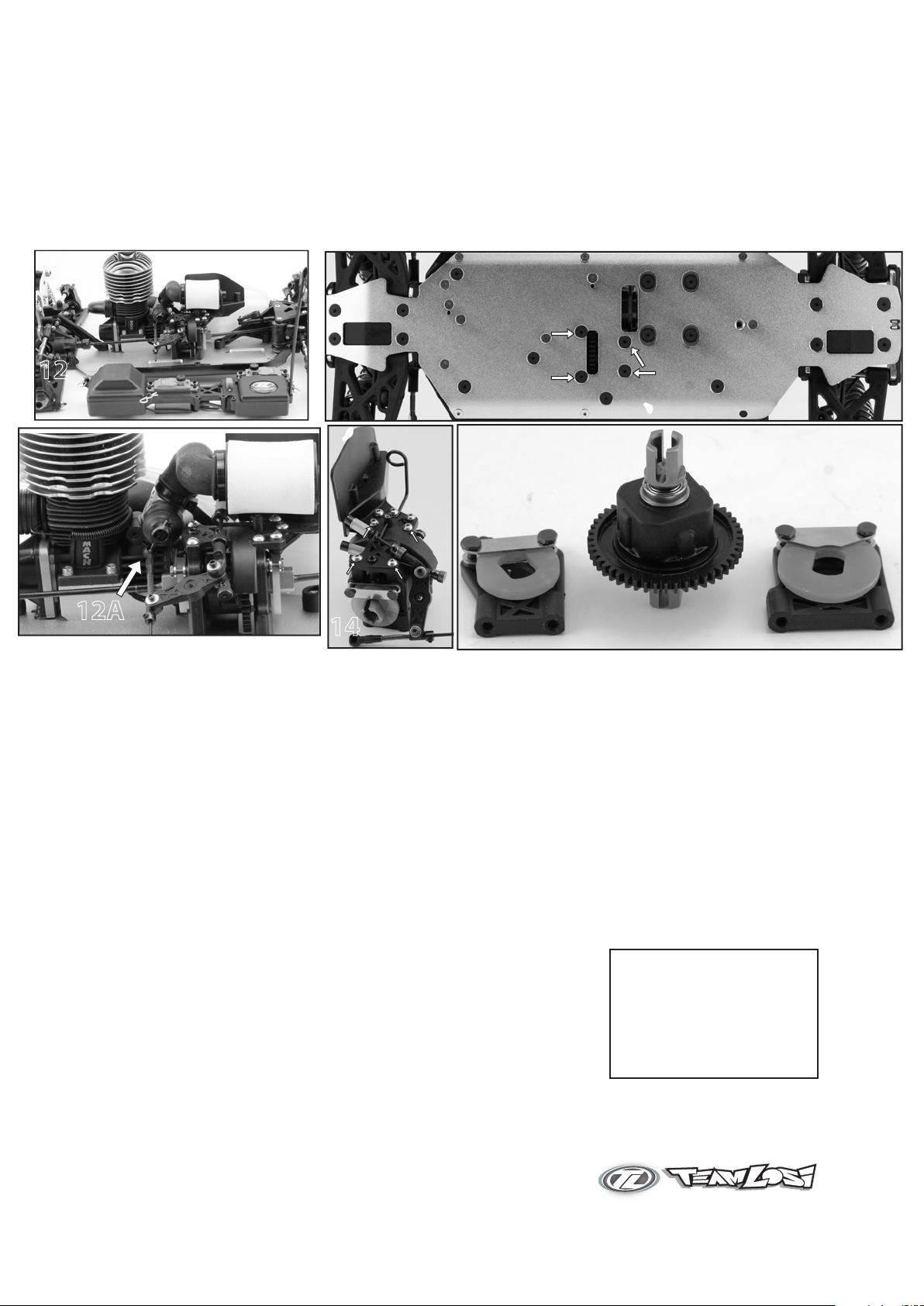
• Remove the radio tray from the chassis, (fig. 12).
• Pop the ball end off of the carburetor slide, fig. (12A)
• Remove four 8-32 x 1/2” flathead screws from the center differential housing, (fig. 13), and remove the
center diff from the chassis.
• Remove four 5-50 x 3/8” button head screws from the center top brace, (fig. 14).
• Slide the front and rear brake rotor assemblies off of the center diff, (fig. 15). NOTE: There are two
different size brake discs. The large disc is in the front brake assembly and the small disc is in the rear
brake assembly.
13
12
13
12A
14
Diff Service - Refer to exploded views on page 8.
• Remove the four 3mm flat head screws from the ring gear allowing it to be removed (use the 5/64 allen wrench).
• Inspect the ring and pinion gears for wear - replace if necessary.
• Remove the cross shafts and bevel gears from the carrier.
• Clean and inspect all parts - replace as needed.
• Check all ball bearings. Clean or replace as necessary.
• Lube all shafts and gears with LOSA3066 assembly grease and reassemble.
• Load cross shafts with gears into the carrier with extra grease. Apply the diff
seal gasket to the carrier and reinstall ring gear.
• Lube ring and pinion and with grease (LOSA #3066), and reassemble diff into diff housing.
• Grease the edges of the gear cases. This will ensure a dust free seal.
• Reinstall into chassis
For Viscous Differential
Instead of grease you can use Silicone fluid in the differential for a limited
slip feel as desired for racing. Simply fill the diff up to the top of the gears
before replacing the ring gear. (Be sure to reinstall the rubber gasket).
You may have to replace the o-rings on the outdrives at the same time
you change to this type of differential if the old ones are worn. Team Losi
recommends 5000cs. fluid for the front diff, 7000cs. fluid for the center diff,
and 2000cs. fluid for the read diff.
15
TEAM LOSI
SILICONE DIFF FLUID
A5278 - 2000 cs.
A5280 - 5000 cs.
A5281 - 7000 cs.
Page 7
Page 3

Front, Rear and Center Differential Exploded Views
1
2
3
4
1
2
3
4
Center DifferentialFront & Rear Differentials
Fill with 5000cs. oil (front) or
2000cs. oil (rear) just above the
planetary gear.
Fill with 7000cs. oil just
above the planetary
gear.
Tighten the diff screws
in this order
Tighten the diff screws
in this order
Page 8
Page 4

Clean the 2-56 x 1/4” button head screw and apply loctite to the threads.
Install the #55 shock piston using the 2-56 x 1/4” button screw into the shock shaft with a .050” allen wrench.
Place a drop of Shock Oil into the bottom of the Shock Body to lubricate the Shock Seals.
Thread the shock shaft into the shock end using pliers. Use caution when threading the shock shaft ends onto the shafts. Avoid gouging or scratching the shock
shaft while gripping the shock shaft with pliers by placing the edge of a towel over the shaft, then gripping the portion of the shaft covered by the towel. This method
will work very well to protect the shock shafts from damage.
Ensure the shaft is fully extended when filling the shock.
Fill the shock body with 35wt. shock oil until the oil is to the top of the body.
“Work” the shock shaft up and down a few times. This will release the air bubbles trapped beneath the piston. Place the filled shock, in the upright position, off to the side
for a few minutes until the air bubbles escape from the oil.
Once all the air bubbles are out of the oil, gently place the shock bladder onto the shock as shown. Some oil should “bleed” from the shock.
Screw the shock cap onto the body until some resistance is felt.
Slowly push the shock shaft up. This will bleed excess oil from the shock.
Tighten the cap all the way down using the shock tools included in your kit.
Move the shock shaft up and down. The shaft should be easy to push up into the body of the shock. If increased pressure is felt towards the top, there is to much oil in
the shock. Loosen the shock cap and “bleed” the shock as done previously.
Make sure each pair (front/rear) shocks have the same rebound and compression. This is checked by holding one shock in each hand horizontally and pushing them
together by the shock end. Watch carefully to ensure that both compress evenly. Now release both shocks and again watch carefully as they should rebound the same.
•
•
•
•
•
•
•
•
•
•
•
•
•
Rebuilding/Refilling the Shocks
Rebuilding/Refilling the Shocks
x2 x2
x 1
2-56 x 1/4”
Front
Rear
Page 9
Page 5

Quick Reference Guide
Quick Reference Guide
Initial Factory Settings
Initial Factory Settings
Engine
x 4
x2.5
Hi-Speed Needle - 4 turns out Low-Speed Needle 2.5 turns out
Shocks
Camber Links
4.07"
103.4mm
Rear Camber Link
Front Camber Link
3.72"
94.50mm
Steering Tie Rods
92.00mm
x5
3.62"
Team Losi 35wt
Shock Oil
(LOSA5225)
Page 10
Page 6

Losi 427 Customer Support
Horizon Hobby Inc
4105 Fieldstone Rd.
Champaign, IL 61821
1-877-504-0233
Trouble shooting Chart
Trouble shooting Chart
Problem Things To Check Remedy
Engine won't start.................................. Out of fuel
Spoiled or improper fuel
Glow plug not lighting
Glow igniter not charged
Engine overheating
Engine flooded
Air cleaner blocked
Exhaust blocked
Losi 427 Customer Support
Horizon Hobby Inc
4105 Fieldstone Rd.
Champaign, IL 61821
1-877-504-0233
Check/Replace Glow plug
Charge/change battery
Let cool - see "Testing the Teperature
Clean & reoil aircleaner
Engine won't turn over......................... Engine is flooded
Engine seized
Engine starts then stalls....................... Idle speed set too low
Glow plug is fouled/weak
Air bubbles in fuel line
Engine is overheated
Insufficient fuel tank pressure/blockage
Engine performing poorly.................. Hi-Speed fuel mixture is too rich
Engine overheating
Leaking glow plug
Carburetor dirty or blocked
Fuel bad or contaminated
Clutch slipping
Bound up drive-train
Engine worn out
Engine overheats................................... Hi-Speed fuel mixture is too lean
Low-Speed fuel mixture too lean
Spoiled or improper fuel
Cooling air is being blocked
Excessive load on the engine
Engine hesitates or stumbles............. Engine overheated
Hi-Speed mixture too lean
Low-Speed mixture to rich
Air bubbles in fuel line
Glow plug fouled
See "About Glow Plugs"
See "Engine Tuning"
See "About Glow Plugs"
Check for split/hole in fuel line
See "Testing the Temperature"
Clear pressure line
See "Engine Tuning"
Replace glow plug
Try fresh fuel
Clean/Adjust/Repair
Check for binds in drive-train
Rebuild
See "Understanding Rich and Lean
Clean head fins
Check for binds
See "Engine Tuning"
Check fuel line for holes
Change glow plug
Engine stalls instantly when throttle
is fully opened from idle...................... Glow plug fouled
Hi-Speed mixture too rich
Low-Speed mixture too lean
Engine stalls while driving around
turns............................................................ Fuel level is low
Idle speed set too low
Engine stalls while idling..................... Low-Speed mixture too rich
Low-Speed mixture too lean
Idle speed to low
Clutch shoes dragging
Clutch spring broken
Clutch bearings failed
Engine worn out
Page 11
Change glow plug
See "Engine Tuning"
Add Fuel
Increase Idle speed
See "Engine Tuning"
Increase idle speed
Check for broken clultch springs
Check/Clean/Replace
Rebuild
 Loading...