

Page 1
8IGHT/8IGHT-T
8IGHT/8IGHT-T
Starter Box
Starter Box
LOSA99061
LOSA99061
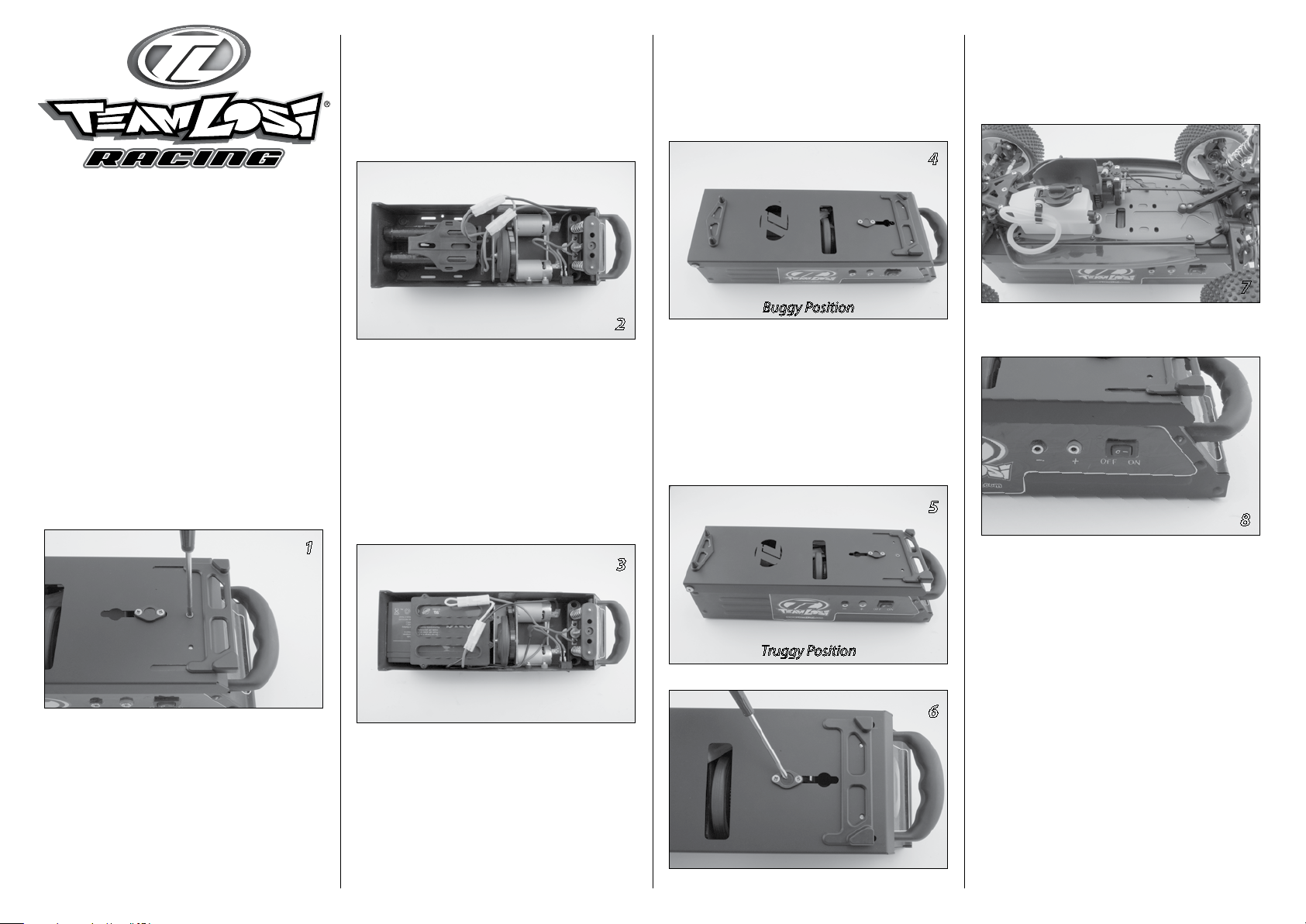
Installing the battery
You have several battery options to power your
8IGHT starter box. You can use 7.2V Ni-Cd or
Ni-MH battery packs or a single 12V gel cell.
Pre-assembled wiring harnesses and mounting
fixtures for both of these options are included.
Please note the proper mounting and wiring
layout in Images 2 and 3. Start by moving the
chassis fixtures to the truggy (Long) position
as seen in Images 4 through 6 and explained in
the “Adjusting the Chassis Fixtures” section and
remove the small Phillips head screw on the top
of the box as shown in Image 1.
Two 7.2V battery packs
Install the holder and packs as seen in
Image 2. Plug one pack into each of the plugs.
Note: The plugs are keyed so they can
only be installed one way.
2
Gel Cell
Install the holder and gel cell as seen in Image 3
or the wiring diagram on Page 2. Note the Red (+)
and Black (-) terminals on the battery. Install the
jumper plug and battery power plug as shown.
Unless you plan on using the power terminals
next to the switch, you must tape and/or cut the
ends of the loose battery leads. Do not leave these
exposed as they can easily short out the battery
and cause damage and a safety hazard.
Adjusting the chassis fixtures:
For the 8IGHT buggy—rotate the front fixture
with the “v” pointing toward the end of the box
as shown in Image 4. Depress the lock button as
shown in Image 6.
4
Buggy Position
Move the rear fixture to the innermost
(short) position.
For the 8IGHT-T truggy—rotate the front fixture
with the “v” pointing inward as shown in image 5.
Depress the lock button as in image 6 and move
the rear fixture to the outermost (long) position as
seen in Image 5.
5
Starting
Place the chassis into the fixtures as shown in
Image 7. Note how buggy chassis sits in fixtures
and location of starter wheel.
7
Turn the power switch “ON” (Image 8).
8
1
3
Truggy Position
Press down on the rear of the chassis at which
point the motors should power up and the starter
wheel will engage the flywheel on the engine.
Note: If the engine is new, tight, or
flooded, it may be necessary to loosen
the glow plug 2–3 turns to get it
turning over. Re-tighten after engine
6
starts turning over. Do not continue
to stall the motors or allow the rubber
wheel to grind on the flywheel or
chassis.
After the engine starts, release the chassis—it
should be able to sit in the fixtures and idle
without interference. Turn switch off.
1
Page 2
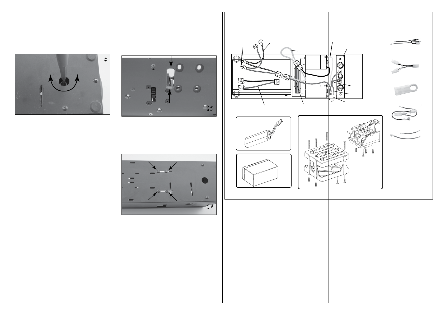
Adjusting the starter switch:
Sooner
Later
Connect to Power Ports
12V Gel Cell Harness
Jumper
*Pre-Wired at Factory
Starter Switch
12V Gel Cell Harness
Stick Pack Harness
Jumper
Wiring Harness
Red 87mm/131mm
12V 2Ah
Gel Cell
Battery Holder
7.2V
Battery Holder
7.2V Battery
(not included)
12V 2Ah Battery
(not included)
Stick Pack Harness
Wiring Harness
Power Switch
Red
131mm
Red
87mm
Wiring Diagram
Connect to
12V Battery
Terminals
You can adjust the starter switch and the point
at which the motors start running by turning
the Phillips head adjustment screw (accessible
through the hole in the bottom of box as seen
in Image 9).
Tech/Service Tips
• On some models it may be necessary to relieve
the ends of the flywheel opening on the
bottom of your chassis (Image 10) to prevent
the chassis from interfering with the starter
wheel and allow the wheel easy access to
engage the flywheel on the engine.
9
10
Turning the adjustment screw counterclockwise
will allow the motors to start sooner and have
better starting power. Turning the adjustment
screw clockwise will start the motors later and give
you more travel before the motors start to power
up. You may want to adjust this to compensate for
starter wheel wear.
Ideally, the motors should start when the top plate
is depressed about 1/8-inch. If you find that the
motors are easily stalled while trying to start your
8IGHT, adjust the starter switch as noted above so
that the motors start sooner.
Troubleshooting Guide
Motors run slow
Battery(s) needs to be charged
Starter wheel won’t turn over engine
Loosen glow plug
Adjust switch to motors start sooner
Put a few drops of fuel in carburetor
Check for wheel interference with chassis
(See Image 10)
Check for starter wheel wear
• It’s a good idea to use compressed air to clean
• To replace the starter wheel, remove the four
Disconnect the wires from the motor and
the dust and dirt out of the starter box.
screws in the center of the box bottom as
indicated in Image 11.
11
mark the location of the mounting screws
before removing. Remove the screws on
either side of the wheel shaft. After replacing
the wheel, be sure to re-install the assembly
in its original position.
2
Page 3

Exploded View
LOSA99411
LOSA99411
LOSA99412
LOSA99412
LOSA99410
LOSA99401
LOSA99407
LOSA99408
LOSA99412
LOSA99405
LOSA99402
LOSA99412
LOSA99404
LOSA99403
LOSA99410
Replacement Parts
Part # Description Price
LOSA99401 Starter Box Wheel (8) 3.99
LOSA99402 Starter Box Pulley (8) 4.99
LOSA99403 Motor Pulley Set (8) 2.99
LOSA99404 Starter Drive Belt (8) 7.99
LOSA99405 Starter Switch Set—Adjustable (8) 6.99
LOSA99407 Starter 550 Motor w/Screws (8) 14.99
LOSA99408 Starter Rubber Feet (4ea) (8) 2.99
LOSA99410 Starter Front Chassis Fixture (8) 7.99
LOSA99411 Starter Rear Chassis Fixture (8) 9.99
LOSA99412 Starter Misc Hardware Set (8) 3.50
3
Page 4

Warranty Period
Exclusive Warranty- Horizon Hobby, Inc.,
(Horizon) warranties that the Products
purchased (the “Product”) will be free from
defects in materials and workmanship at the
date of purchase by the Purchaser.
Limited Warranty
(a) This warranty is limited to the original
Purchaser (“Purchaser”) and is not transferable.
REPAIR OR REPLACEMENT AS PROVIDED UNDER
THIS WARRANTY IS THE EXCLUSIVE REMEDY OF
THE PURCHASER. This warranty covers only those
Products purchased from an authorized Horizon
dealer. Third party transactions are not covered
by this warranty. Proof of purchase is required
for warranty claims. Further, Horizon reserves the
right to change or modify this warranty without
notice and disclaims all other warranties, express
or implied.
(b) Limitations- HORIZON MAKES NO
WARRANTY OR REPRESENTATION, EXPRESS
OR IMPLIED, ABOUT NON-INFRINGEMENT,
MERCHANTABILITY OR FITNESS FOR A PARTICULAR
PURPOSE OF THE PRODUCT. THE PURCHASER
ACKNOWLEDGES THAT THEY ALONE HAVE
DETERMINED THAT THE PRODUCT WILL SUITABLY
MEET THE REQUIREMENTS OF THE PURCHASER’S
INTENDED USE.
(c) Purchaser Remedy- Horizon’s sole obligation
hereunder shall be that Horizon will, at its option,
(i) repair or (ii) replace, any Product determined by
Horizon to be defective. In the event of a defect,
these are the Purchaser’s exclusive remedies.
Horizon reserves the right to inspect any and all
equipment involved in a warranty claim. Repair or
replacement decisions are at the sole discretion
of Horizon. This warranty does not cover cosmetic
damage or damage due to acts of God, accident,
misuse, abuse, negligence, commercial use, or
modification of or to any part of the Product. This
warranty does not cover damage due to improper
installation, operation, maintenance, or attempted
repair by anyone other than Horizon. Return of any
goods by Purchaser must be approved in writing
by Horizon before shipment.
4
Damage Limits
HORIZON SHALL NOT BE LIABLE FOR SPECIAL,
INDIRECT OR CONSEQUENTIAL DAMAGES, LOSS
OF PROFITS OR PRODUCTION OR COMMERCIAL
LOSS IN ANY WAY CONNECTED WITH THE
PRODUCT, WHETHER SUCH CLAIM IS BASED IN
CONTRACT, WARRANTY, NEGLIGENCE, OR STRICT
LIABILITY. Further, in no event shall the liability
of Horizon exceed the individual price of the
Product on which liability is asserted. As Horizon
has no control over use, setup, final assembly,
modification or misuse, no liability shall be
assumed nor accepted for any resulting damage
or injury. By the act of use, setup or assembly, the
user accepts all resulting liability.
If you as the Purchaser or user are not prepared to
accept the liability associated with the use of this
Product, you are advised to return this Product
immediately in new and unused condition to the
place of purchase.
Law: These Terms are governed by Illinois law
(without regard to conflict of law principals).
Safety Precautions
This is a sophisticated hobby Product and not a
toy. It must be operated with caution and common
sense and requires some basic mechanical
ability. Failure to operate this Product in a safe
and responsible manner could result in injury
or damage to the Product or other property.
This Product is not intended for use by children
without direct adult supervision. The Product
manual contains instructions for safety, operation
and maintenance. It is essential to read and follow
all the instructions and warnings in the manual,
prior to assembly, setup or use, in order to operate
correctly and avoid damage or injury.
Questions, Assistance, and Repairs
Your local hobby store and/or place of
purchase cannot provide warranty support or
repair. Once assembly, setup or use of the
Product has been started, you must contact
Horizon directly. This will enable Horizon to
better answer your questions and service
you in the event that you may need any assistance.
For questions or assistance, please direct your
email to productsupport@horizonhobby.com, or
call 877.504.0233 toll free to speak to a service
technician.
Inspection or Repairs
If this Product needs to be inspected or repaired,
please call for a Return Merchandise Authorization
(RMA). Pack the Product securely using a shipping
carton. Please note that original boxes may be
included, but are not designed to withstand the
rigors of shipping without additional protection.
Ship via a carrier that provides tracking and
insurance for lost or damaged parcels, as Horizon
is not responsible for merchandise until it
arrives and is accepted at our facility. A Service
Repair Request is available at www.horizonhobby.
com on the “Support” tab. If you do not have
internet access, please include a letter with your
complete name, street address, email address
and phone number where you can be reached
during business days, your RMA number, a list of
the included items, method of payment for any
non-warranty expenses and a brief summary of
the problem. Your original sales receipt must also
be included for warranty consideration. Be sure
your name, address, and RMA number are clearly
written on the outside of the shipping carton.
Warranty Inspection and Repairs
To receive warranty service, you must
include your original sales receipt verifying
the proof-of-purchase date. Provided warranty
conditions have been met, your Product will be
repaired or replaced free of charge. Repair or
replacement decisions are at the sole discretion of
Horizon Hobby.
Non-Warranty Repairs
Should your repair not be covered by warranty
the repair will be completed and payment will
be required without notification or estimate of
the expense unless the expense exceeds 50%
of the retail purchase cost. By submitting the
item for repair you are agreeing to payment of
the repair without notification. Repair estimates
are available upon request. You must include this
request with your repair. Non-warranty repair
estimates will be billed a minimum of ½ hour
of labor. In addition you will be billed for return
freight. Please advise us of your preferred method
of payment. Horizon accepts money orders
and cashiers checks, as well as Visa, MasterCard,
American Express, and Discover cards. If you
choose to pay by credit card, please include your
credit card number and expiration date. Any repair
left unpaid or unclaimed after 90 days will be
considered abandoned and will be disposed of
accordingly. Please note: non-warranty repair
is only available on electronics and model
engines.
Electronics requiring inspection or repair should
be shipped to the following address:
Horizon Service Center
4105 Fieldstone Road
Champaign, Illinois 61822
All other Products requiring warranty
inspection or repair should be shipped to the
following address:
Contact Losi:
4710 East Guasti Road
Ontario, CA 91761
(909)390-9595
feedback@teamlosi.com
Please call 877-504-0233 with any
questions or concerns regarding this
product or warranty.
©2007 Team Losi Racing is an exclusive brand of
Horizon Hobby, Inc.
4105 Fieldstone Rd.
Champaign, IL 61822
Customer Support
1-877-504-0233
www.horizonhobby.com
www.losi.com
part# 800-032 4
10624
 Loading...