

Losi LOSA0887 User Manual

Carefully read through all instructions to familiarize yourself with the parts, construction
techniques, and tuning tips outlined in this manual. Being able to grasp the overall design of
yo
ur new XXX-NT Sport RTR II truck before beginning any disassembly process will ensure a successful
rebuild.
Take your time and pay close attention to detail. Keep this manual for future reference.
Service and Technical questions
A Division of Horizon Hobby Inc.
4710 E. Guasti Road, Ontario, CA 91761
www.TeamLosi.com - feedback@TeamLosi.com
Radio & Engine:(877) 504-0233 (Horizon Hobby)
Chassis only:(909) 390-9595 (Team Losi)
800-0253

WELCOME XXX-NT SPORT OWNER!
Thank you for choosing the Team Losi XXX-NT Sport as your vehicle to enjoy the exciting world of nitro powered all-terrain racing. The
XXX-NT Sport is the result of hundreds of hours of computer-aided design and on-track testing by our world champion development
team. The XXX-NT Sport represents the latest in technology and meets the unique demands of nitro powered off-road racing.
Since fuel powered models tend to require greater mechanical tuning ability, it is important that you read through this manual
completely before beginning assembly. A little extra time now will save building time and help get your new truck running sooner. You
will find that our unique bag-by-bag assembly is both quick and easy to follow. You will also notice that we have included a separate
tip section along with helpful hints throughout this manual to help you tune your XXX-NT Sport and maximize your enjoyment of this
model.
Once again, thank you for making a wise choice… the XXX-NT Sport.
Team Losi
1. INTRODUCTION
XXX-NT SPORT COMPLETED DIMENSIONS
Length: 16-1/2" Front Width: 12-3/4" Rear Width: 12-3/4" Height: 5-1/4"
Wheel base: 11-1/4" All dimensions at ride height. Weight will vary depending on accessories.
NOTES & SYMBOLS USED
Figure 1
This is a common figure number found at the beginning of each
new illustration throughout the manual.
Step 1. - Each step throughout the entire manual has a check box
to the left of it. As you complete each step, mark the box with a check.
If you need to take a break and return to building at a later time you will
be able to locate the exact step where you left off.
*NOTE: This is a common note. It is used to call attention to
specific details of a certain step in the assembly.
IMPORTANT NOTE: Even if you are familiar with T eam
Losi kits, be sure and pay attention to these notes. They point
out very important details during the assembly process. Do not
ignore these notes!
Tip: This designates a performance tip. These tips are not neces-
sary, but can improve the performance of your
XXX-NT Sport truck.
In illustrations where it is important to note which
direction parts are pointing, a helmet like this one will be included in the illustration. The helmet will always face the front of
the car. Any reference to the right or left side will relate to the
direction of the helmet.
KIT/MANUAL ORGANIZA TION
The XXX-NT Sport is composed of different bags marked A through
F. Each bag contains all of the parts necessary to complete a
particular section of the truck. Some of these bags have subassembly bags within them. It is essential that you open only one
bag at a time and follow the correct sequence, otherwise you
may face difficulties in finding the right part. It is helpful to read
through the instructions for an entire bag prior to starting assembly. Key numbers (in parentheses) have been assigned to each
part and remain the same throughout the manual. In some illustrations, parts which have already been installed are not shown
so that the current steps can be illustrated more clearly.
For your convenience, an actual size hardware identification guide
is included with each step. To check a part, hold it against the silhouette until the correct part is identified. In some cases extra hardware
has been supplied for parts that may be easy to lose.
The molded parts in the XXX-NT Sport are manufactured to demanding tolerances. When screws are tightened to the point of being
snug, the parts are held firmly in place. For this reason it is very important that screws not be overtightened in any of the plastic parts.
T o insure that parts are not lost during construction, it is recommended that you work over a towel or mat to prevent parts from rolling
away.
IMPORT ANT SAFETY NOTES
1. Select an area for assembly that is away from the reach
of small children. The parts in the kit are small and can be swal-
lowed by children, causing choking and possible internal injury.
2. The shock fluid and greases supplied should be kept out
of children’s reach. They were not intended for human consump-
tion!
3. Exercise care when using any hand tools, sharp instru-
ments, or power tools during construction.
4. Carefully read all manufacturer’s warnings and cautions
for any glues, fuel, or paints that may be used for assembly and
operating purposes.
5. Gas powered vehicles should not be operated indoors.
6. Be careful when handling your truck after it has been run
for any period of time. The engine and many parts can get extremely hot during operation.
TOOLS REQUIRED
Team Losi has supplied all Allen wrenches and a special wrench
that is needed for assembly and adjustments. The following
common tools will also be required: Small flatblade screwdriver,
Phillips screwdriver, needle nose pliers, regular pliers, scissors,
or other body cutting/trimming tools. 3/16", 1/4", 5/16", and 3/8"
nut drivers are optional.
i

RADIO/ELECTRICAL
Refer to the included JR Propo XR2i owners manual for specific technical information.
HARD
WARE IDENTIFICATION
in quest ion, use the hardware identific atio n guide in each step. For scre ws, th e prefix number desig nates the
When
size and number of threads per inch (i.e. , 4-40 is #4 screw with 40 thr eads per inch of length). The frac tion
screw
following
and
are described by inside diameter or the screw size that will pass through the inside diameter. E-clips are sized by the shaft
diameter
The
flammabl e
packaging
operated
towards
There are a number of different brands of model fuels available. We have found that fuels specially blended for R/C car
like Blue Thunder, Trinity, and Orion perform better than common model airplane or helicopter fuels. Model airplane
use
fuels
You will need some sort of a fuel bottle in order to fill the tank in your XXX-NT Sport with fuel. Your local hobby shop
should
designates the length of the threads for cap head screws, and the overall length for flathead screws. Bearings
bushings are referenced by the inside diameter x outside diameter. Shafts and pins are diameter x length. Washers
th at they are att ached to.
FUEL
fuel used to power the XXX-NT Sport truck is a special blend of methanol, oils, and nitromethane. This fuel is highly
and should be treated with extreme caution. Be sure to read any warnings and cautions that appear on the
of the fuel. Because exhaust fumes are produced from running fuel powered models, this model should not be
indoors. Be careful when handling your truck while the motor is running. Avoid pointing the exhaust outlet
your face. The exhaust fumes can cause irritation and burning of the eyes.
usually do not have the proper type or amount of oil needed for the extreme demands of R/C car racing.
BOTTLE
FUEL
have fuel bottles available.
Service and Technical questions
Radio & Engine:(877) 504-0233 (Horizon Hobby)
Chassis only:(909) 390-9595 (Team Losi)
TABLE OF CONTENTS
1. INTRODUCTION ..................................................................... i
Completed
Notes
Kit
Manual Organization ..................................................... i
Important
Tools Required ..................................................................... i
Radio/Electrica
Hardware
Kit Dimensions ................................................ i
& Symbols ................................................................ i
Safety Notes ....................................................... i
l .................................................................. ii
Identification ...................................................... ii
2. BAG A .................................................................................1-6
3. BAG B ............................................................................... 7-11
4. BAG C ............................................................................ 12-21
5. BAG D ............................................................................ 22-26
6. BAG E............................................................................ 27-30
7. BAG F .................................................................................. 31
8. Engine Installation ........................................................ 32-39
9.
Radio Installation .......................................................... 40-51
Fu
el ...................................................................................... ii
Fuel
Bottle ........................................................................... ii
Starters ................................................................................ ii
Glow Igniter ......................................................................... ii
Team Losi is continually changing and improving designs ; therefore, the actual part may appea r slightly different than the illustrated part. Illustrations of
parts and asse mb li es may be slig ht ly distorted t o enhance pertinent deta il s.
10.
Final Assembly ................................................................... 52
11. Final Checklist .................................................................... 53
12.
Tips from the Team ....................................................... 53-55
13.
Spare parts .................................................................... 56-59
ii
3
3
7
1
11
8
1
Figure 1
BAG A
6
6
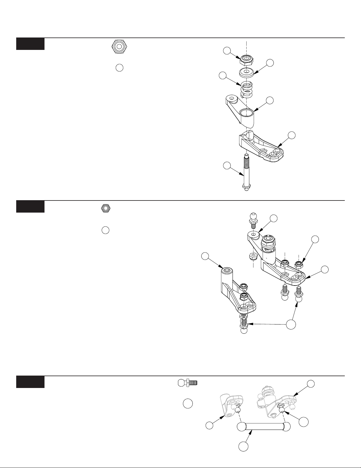
Step 1. Place the servo saver bottom (1) over the servo saver post (2)
and slide the servo saver bottom all the way against the hex at the
opposite end. Be sure that the hex on the servo saver post (2) is
inserted into the hex in the servo saver bottom (1).
Step 2. Slide the servo saver top (3) down over the servo saver post
(2) so that the 'V' area of the servo saver top (3) rests in the 'V' area of
the servo saver bottom (1). The arm on the servo saver top (3) and the
arm on the servo saver bottom (1) should point in opposite directions
as shown in Figure 1.
Step 3. Slide the servo saver spring (4) over the servo saver post (2)
and push it into the recessed area of the servo saver top (3). Install
the servo saver spring cap (5) and thread the 6-40 locknut (6) onto the
end of the servo saver post (2).
Step 4. Tighten the 6-40 locknut (6) all the way down and then loosen
it two full turns (e.g. 360o x 2). This is a good starting point for the
adjustment. Once assembly is complete, if you wish, the servo saver
can be adjusted tighter or looser.
Figure 2
7
Step 5. Insert a 4-40 mini locknut (7) into the outer hex area in the
servo saver bottom (1) and steering idler arm (8) as shown in Figure 2.
Thread a 3/16" ball stud (11) through the outside hole in each arm,
into the nuts (7), and tighten. Insert a 4-40 mini locknut (7) into the hex
area in the servo saver top (3). Thread a 3/16" ball stud (11) through
the hole in the arm, into the nut (7), and tighten.
Step 6. Insert a 4-40 mini locknut (7) into the hex areas in the rear of the
servo saver bottom (1) and the steering idler arm (8) as shown in
Figure 2. Thread a 3/16" ball stud (11) through the arms, into each nut
(7), and tighten.
Tip: Once assembly of your new XXX-NT is complete, you may
notice that the tires toe in slightly as the suspension compresses. W e
have found this setting to yield the best performance. Should you
prefer to change this so that the tires do not toe in, you can add one
ball stud washer under the ball studs on the outside of the servo
saver assembly and steering idler arm. T o accomplish this, you will
want to replace the 3/16" ball studs with 1/4" ball studs.
5
4
3
2
Figure 1
Figure 2
Figure 3
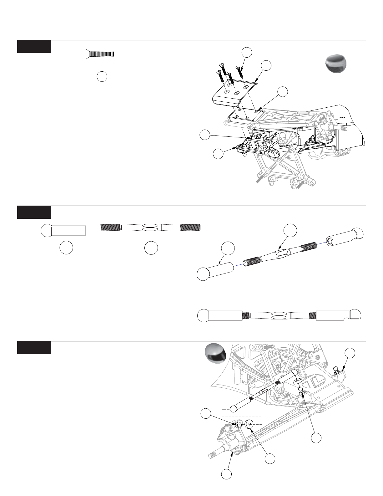
Step 7. Snap one end of the steering drag link (12) to the rear ball
stud (11) on the servo saver bottom (3). Snap the other end to the rear
ball stud (11) on the steering idler arm (8).
*NOTE: Be sure to snap the rod onto the correct ball studs as
shown!
11
8
12
1
11
Figure 3
4
4
BAG A (Continued)
3
Figure 4
1
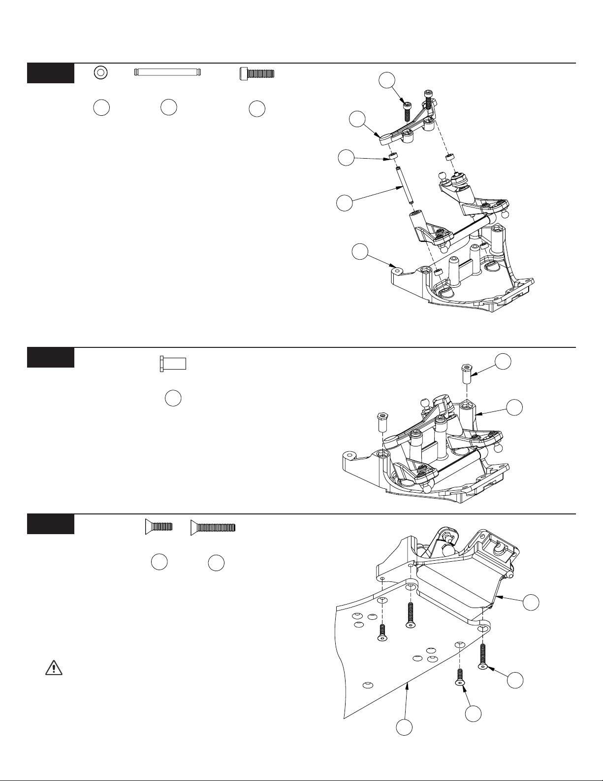
Step 8. Insert a 3/32" x 3/16" plastic bushing (13) into the two large,
angled holes in the bottom of the front kickplate (14). Insert the other
two bushings (13) into the two outer holes in the steering brace (15).
Step 9. Insert a 3/32" x .930" hinge pin (16) through the hole in the
steering idler arm (8) and center the pin (16) in the idler arm (8). Place
the servo saver assembly and the steering idler arm (8) into the bushings (13) in the kickplate (14) so that the
installed drag link is to the front as shown in Figure 4.
Step 10. Place the steering brace (15) on top of the servo saver assembly and steering idler arm (8) ensuring that the bushings (13) slide
over the pins.
Step 11. Secure the steering brace (15) to the kickplate (14) using two
4-40 x 3/8" cap-head screws (17).
Tip: There is a short thread-cutting screw included in the wrench
bag. This screw can be used to tap threads in the holes in the
kickplate. Pre-tapping these holes makes it easier to install the
screws during assembly.
16
17
Figure 5
17
15
13
16
14
Figure 4
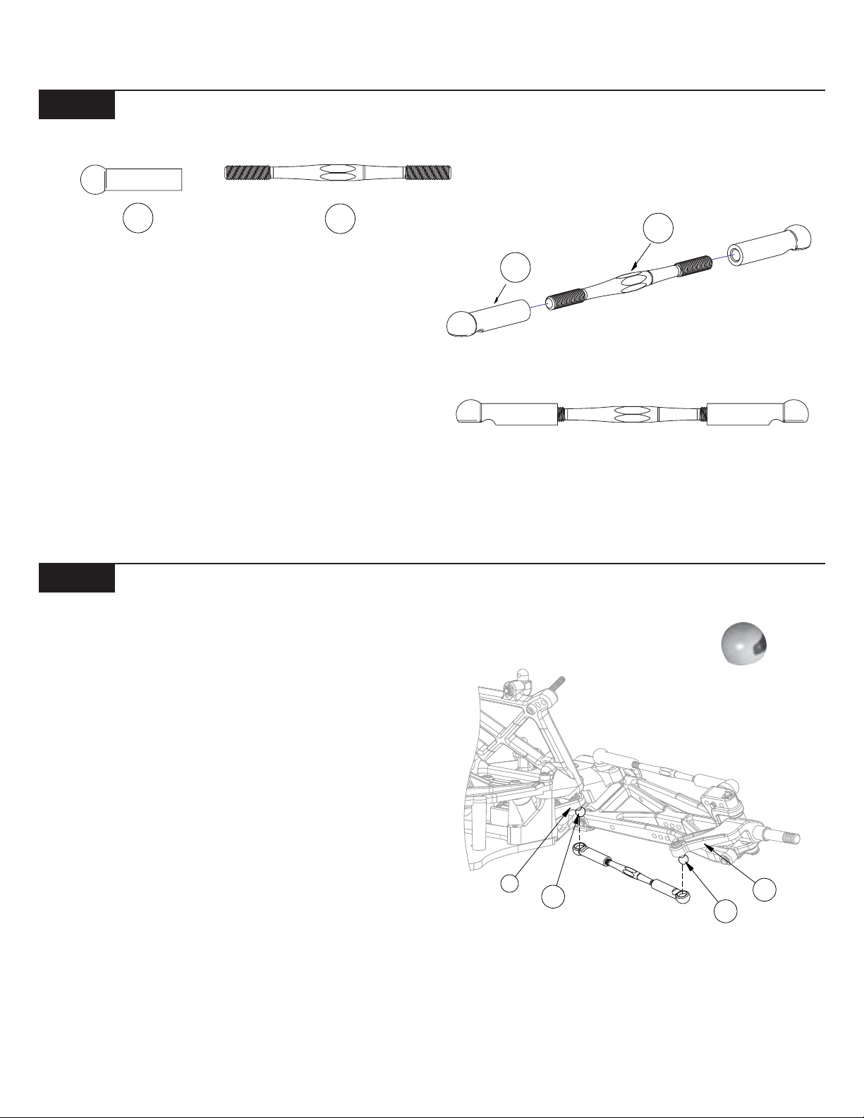
18
18
Step 12. Install a threaded insert (18) into the top of each of the two
forward holes in the kickplate (14). The inserts should be installed
with the hex-side up as shown in Figure 5. Press the threaded inserts
(18) all the way into the holes in the kickplate (14), lining up the hex on
the inserts (18) with the hex in the holes.
Figure 6
20
Step 13. Attach the front kickplate (14) to the bottom of the main
chassis (19). Align the four holes in the kickplate (14) with the four
holes in the main chassis (19). Secure the kickplate (14) to the chassis
(19) by threading two 4-40 x 5/8" flat-head screws (21) through the
forward holes and into the threaded inserts (18). Thread two more 440 x 3/8"(20) flat-head screws through the two rear holes of the chassis (19) and into the kickplate (14).
IMPORT ANT NOTE: Ensure that the hex of the threaded
insert remains seated in the hex area on top of the
kickplate.
Tip: There is a short thread-cutting screw included in the wrench
bag. This screw can be used to tap threads in the holes in the
kickplate. Pre-tapping these holes makes it easier to install the
screws during assembly.
21
1
Figure 5
1
21
20
19
Figure 6
2
7
BAG A (Continued)
Figure 7
7
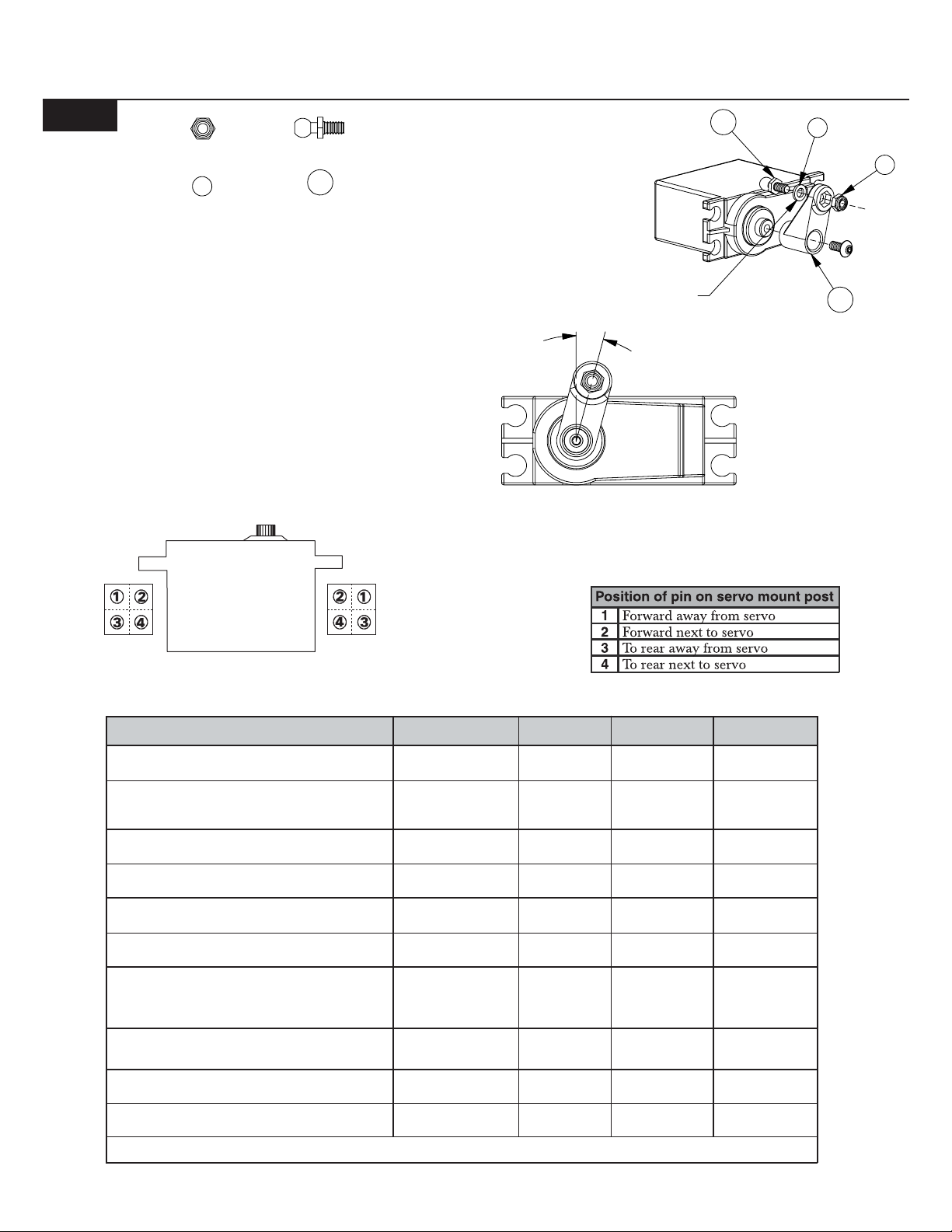
Step 14. Using T able 7C, determine which servo arm (22) is required
for your servo. If your particular servo is not listed, try using the arm
recommended for another servo made by the same manufacturer.
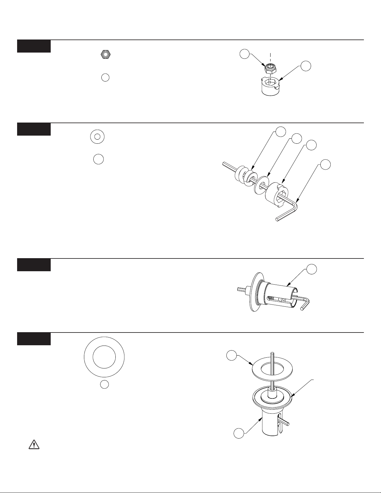
Step 15. Insert a 4-40 mini locknut (7) into the hex area of the servo arm
(22). Thread a 3/16" ball stud (11) through the hole in the arm (22), into
the locknut (7), and tighten.
Step 16. Plug the servo into the radio system's receiver (not included).
Make sure that there is power to the receiver, and turn the transmitter
on followed by the receiver. Be sure that the trim settings for the
steering on your transmitter are set to the center. With the radio system still turned on, attach the servo arm (22) to the output shaft so
that the arm is one spline off center in the direction shown in Figure
7A. Secure the arm (22) with the servo arm screw supplied with the
servo.
11
Ball stud washer
required for
some servos
15.00˚
11
9
22
Figure 7
Figure 7A
Figure 7B
*Note: Posts are not to scale.
SERVO TYPE
Airtronics
All
Futaba
S131, S131SH, S148, S3001, S3003, S5101,
S9101, S9201, S9301, S9304, S9401, S9403
Futaba
S3401, S9402, S9404, S9450
Futaba
S9303
HiTech
HS-605, HS-615, HS-925, HS-945
HiTech
All others
JR
NES-507, NES-513, NES-517, NES901, NES-4000,
NES-4131, NES-4721, NES-4735, NES-9021,
DS-8231
KO
PS-702, PS-703, PS-1001, PS-1003
KO
PS-901BH, PS-902
Multiplex
All
**Use 1 ball stud washer on the ball stud when attaching it to the servo arm
MOUNTING POST
PIN LOCATION
3 23 10A
2
3
4**
3**
1
1
2
1
3
REQUIRED
SERVO ARM
25
25
25
24
24
23
23
23
23
STEERING
LINK LENGTH
10A
10A
10A
10B
10B
10A
10A
10A
10A
THROTTLE
SERVO POSTS
NARROW
WIDE
NARROW
WIDE
NARROW
NARROW
NARROW
WIDE
NARROW
NARROW
Figure 7C
3
24
23
17
25
24
19
Figure 8
3
BAG A (Continued)
17
Step 17. Use the tables in Figure 7B and 7C (on the previous page) to
determine how the servo mounting posts (24) should be attached to
the servo (not included).
Tip: Trim any flashing from the pins on the mounting posts so that
they will seat all the way into the holes in the chassis brace and
chassis.
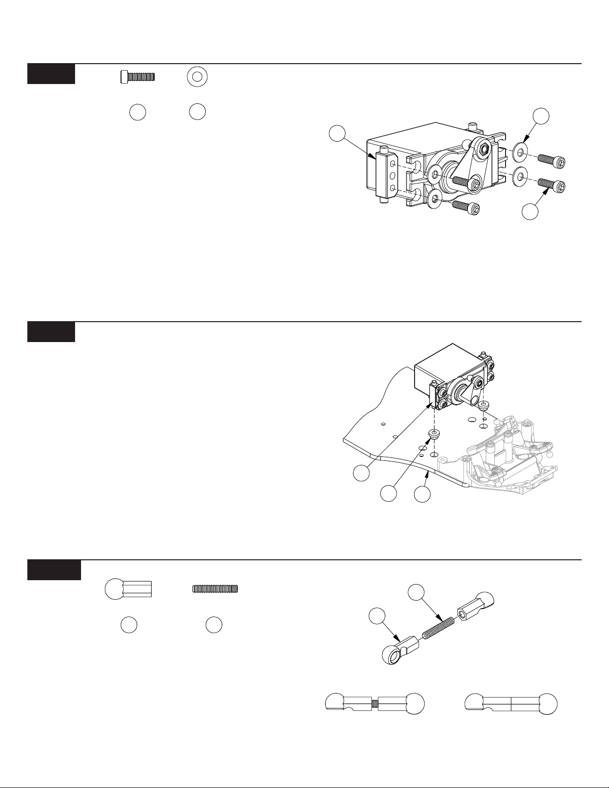
Step 18. Place a #4 washer (23) over each of the four 4-40 x 3/8" caphead screws (17) and attach the servo posts (24) to the servo by
threading a screw (17) through the upper and lower holes in each
post (24). Do not tighten the screws (17) yet! Just snug them up so
that the posts are held in place, but can still be moved from side to
side with a little resistance. The screws (17) will be tightened after the
servo is installed so that the posts (24) have the correct spacing.
2
Figure 9
Step 19. Install the steering post bushings (25) into the forward holes
in the chassis (19) as shown in Figure 9. Insert the pin on the left
servo post (24) into the hole in the servo post bushing (25). Move the
servo and posts (24) slightly until both the left and right posts (24)
are inserted in the holes in the servo post bushings (25). Make sure
bothe servo mounting posts (24) are perpendicular to the chassis,
and tighten down all four servo mounting screws (17).
Tip: There are two sets of servo mounting holes in the chassis.
Mounting the servo in the forward set of holes will give the best
overall performance. However, the servo may be mounted in the
rear set of holes to increase rear traction and improve handleing
on very slippery tracks. If the servo is mounted in the rear holes, you
must reverse the ball stud in the servo arm so that the ball points
forward.
Figure 8
Figure 9
Figure 10
26
Step 20. Thread a short plastic rod end (26) onto each end of the 4-40
x 5/8" threaded rod (27).
Step 21. Refer to table in Figure 7C (on the previous page) to determine the appropriate rod length for the servo that is installed. Tighten
both sides equally until the rod is the same length as the one shown
in Figure 10A or 10B.
27
27
26
Figure 10
Figure 10A
4
Figure 10B
BAG A (Continued)
3
Figure 1 1
Step 22. Attach one end of the rod to the ball stud (11) in the servo
arm (22) and the other to the ball stud (11) in the servo saver top (3) as
shown in Figure 11.
Figure 12
28
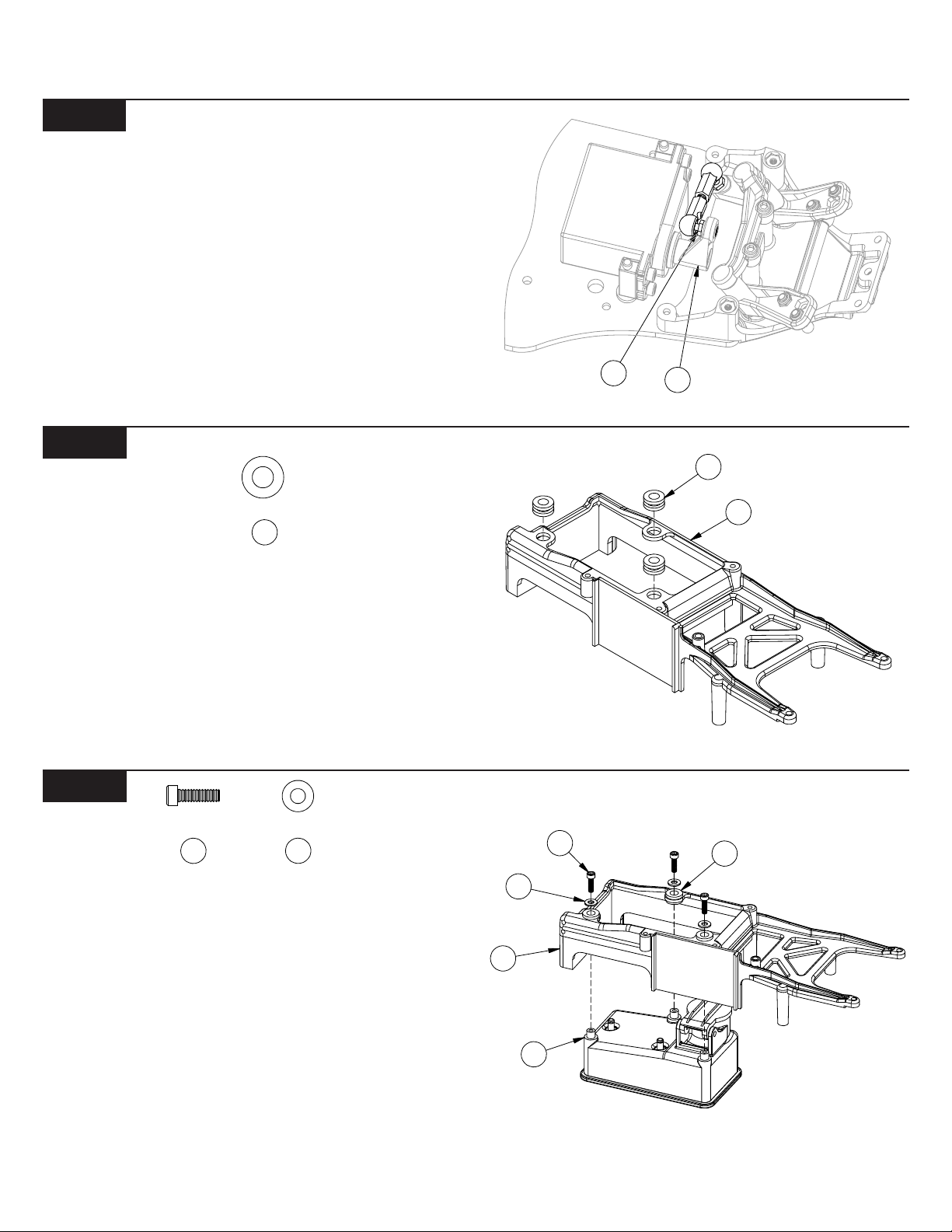
Step 23. Press a rubber tank-mounting grommet (28) into each of the
three large holes in the top of the chassis brace (29) as shown. The
grommets (28) should be centered, top-to-bottom, in the holes of the
chassis brace.
Figure 13
11
Figure 12
22
Figure 11
28
29
17
Step 24. Line up the three posts on the fuel tank (30) with the three
holes with grommets in the chassis brace (29). Install the fuel tank
(30) on the chassis brace (29) from the bottom by pressing the three
posts on the tank (30) through the three rubber grommets (28).
Step 25. Place a #4 washer (23) over each of the three 4-40 x 3/8" caphead screws (17). Thread a screw (14) through each of the grommets
(28) and into the posts in the fuel tank (28). Hold the tank (30) all the
way up against the chassis brace (29). Tighten each of the three
screws (14) until the washer (23) just touches the grommet (28).
*NOTE: The screws should not be tightened so that grommet
smashes. By tightening the screws until the washers just touch the
grommets, the tank will be "shock mounted". This helps the fuel
from foaming while running the truck.
2
17
23
29
30
Figure 13
5
28
BAG A (Continued)
Figure 14
20
Step 26. Place the chassis brace (29) on top of the chassis (19). Pay particular attention to the servo posts (24). The pins in the top of the servo
posts (24) should fit into the two holes in the chassis brace (29). Once the chassis brace (29) is lined up and in place, secure it to the chassis (19)
with six 4-40 x 3/8" flat-head screws (20) as shown.
*NOTE: Make sure that the pins on the top and bottom of the servo posts stay located in the holes in the servo post bushings and chassis
brace, and that the servo is as close to centered between the two servo posts as possible.
Tip: There is a short thread-cutting screw included in the wrench bag. This screw can be used to tap threads in the holes in the top chassis
brace. Pre-tapping these holes makes it easier to install the screws during assembly.
29
24
20
Figure 14
6
2
34
35
36
33
7
37
Figure 15
9
5
BAG B
20
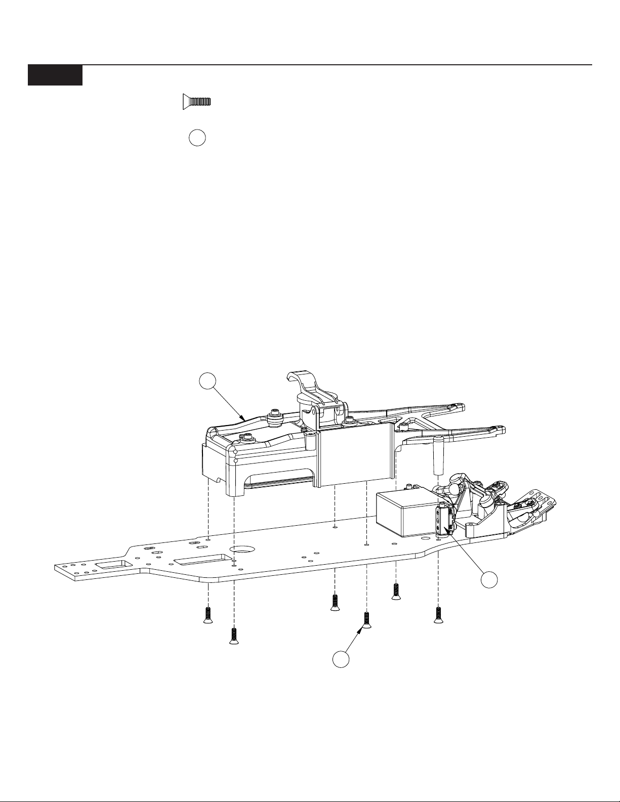
Step 1. Position the front bulkhead (32) between the front kickplate
(14) and the chassis brace (29), as shown in Figure 15. Place a ball
stud washer (9) over the two 4-40 x 1/2" cap-head screws (31). Secure
the front bulkhead (32) to the front kickplate (14) by threading the
screws (31) through the holes in the top of the chassis brace (29)
through the front bulkhead (32) and into the front kickplate (14).
Step 2. Secure the front kickplate (14) to the front bulkhead (32) by
threading a 4-40 x 3/8" flat-head screw (20) through the center hole in
the front of the kickplate (14) and into the bulkhead (32).
31
29
14
Figure 15
31
9
3
20
Figure 16
33
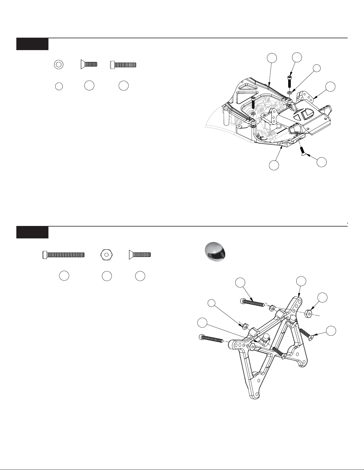
Step 3. Insert two 4-40 x 7/8" cap-head screws (33) — one on each
side — through the second hole out in the top of the front shock
tower (34). Secure the screws (33) to the shock tower (34) by threading a 4-40 nut (35) over each screw (33) and tightening.
Tip: Use the included Team Losi wheel wrench/nut-driver.
Step 4. Press a 4-40 mini locknut (7) into the hex area in the top, rear of
each side of the front shock tower (34). Insert a 4-40 x 1/2" flat-head
screw (36) into each of the two front body mounts (37) from the side
with the recess for the head of the screw (36)
Step 5. Attach a front body mount (37) to the front of each side of the
front shock tower (34) so that the posts point up as shown in Figure
16. Secure the body mounts (37) by threading the screws (36) through
the tower (34) and into the locknuts (7).
3
36
Figure 16
7
9
7
2
4
6
Figure 17
9
6
7
BAG B (Continued)
17
Step 6. Attach the front shock tower (34) to the front bulkhead (32)
with four 4-40 x 3/8" cap-head screws (17). The screws (17) thread
into the top-most and bottom-most holes in the bulkhead (32). The
center holes are not used.
IMPORTANT NOTE: The screws in the top of the shock
tower must be pointing forward as shown in Figure 17.
Step 7. Place a ball stud washer (9) over each of the two 3/8" ball
studs (38). Thread a 3/8" ball stud (38) into the center hole on each
side of the front bulkhead (32).
38
Figure 18
34
38
1
32
Figure 17
44
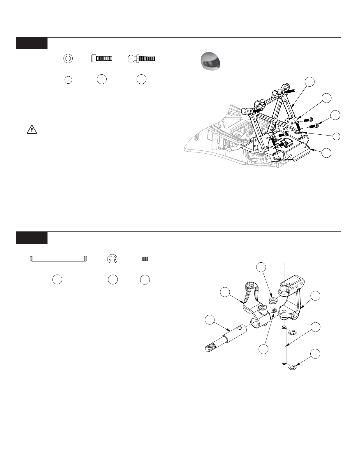
Step 8. Insert a front axle (39) into each of the front spindles [right
(40), left (41)] as shown. The hole in the axle (39) should line up with
the hole in the spindle (40), (41).
Step 9. Attach the right spindle (40) to the right spindle carrier (42) by
aligning the holes in each part and inserting a 1/8" x 1.250" king pin
(44) from the bottom. Do not insert the pin all the way through both
parts yet.
Step 10. Insert a front spindle spacer (45) between the top of the
spindle (40) and the spindle carrier (42) as shown in Figure 18. Once
the spacer (45) is in place, insert the king pin (44) through the spacer
(45) and the top of the spindle carrier (42).
tep 11. Center the king pin (44) and secure it with two 1/8" E-clips (46).
With the king pin (44) still centered, thread a 5-40 setscrew (47) into
the back side of the axle (39) and tighten.
Step 12. Repeat Steps 8-11 for the left spindle (41) and left spindle
carrier (43).
4
4
39
40
45
47
Figure 18
4
4
4
8
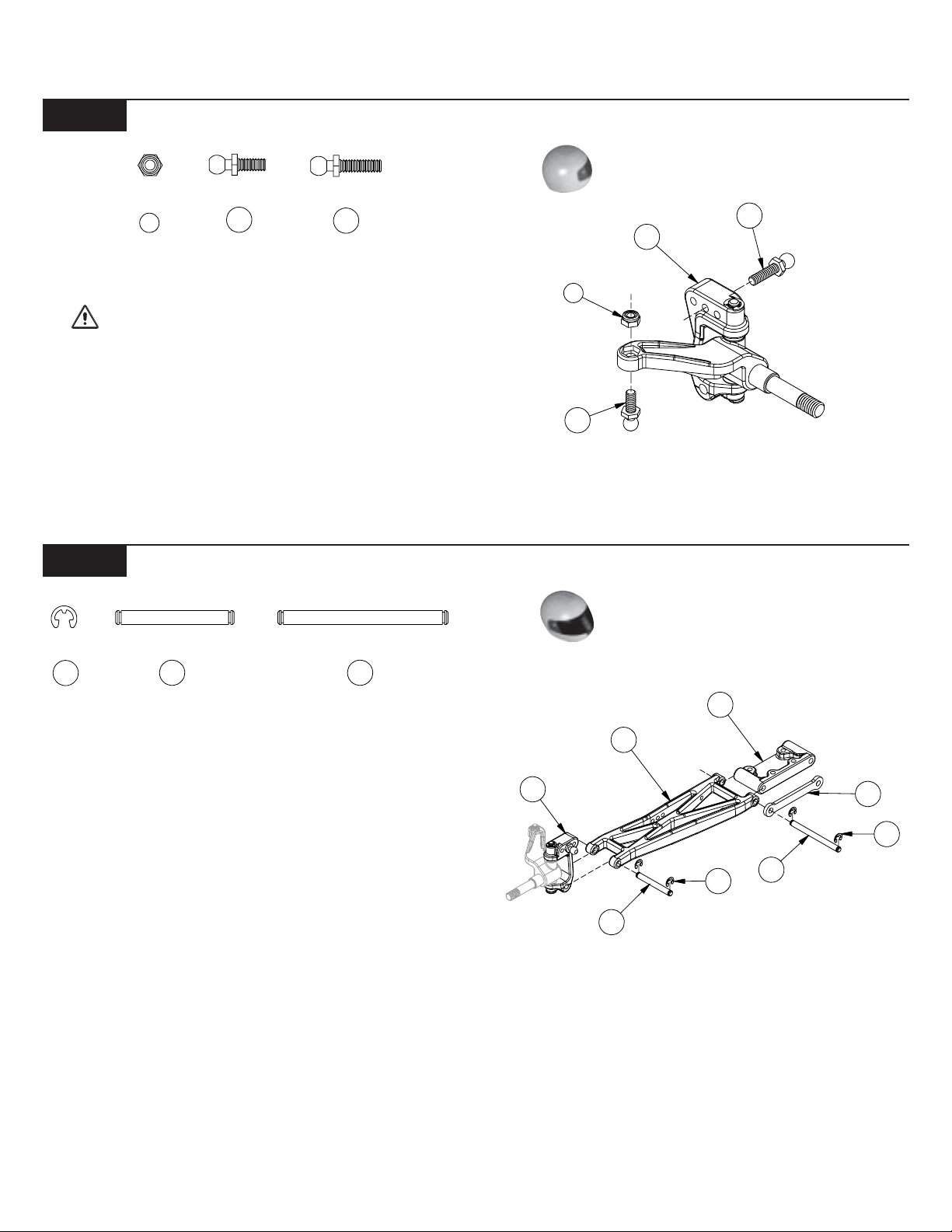
Figure 19
6
6
BAG B (Continued)
7
Step 13. Insert a 3/8" ball stud (38) into the middle hole on top of each
spindle carrier (42), (43) from the front as shown, and tighten.
IMPORTANT NOTE: Do not overtighten the ball studs!
Step 14 . Insert a 4-40 mini locknut (7) into the hex area in the top of
each spindle (40), (41). Thread a 1/4" ball stud (10) into the nut from
the bottom of the spindle (40), (41) and tighten.
10
38
Figure 20
38
42
7
10
Figure 19
4
Step 15. Attach the right spindle and carrier assembly to a front suspension arm (48) as shown in Figure 20. Note that the spindle arm
faces the side of the suspension arm (48) with the shock mount holes
(rear) and the ball stud pointing forward. Line up the holes in the
spindle carrier (42) with the holes in the front arm (48), insert a 1/8“ x
.960" hinge pin (50) and attach a
1/8” E-clip (46) to both sides of the hinge pin (50).
Step 16. Attach the arm (48) to the right side of the front pivot block
(49) by inserting a 1/8" x 1.42" hinge pin (51), from the front, through
the arm (48) and pivot block (49) as shown in Figure 20.
Step 17. Insert a 1/8" E-clip (46) in the groove in the rear of the hinge
pin (51) only .
Step 18. Repeat Steps 15-17 for the left spindle and carrier assembly
and remaining front suspension arm (48).
Step 19. Slide the front hinge pin brace (52) over the front of both
inner hinge pins (51). The E-clip grooves in both hinge pins (51)
should be exposed in front of the brace (52). Secure the brace (52) by
attaching a 1/8" E-clip (46) to the front of each hinge pin (51).
50
51
42
50
48
49
46
Figure 20
52
4
51
9
2
BAG B (Continued)
Figure 21
21
Step 20. Hold the chassis assembly upside down. Place the front
pivot block (49) over the front edge of the front kick plate (14) as
shown in Figure 21. The front lip of the front bulkhead (32) should be
positioned in the space between the front pivot block (49) and the
aluminum hinge pin brace (52).
Step 21. While holding the front suspension assembly in place, position the front bumper (53) on the bottom of the front pivot block (49)
so that the four holes in the bumper (53) are aligned with the four
holes in the pivot block (49). The bumper (53) should be attached as
shown so that the edges curve towards the top of the chassis. Secure
the bumper (53) and pivot block (49) to the front bulkhead (32) and
kick plate (14) by threading four 4-40 x 5/8" flat-head screws (21)
through the bumper and pivot block and tightening.
Figure 22
21
53
49
14
32
Figure 21
54
Step 22. Thread a long plastic rod end (54) onto each end of a 2-1/4"
turnbuckle (55). Tighten both rod ends (54) equally until the rod is the
same length as the rod in Figure 22A. Make two of these camber link
assemblies.
*NOTE: The turnbuckles have right and left hand threads at
opposite ends. This allows the length of the rods to be adjusted
without removing them. Install all turnbuckles with the machined
groove to the left side so all adjustments will be made in the same
direction.
55
Figure 23
Step 23. Place a "foam thing" (56) over the ball studs (38) in each of
the spindle carriers (42), (43) and the ball studs (10) in the front
bulkhead (32). Next, attach one side of a camber link assembly to the
ball stud (10) on the right side of the bulkhead (32). Attach the other
side of the camber link assembly to the ball stud (38) in the spindle
carrier (42).
Step 24. Attach the second camber link assembly to the left side of the
truck.
Tip: Try to mount all of the camber links so that the threads adjust
in the same direction. This allows for much easier adjustments later.
55
54
Figure 22
Figure 22A
3
38
10
10
56
Figure 23
42
10
11
8
40
Figure 24
BAG B (Continued)
54
Step 25. Thread a long plastic rod end (54) onto each end of a 2-1/4"
turnbuckle (55). Tighten both rod ends (54) equally until the rod is the
same length as the rod in Figure 24A. Make two of these tie-rod
assemblies.
55
Figure 25
55
54
Figure 24
Figure 24A
Step 26. Snap one end of a completed tie rod assembly to the ball stud
(11) in the steering idler arm (8). Snap the other end to the ball stud
(10) in the right spindle (40). Attach the other tie rod assembly to the
ball stud in the bottom of the servo saver assembly (8) and the left
spindle (41).
Tip: Once again, assure that all turnbuckles are mounted with the
threads in the same direction for easier adjustment later.
Figure 25
11
9
BAG C
7
57
0
E
3
Figure 26
7
Step 1. Insert a 4-40 mini locknut (7) into the hex area of the diff nut
carrier (57). The thread-locking portion of the nut (7) should be to the
outside.
Figure 26
Figure 27
2
Step 2. Locate the 5/64" Allen wrench (59) supplied with the kit. Place
the diff nut carrier (57), nut side first, over the Allen wrench (59).
Step 3. Slide the #4 washer (23) over the wrench up against the diff
nut carrier (57).
Step 4. Slide the differential coil spring (58) over the wrench so that it
is up against the #4 washer as shown in Figure 27.
Figure 28
Step 5. Insert all of the parts that are stacked on the wrench into the
male outdrive/diff half (60). Line up the tabs on the diff nut carrier (57)
with the slots in the outdrive (60). Press the parts all the way into the
outdrive/diff half (60).
58
23
57
5
Figure 27
6
Figure 29
61
Step 6. Apply a small amount of diff grease (clear) (62) all the way
around the face of the outside ridge of the outdrive/diff half (60).
Attach a diff washer (61) to the outdrive (60) by centering the hole in
the washer (61) over the raised center of the outdrive (60).
*NOTE: Only a small amount of grease is needed, but be sure to
cover the entire face of the ridge on the outdrive.
outdrive/diff halves. Doing so may not allow the washers to mount
flat.
IMPORT ANT NOTE: Do not glue the diff washers to the
Figure 28
61
APPLY
GREAS
HERE
60
Figure 29
12
4
G
5
BAG C (Continued)
5
8
0
6
G
Figure 30
63
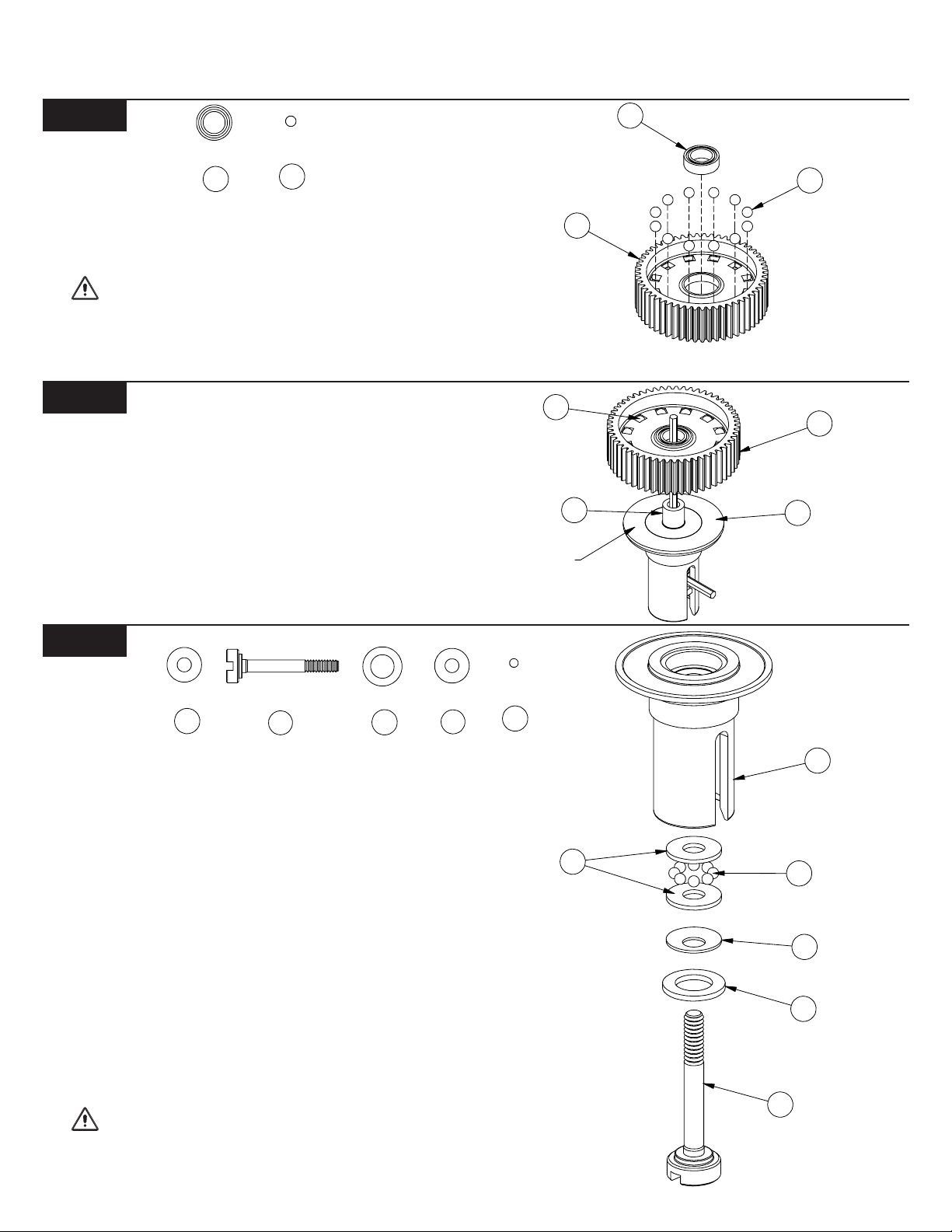
Step 7. Insert a 5mm x 8mm bearing (63) into the center of the diff gear
(64).
Step 8. Press a 3/32" carbide diff ball (65) into each of the small holes
in the diff gear (64).
IMPORTANT NOTE: There are two sets of diff balls in
Bag C. Be certain to use the slightly larger balls that are packaged
alone (12 total) in Figure 30, Step 8. There is a second set of eight 5/
64" balls packaged with washers in the bag. These balls will be used
in Figure 32.
6
Figure 31
Step 9. Apply a fairly heavy coat of clear diff grease (62) to the exposed side of the diff washer (61). Carefully place the diff gear (64)
over the male outdrive (60) so that the diff balls (65) and diff gear (64)
rest against the diff washer (61).
65
REASE
64
60
63
6
Figure 30
6
61
Figure 31
Figure 32
5
Step 10. Locate the diff adjusting screw (67) and place the foam thrust
bearing seal (68) over the shoulder of the screw (67).
Step 11. Place one beveled washer (58) over the diff screw (67) with
the concave surface facing away from the head of the diff screw (67).
Step 12. Place one of the 3mm x 8mm thrust bearing
washers (69) over the diff screw (67).
*NOTE: The thrust bearing washers are packaged in a small
bag along with the eight 5/64" thrust bearing balls.
Step 13. Grease the thrust washer (69) well with white thrust bearing/
assembly grease (71) and place the eight 5/64" thrust bearing balls
(70) on top of the washer (69), around the diff screw (67). Apply more
white thrust bearing/assembly grease (71) to the tops of the thrust
bearing balls (70). Place the second thrust washer (69) over the screw
(67) and against the thrust bearing balls (70).
Step 14. Very carefully insert the diff screw (67), with the thrust bearing assembly installed, into the female outdrive (66). Pull the threaded
end of the diff screw (67) until the thrust bearing assembly rests
against the inside of the outdrive (66).
IMPORT AN T NOTE: Ensure that all eight thrust bearing
balls remain in place between the two washers, around the diff screw .
67
68
69
13
7
69
REASE
Figure 32
6
70
58
68
67
Figure 32
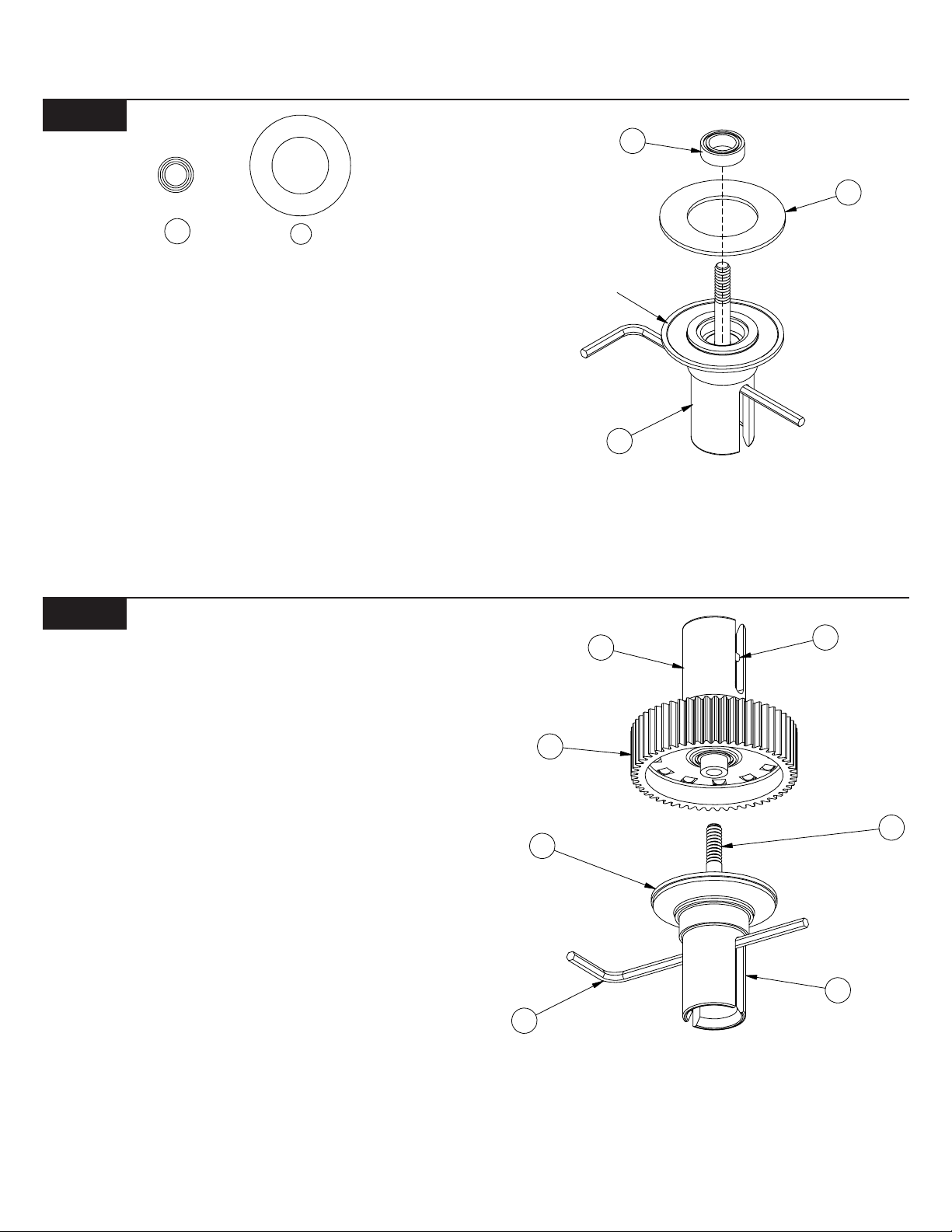
Figure 33
1
G
7
BAG C (Continued)
63
6
63
Step 15. Locate the smallest of the Allen wrenches (59) and place it
through the slot in the outdrive/diff half (66) containing the diff screw
(67). Slide the wrench all the way against the screw (67). By handling
the outdrive/diff half (66) with the wrench
inserted, the diff screw (67) will be held in place while finishing assembly of the differential.
Step 16. Insert a 5mm x 8mm bearing (63) into the female outdrive/diff
half (66). Make sure that the bearing (63) is pushed all the way into
the outdrive (66).
Step 17. Apply a small amount of dif f grease (clear) (62) all the way
around the face of the outside ridge of the outdrive/diff half (66).
Attach a diff washer (61) to the outdrive (66) by centering the hole in
the washer (61) over the raised center of the outdrive (66).
*NOTE: Only a small amount of grease is needed, but be sure to
cover the entire face of the ridge on the outdrive.
61
Figure 34
REASE
60
66
Figure 33
57
Step 18. Apply a fairly heavy coat of clear diff grease (62) to the
exposed side of the diff washer (61).
Step 19. While holding the outdrive/diff half (66) with the Allen wrench
inserted, carefully place the two outdrive/diff halves (60)(66) together .
Step 20. Make sure that the slot in the diff screw (67) is lined up with
the slot in the outdrive/diff half (66) and that the Allen wrench is
inserted in the slot in the diff screw (67).
Step 21. Hold the diff so that the outdrive/diff half (60) with the diff
nut carrier (57) is pointing up. Slowly turn the top diff half clockwise
to thread the diff screw (67) into the 4-40 mini locknut (7) in the diff
nut carrier (57). Thread the two halves together until the screw just
starts to snug up.
*NOTE: If the screw will not thread into the nut, make sure that
the diff nut carrier is pushed all the way into the outdrive/diff half.
Tip: When tightening the diff, tighten the screw a little and then
“work” the diff a little. Then tighten the diff a little more and
“work” the diff again. Continue this until the diff is tight. This
will ensure proper seating of all the parts in the diff
assembly.
Step 22. Tighten the diff until the gear (64) cannot be turned while
both of the outdrives (60)(66) are being held. Final diff
adjustment should be made after completion of the car.
64
6
61
66
59
Figure 34
14
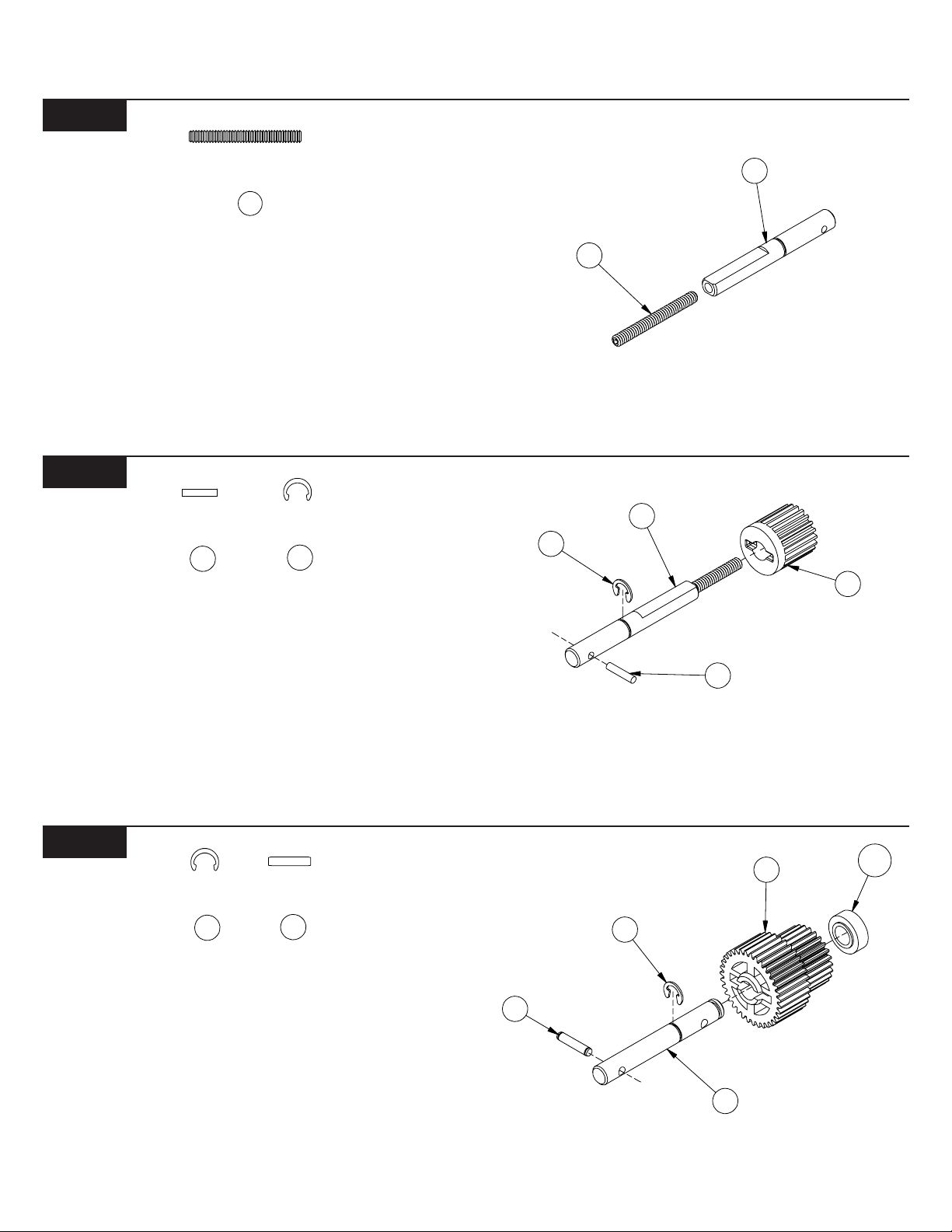
Figure 35
676
4
73
76
74
75
1
BAG C (Continued)
73
72
Step 23. Locate the slipper shaft (73) and thread the 4-40 x 1" setscrew
(72) all the way into the threaded side of the slipper shaft (73). Make
sure that the setscrew (72) is TIGHT!
*NOTE: Some top gear/slipper shaft assemblies may be preassembled from the factory .
Tip: A small amount of liquid thread-lock should be used to help to
hold the setscrew securely in place. If your slipper shaft was preassembled at the factory, thread-lock compound has already been
applied.
Figure 36
7
Step 24. Press the 1/16" x 5/16" pin (74) into the small hole in the
slipper shaft (73) so that it extends evenly from both sides of the shaft
(73).
Step 25. Slide the top gear (75) over the setscrew (72) onto the slipper
shaft (73). Align the groove in the gear (75) with the pin (74) and slide
the gear (75) over the pin (74).
Step 26. Secure the top gear (75) to the shaft (73) by inserting a 3/16"
C-clip (76) into the groove in the slipper shaft (73).
7
72
Figure 35
Figure 37
78
Step 27. Locate the brake shaft (77) and press the .078" x 3/8" spirol
pin (78) into the small hole away from the grooved end of the brake
shaft (77) so that it extends evenly from both sides of the shaft (77).
Step 28. Press the compound gear bushing (181) all the way into the
end of the compund gear (79). Slide the compound gear (79), with the
bushing (181) in place, over the brake shaft (77). Align the groove in
the gear (79) with the pin (78) and slide the gear (79) over the pin (78).
Step 29. Secure the compound gear (79) and bushing (181) to the
shaft (77) by inserting a 3/16" C-clip (76) into the groove in middle of
the brake shaft (77).
Figure 36
79
18
76
78
77
Figure 37
15
3
Figure 38
80
82
81
80
81
83
PRE-TAP
THESE HOLES
BAG C (Continued)
80
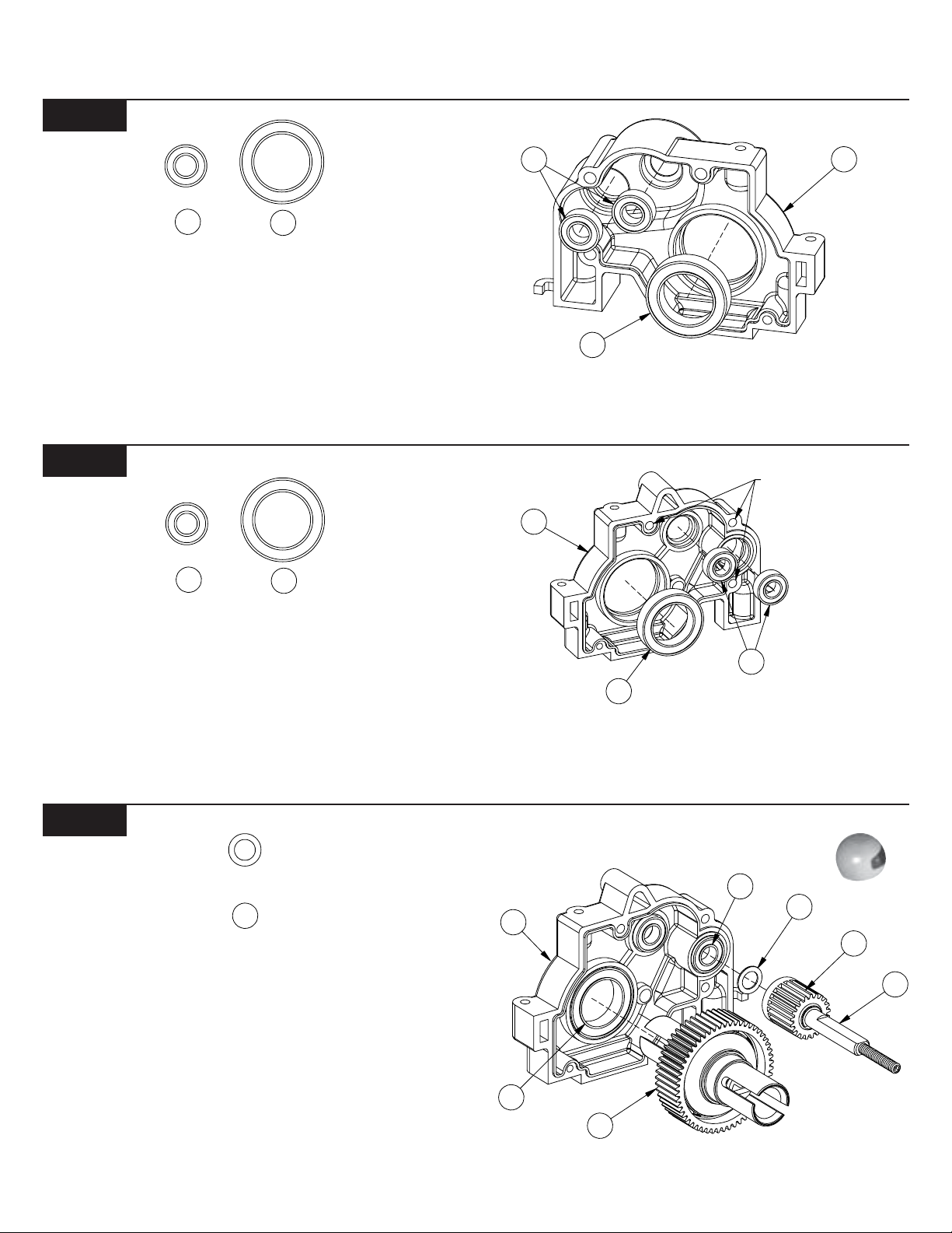
Step 30. Insert two 3/16" x 3/8" sealed bearing (80) into the two top
bearing seats of the right gearbox half (82).
*NOTE: If any of the supplied gearbox bearings only have one
Teflon™ seal(colored, woven looking) in it, position the seal to the
outside of the gearbox half.
Step 31. Insert a 1/2" x 3/4" bearing (81) into the lower
bearing seat of the right gearbox half (82).
81
Figure 39
80
Step 32. Use the short, 4-40 thread-cutting screw included in the
wrench bag to pre-tap the three holes noted in Figure 39. Thread the
screw all the way into and out of each hole.
Step 33. Insert two 3/16" x 3/8" sealed bearing (80) into the two top
bearing seats of the left gearbox half (83).
Step 34. Insert a 1/2" x 3/4" bearing (81) into the lower
bearing seat of the left gearbox half (83).
81
Figure 38
Figure 40
84
Step 35. Slip the 3/16" x .015 shim (84) over the slipper shaft (73) up
against the top gear (75).
Step 36. Insert the slipper shaft (73) into the forward-most bearing
(80) in the left gearbox half (83).
Step 37. Insert the differential assembly into the 1/2" x 3/4" bearing
(81) in the right gearbox half (82). Insert the differential diff nut carrier
(57) side first.
*NOTE: be sure the head of the diff adjusting screw faces the
right side of the gearbox. This will allow easy adjustment while
running your truck.
Figure 39
80
84
83
75
7
81
64
Figure 40
16
BAG C (Continued)
Figure 41
Step 38. Insert the brake shaft (77) through the 3/16" x 3/8" bearing
(80) in the left gearbox half (83), aligning the teeth of the compound
gear (79) with the diff gear (64) and top gear (75) as you do.
80
77
83
79
Figure 41
Figure 42
85
Step 39. Apply a thin coat of white assembly grease (71) along the
inside edge of the left gearbox half (83). This will help seal the gearbox
once it is assembled.
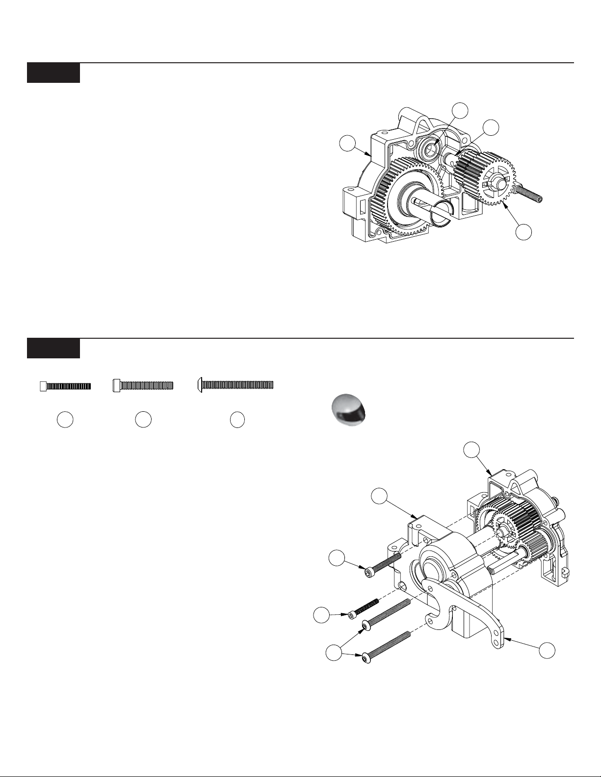
Step 40. Carefully place the right gearbox half (82) over the assembled
left gearbox half (83). Be sure to align each shaft into the bearings in
the right gearbox half (82).
Step 41. Thread the 2-56 x 5/8" cap-head screw (85) into the lower,
rearward hole in the gearbox housing from the right side.
Tip: Be sure you have completed Step 32, and have pre-tapped the
top three holes in the left gearbox before installing the 4-40 x 1-1/
8" buttonhead screws in Step 42.
Step 42. Position the aluminum gearbox brace (88) on the right gearbox half (82) as shown in Figure 42. Thread two 4-40 x 1" button-head
screws (87) through the gearbox brace (88) and into the two holes in
the gearbox housing.
Step 43. Thread the 4-40 x 3/4" cap-head screw (86) into the upper,
middle hole in the gearbox housing from the right side.
86
87
85
86
87
83
82
88
Figure 42
17
 Loading...