

Page 1

OWNER'S
MANUAL
NOTE: Using modified motors with any less than 15 turns of wire exceeds the
capacity of the electronic speed control and voids any warranty.
Carefully read through all instructions to familiarize yourself with the parts, construction
techniques, and tuning tips outlined in this manual. Being able to grasp the overall design of
your new Triple-XT racing truck before beginning the construction process will ensure a smooth
assembly.
T ake your time and p ay close attention to det ail. Keep this manual for future reference.
• Service Information:
Electronics (Motor/Radio/Speed Control)
(877) 504 - 0233
• Chassis (All non-electric) (909) 390-9595
T eam Losi, 4710 E. Guasti Rd., Ontario, CA 91761
www.TeamLosi.com • feedback@TeamLosi.com
P/N 800-0196
Page 2
Page 3

Welcome Team Losi Triple-XT Sport Owner!
Thank you for choosing Team Losi and the Triple-XT Sport off-road racer. This kit benefits from Team Losi’s unequalled winning heritage as well as their World Champion design staff recognized as the leaders in innovative design
and technical excellence. In fact, the Triple-XT platform that this ready-to-run was modeled after has won the ROAR
National Championship the last three years. The long hours of engineering, development, and track testing result in a race
truck that is easier to drive, tune, and enjoy. To ensure trouble free enjoyment of your new Triple-XT Sport we suggest that
you read through these instructions. Also check out the handy tech tips for additional tuning ideas.
Good luck, and thank you for choosing Team Losi.
1. INTRODUCTION
TRIPLE-XT SPORT COMPLETED KIT DIMENSIONS
Length: 16.195" Front Width: 12.725" Rear Width: 12.875" Height: 5.505"
Wheelbase: 11.050" All dimensions at ride height. Weight will vary depending on accessories.
NOTES & SYMBOLS USED
Figure 1
This is a common figure number found at the beginning
of each new illustration throughout the manual.
! Step 1. - Each step throughout the entire manual has a
check box to the left of it. As you complete each step, mark the
box with a check. If you need to take a break and return to building at a later time you will be able to locate the exact step where
you left off.
*NOTE: This is a common note. It is used to call attention to
specific details of a certain step in the assembly.
IMPORTANT NOTE: Even if you are familiar with
Team Losi kits, be sure and pay attention to these notes. They
point out very important details during the assembly process. Do
not ignore these notes!
! This wrench designates a performance tip. These tips
are not necessary, but can improve the performance of your
Triple-XT truck.
In illustrations where it is important to note which
direction parts are facing, a helmet like this one will be included
in the illustration. The helmet will always face the front of the car.
Any reference to the right or left side will relate to the direction of
the helmet.
KIT/MANUAL ORGANIZA TION
The kit is composed of different bags marked A through G. Each
bag contains all of the parts necessary to complete a particular
section of the Triple-XT. Some of these bags have subassembly
bags within them. It is essential that you open only one bag at a
time and follow the correct assembly sequence, otherwise you may
face difficulties in finding the correct part. It is helpful to read
through the instructions for an entire bag prior to beginning assembly. Key numbers (in parenthesis) have been assigned to each
part and remain the same throughout the manual. In some illustrations, parts which have already been installed are not shown
so that the current steps can be illustrated more clearly.
For your convenience, an actual-size hardware identification guide is included with each step. To check a part, hold it
against the silhouette until the correct part is identified. In some
cases extra hardware has been supplied for parts that may be
easy to lose.
The molded parts in the Triple-XT Sport are manufactured
to demanding tolerances. When screws are tightened to the point
of being snug, the parts are held firmly in place. For this reason
it is very important that screws not be overtightened in any of the
plastic parts.
To ensure that parts are not lost during construction, it is
recommended that you work over a towel or mat to prevent parts
from rolling away.
IMPORT ANT SAFETY NOTES
1. Select an area for assembly that is away from the reach of
small children. Some parts in this kit are small and can be swallowed
by children, causing choking and possible internal injury.
2. The shock fluid and greases supplied should be kept out
of childrens' reach. They are not intended for human consumption!
3. Exercise care when using any hand tools, sharp instruments,
or power tools during construction.
4. Carefully read all manufacturers' warnings and cautions for
any glues, chemicals, or paints that may be used for assembly and
operating purposes.
i
Page 4

TOOLS REQUIRED
Team Losi has supplied all necessary Allen wrenches and a special wrench that is needed for assembly and adjustments. The following
common tools will also be required: Needle-nose pliers, regular pliers, hobby knife, scissors or other body cutting/trimming tools.
3/16", 1/4", and 3/8" nut drivers are optional.
RADIO/ELECTRICAL
The XXX-T Sport's radio layout is well proven. Your high-performance R/C center should be consulted regarding specific questions
pertaining to radio/electrical equipment changes.
HARDWARE IDENTIFICATION
When in question, use the hardware identification guide in each step. For screws, the prefix number designates the screw size and
number of threads per inch (i.e., 4-40 is #4 screw with 40 threads per inch). The second number or fraction designates the length of
the screw. For cap-head and button-head screws, this number refers to the length of the threaded portion of the screw. For flat-head
screws, this number refers to the overall length of the screw. Bearings and bushings are referenced by the inside diameter x outside
diameter. Shafts and pins are referred to by diameter x length. Washers are described by inside diameter or the screw size that will
pass through the inside diameter. E-clips are sized by the shaft diameter that they attach to.
MOTORS AND GEARING
The Triple-XT Sport includes an 88-tooth, 48-pitch spur gear. The overall internal drive ratio of the Triple-XT is 2.43:1. The pinion gear
that is used will determine the final drive ratio. To calculate the final drive ratio, first divide the spur gear size by the pinion gear size.
For example, if you are using a 20-tooth pinion gear, you would divide 88 (spur gear size) by 20 (pinion gear size).
tells you that 4.4 is the external drive ratio. Next, multiply the internal drive ratio (2.43) by the external drive ratio (in this case 4.4).
2.43 x 4.4 = 10.692
10.692:1.
Consult your high-performance shop for recommendations to suit your racing style and class. The chart below lists some of the
more common motor types and a recommended initial gearing for that motor. Ratios can be adjusted depending on various track
layouts, tire sizes, and battery types.
. This means that by using a 20-tooth pinion gear with the standard 88-tooth spur gear, the final drive ratio is
88/20 =4.4
. This
RECOMMENDED INITIAL GEARING FOR COMMON MOTORS
TYPE OF MOTOR PINION SPUR
24o Stock 2 0 8 8
15-Turn Modified 19 88
16-Turn Modified 19 88
17-Turn Modified 20 88
TABLE OF CONTENTS
1. INTRODUCTION............................................................i
Completed Kit Dimensions ...........................................i
Notes & Symbols .........................................................i
Kit Manual Organization ...............................................i
Important Safety Notes ................................................i
Tools Required............................................................. ii
3. BAG B ........................................................................3-7
4. BAG C ...................................................................... 8-11
5. BAG D .................................................................... 12-19
6. BAG E .................................................................... 20-23
7. BAG F..........................................................................24
8. BAG G .................................................................... 25-29
Radio/Electrical ........................................................... ii
Hardware Identification ................................................ ii
Recommended Gearing ............................................... ii
2. BAG A ........................................................................ 1-2
Team Losi is continually changing and improving designs; therefore, the actual part may appear slightly different than the illustrated part. Illustrations of parts and assemblies may be
slightly distorted to enhance pertinent details.
9. Checklist Before Y our First Run ................................30
10. Tips From the T eam .............................................. 30-32
11. Spare Parts List .................................................... 33-35
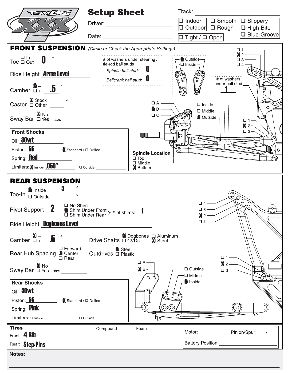
12. Completed Setup Sheet ............................................. 36
ii
 Loading...