

Page 1

INSTRUCTION MANUAL
BEDIENUNGSANLEITUNG
MANUEL D’UTILISATION
MANUALE DI ISTRUZIONI
Before operating this vehicle, please read all printed materials thoroughly.
Horizon Hobby is not responsible for inadvertent errors in this manual.
Page 2
NOTICE
All instructions, warranties and other collateral documents are subject to change at the sole discretion of Horizon Hobby, LLC. For up-to-date product literature, visit
horizonhobby.com and click on the support tab for this product.
Meaning of Special Language
The following terms are used throughout the product literature to indicate various levels of potential harm when operating this product:
NOTICE: Procedures, which if not properly followed, create a possibility of physical property damage AND a little or no possibility of injury.
CAUTION: Procedures, which if not properly followed, create the probability of physical property damage AND a possibility of serious injury.
WARNING: Procedures, which if not properly followed, create the probability of property damage, collateral damage, and serious injury OR create a high probability of
superfi cial injury.
WARNING: Read the ENTIRE instruction manual to become familiar with the features of the product before operating. Failure to operate the product correctly can
result in damage to the product, personal property and cause serious injury.
This is a sophisticated hobby product. It must be operated with caution and common sense and requires some basic mechanical ability. Failure to operate this Product in a safe
and responsible manner could result in injury or damage to the product or other property. This product is not intended for use by children without direct adult supervision. Do
not attempt disassembly, use with incompatible components or augment product in any way without the approval of Horizon Hobby, LLC. This manual contains instructions for
safety, operation and maintenance. It is essential to read and follow all the instructions and warnings in the manual, prior to assembly, setup or use, in order to operate correctly
and avoid damage or serious injury.
AGE RECOMMENDATION: NOT FOR CHILDREN UNDER 14 YEARS. THIS IS NOT A TOY.
Register your Losi Product Online
Register your vehicle now and be the fi rst to fi nd out about the latest option parts, product updates and more. Click on the Support tab at WWW.LOSI.COM and follow the
product registration link to stay connected.
General Safety Precautions and Guidelines
WARNING: This vehicle is only intended for advanced RC drivers capable
of operating large-scale model vehicles.
WARNING: Failure to follow all instructions can lead to damage to your
vehicle, property damage and bodily injury or death.
CAUTION: If you make changes or adjustments not shown in the instruction
manual, your vehicle may be damaged. To prevent any serious
personal injury and/or damage to property, please be responsible when
operating all remote controlled models.
This model is controlled by a radio signal subject to interference from many sources
outside your control. This interference may cause momentary loss of control, so it
is advisable to always keep some distance in all directions around your model as a
safety margin to avoid collisions.
• Always ensure all screws and nuts are tightened.
• Always carefully follow the directions and warnings for this and any optional support
• Always keep all chemicals, small parts and anything electrical out of the reach of
• Always ensure the failsafe is properly set during binding.
• Always operate your model in an open area away from cars, traffi c and people.
• When operating this vehicle, always keep it at least 20 feet from spectators,
• Never run your vehicle through deep water that will submerge the vehicle.
• Never run your model in a public street where damage can occur.
• Never run your model with low transmitter batteries.
• When fi nished operating, always power off the engine fi rst, then the receiver, then the
• Always perform maintenance on the vehicle after each and every use. Due to engine
Li-Po Charger Safety Precautions and Warnings
• Never leave the charger and battery unattended during use.
• Never attempt to charge dead, damaged or wet battery packs.
• Never attempt to charge a battery pack containing different types of batteries.
• Never allow minors to charge battery packs.
• Never charge batteries in extremely hot or cold places or place in direct sunlight.
• Never charge a battery if the cable has been pinched or shorted.
• Never connect more than one battery pack to this charger at a time.
• Never connect the charger if the power cable has been pinched or shorted.
• Never attempt to dismantle the charger or use a damaged charger.
• Never reverse the positive and negative terminals.
• Always use only rechargeable batteries designed for use with this type of
charger.
• Always inspect the battery before charging.
• Always keep the battery away from any material that could be affected by heat.
• Always monitor the charging area and have a fi re extinguisher available at all
times.
• Always end the charging process if the battery becomes hot to the touch or
• Always disconnect the battery after charging, and let the charger cool between
• Always terminate all processes and contact Horizon Hobby if the product
which can lead to user injury or property damage. Please contact Horizon Hobby or
an authorized retailer with compatibility questions.
equipment.
children.
especially small children.
transmitter.
vibration, all screws and nuts will need to be checked to ensure they are tight.
starts to change form (swell) during the charge process.
charges.
malfunctions.
WARNING: Never leave the charger unattended, exceed maximum charge
rate, charge with non-approved batteries or charge batteries in the wrong
mode. Failure to comply may result in excessive heat, fi re and serious injury.
CAUTION: Always ensure the battery you are charging meets the
specifi cations of this charger and that the charger settings are correct. Not
doing so can result in excessive heat and other related product malfunctions,
2
EN
LOSI LST XXL 2 • INSTRUCTION MANUAL
Page 3
Water-resistant Vehicle with Waterproof Electronics
Your new Horizon Hobby vehicle has been designed and built with a combination of
waterproof and water-resistant components to allow you to operate the product in
many “wet conditions”, including puddles, creeks, wet grass, snow and even rain.
While the entire vehicle is highly water-resistant, it is not completely waterproof
and your vehicle should NOT be treated like a submarine. The various electronic
components used in the vehicle, such as the servo(s) and receiver are waterproof,
however, most of the mechanical components are water-resistant and should not be
submerged.
Metal parts, including the bearings, hinge pins, screws and nuts, as well as the
contacts in the electrical cables, will be susceptible to corrosion if additional
maintenance is not performed after running in wet conditions. To maximize the longterm performance of your vehicle and to keep the warranty intact, the procedures
described in the “Wet Conditions Maintenance” section below must be performed
regularly if you choose to run in wet conditions. If you are not willing to perform the
additional care and maintenance required, then you should not operate the vehicle in
those conditions.
CAUTION: Failure to exercise caution while using this product and
complying with the following precautions could result in product
malfunction and/or void the warranty.
Wet Conditions Maintenance
• Remove the battery pack(s) and dry the contacts. If you have an air compressor
or a can of compressed air, blow out any water that may be inside the recessed
connector housing.
• Remove the tires/wheels from the vehicle and gently rinse the mud and dirt off with
a garden hose. Avoid rinsing the bearings and transmission.
NOTICE: Never use a pressure washer to clean your vehicle.
• Use an air compressor or a can of compressed air to dry the vehicle and help
remove any water that may have gotten into small crevices or corners.
• Spray the bearings, drive train, fasteners and other metal parts with a waterdisplacing light oil or lubricant.
GENERAL PRECAUTIONS
• Read through the wet conditions maintenance procedures and make sure that you
have all the tools you will need to properly maintain your vehicle.
• Not all batteries can be used in wet conditions. Consult the battery manufacturer
before use. Caution should be taken when using Li-Po batteries in wet conditions.
• Most transmitters are not water-resistant. Consult your transmitter’s manual or the
manufacturer before operation.
• Never operate your transmitter or vehicle where lightning may be present.
• Do not operate your vehicle where it could come in contact with salt water (ocean
water or water on salt-covered roads), contaminated or polluted water. Salt water is
very conductive and highly corrosive, so use caution.
• While the air fi lter assembly can be designed to limit or restrict water ingestion into
the engine, no air fi lter is completely waterproof. If too much water is ingested into
the engine, severe damage to the engine may result.
• Do not expose your engine to rapid changes in temperature. These engines
tend to operate at temperatures between 200–250°F (93–121°C) in normal
operating conditions. If the engine is exposed to cold water while operating at this
temperature, there is a risk of “thermal shock”, which could cause undue stress on
the engine and a shortened engine lifespan.
• Driving in wet conditions can reduce the life of the engine. The additional
resistance of operating in water causes excess strain. Alter the gear ratio by using
a smaller pinion or larger spur gear. This will reduce the load on the engine (and
engine temperatures) when running in mud, deeper puddles, or any wet conditions
that will increase stress on the engine for an extended period of time.
• Let the vehicle air dry before you store it. Water (and oil) may continue to drip for a
few hours.
• Increase the frequency of disassembly, inspection and lubrication of the following:
• Front and rear axle hub assembly bearings.
• All transmission cases, gears and differentials.
• Engine air fi lter element.
• Engine clutch assembly, including shoes and bearings.
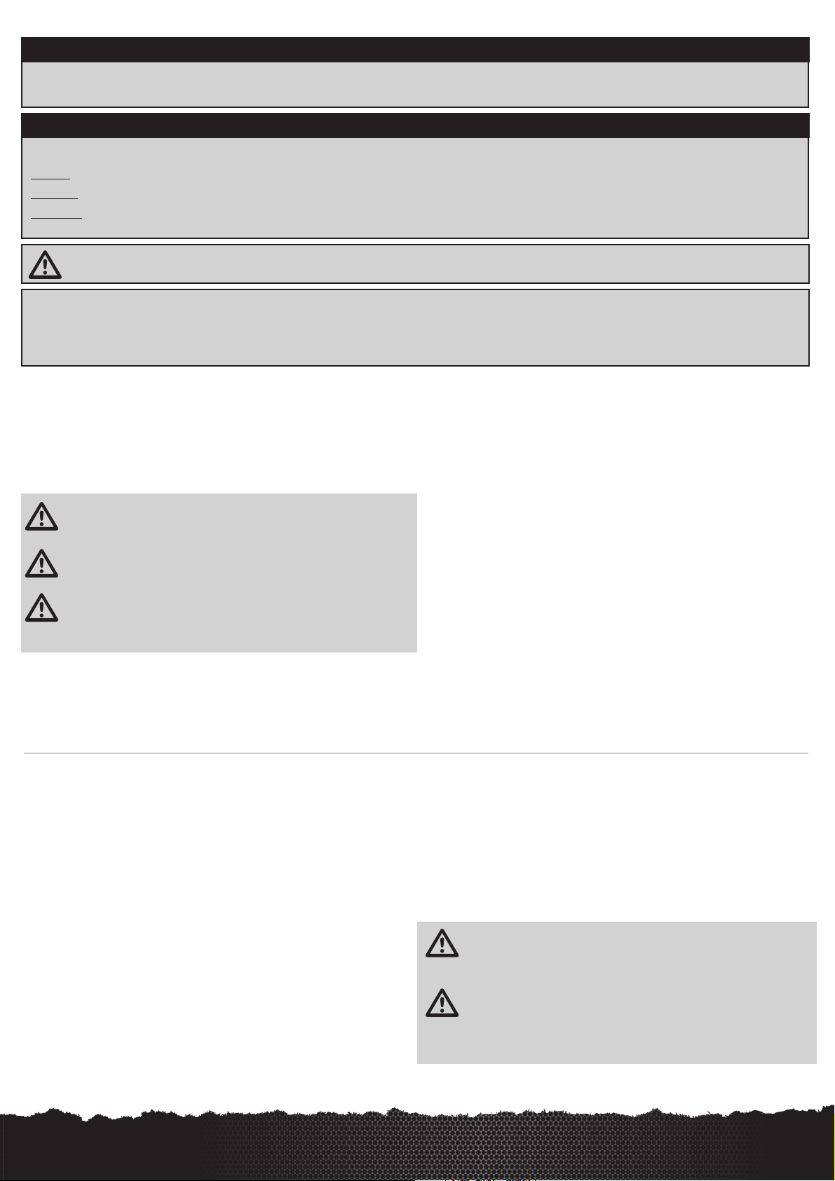
Components
• 1/8-Scale LST XXL™ 2 Monster Truck
• Spektrum
• Dynamite
• Spektrum High-Torque Servo
• 4 AA batteries (for transmitter)
• Dynamite 7.4V 2000mAh Li-Po receiver pack.
• Dynamite Spin-Start handheld Starter
LOSI LST XXL 2 • INSTRUCTION MANUAL
™
DX2E 2.4GHz DSM® Radio System
®
.31 Gasoline Engine
Tools Included
• Wheel wrench
• Four (4) Hex “L” Wrench Set: .050-inch, 1/16-inch, 5/64-inch and 3/32-inch
• Shock Bottom wrench
• Turnbuckle/Shock Top wrench
Needed to Complete
• Gasoline
• 500cc Fuel Bottle (DNY2003)
• 7.2V battery and charger for the Spin-Start (included)
• Small fl at blade and Phillips screwdrivers (DYN3093 and DYN3048)
• Needle-nose pliers
• Quality .050-inch, 1/16-inch, 5/64-inch, 3/32-inch, 1.5mm and 2.5mm hex
(Allen) drivers (DYN2950)
Use only Dynamite
can cause damage to the small screws and parts used on this type of model.
tools or other high-quality tools. Use of inexpensive tools
EN
3
Page 4
Charging the Receiver Battery Pack
Dynamite 7.4V 2000mAh Li-Po receiver pack.
The Dynamite 2S Li-Po battery pack features a balancing lead that allows you
to safely charge your battery pack when used with a Li-Po balancing charger.
1. Remove the LiPo receiver battery pack from the battery box and disconnect the
red JST connector.
2. Connect the LiPo battery charger to an AC power outlet.
3. Refer to manufacturers battery charging directions.
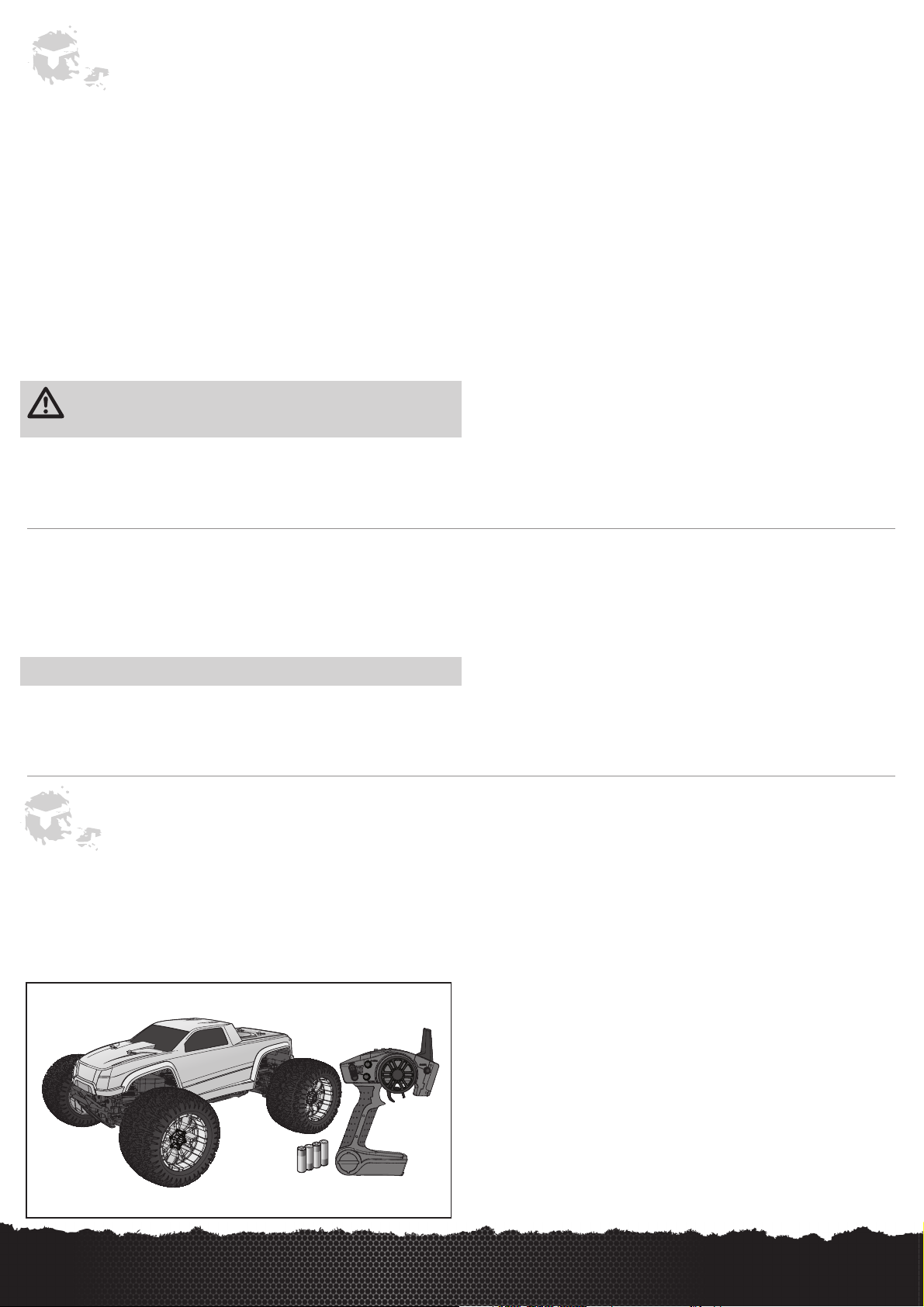
Installing the Receiver Battery in the Battery Box
1. Connect the fully charged LiPo battery pack to the red JST connector
in the battery box.
2. Place the battery box cover on the battery box.
Spektrum DX2E Radio System
For more information on the transmitter, go to www.spektrumrc.com and click on the support tab
3
to find the full manual for the DX2E transmitter.
6
5
4
7
8
1
2
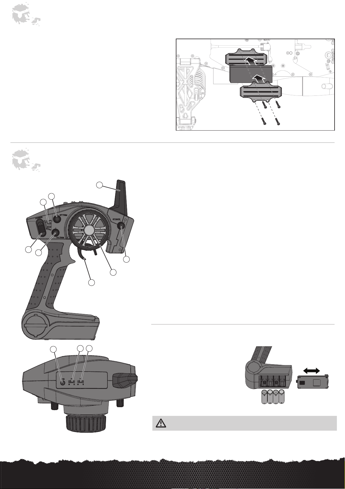
1. Steering Wheel controls direction (left/right) of the model.
2. Throttle Trigger controls speed.
3. Antenna transmits the signal to the model.
4. ON/OFF Switch turns the power ON/OFF for the transmitter.
5. Indicator Lights
• Solid green light indicates adequate battery power.
• Flashing green light indicates the battery voltage is critically low. Replace batteries.
6. ST. Trim adjusts the “hands off” direction of the model.
7. TH. Trim adjusts the engine speed to idle at neutral.
8. ST. Rate Adjusts the AVC sensitivity.
9. BIND/R.O.S.S. button puts the transmitter into Bind Mode and starts or stops the engine
using R.O.S.S. (the LST XXL 2 does NOT use ROSS)
10. ST. REV reverses the function of the steering when the wheel is turned left or right.
11. TH. REV reverses the throttle control when pulled back or pushed forward.
Installing the Transmitter Batteries
10
9
11
1. Push in the battery cover a small amount
to release the retaining tab, then remove
the cover.
2. Install 4 AA batteries, taking care to align
battery polarity to the diagram in the
transmitter’s battery case.
3. Carefully reinstall the battery cover by
aligning the tabs with the slots on the
transmitter.
CAUTION: NEVER remove the transmitter batteries while the vehicle is powered on, as
loss of control, property damage or injury may result.
4
EN
LOSI LST XXL 2 • INSTRUCTION MANUAL
Page 5
AVC – Active Vehicle Control
The Spektrum™ AVC™ stabilization system adds a whole new level of control to
your RC driving experience. AVC technology utilizes sensors to adjust steering and
throttle output, providing you with a more stable and controlled driving experience.
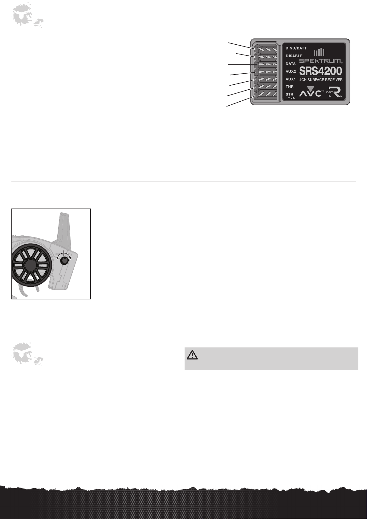
Spektrum SRS4200
The Spektrum SRS4200 receiver features AVC technology that responds similar to
traction control in full-scale vehicles. In addition to traction control, AVC technology
also increases steering stability during high speed driving or while driving over rough
terrain. As you increase the AVC sensitivity, the system increases steering stability
and traction control, similar to reducing the amount of steering rate in a computer
transmitter. Reducing the sensitivity value increases the amount of steering control
from the transmitter. The SRS4200 receiver also enables you to quickly turn AVC on
or off if you participate in organized racing.
IMPORTANT: You must use digital servos with the SRS4200 receiver. Using analog
servos will reduce the performance of the system and may cause analog servos to
overheat.
1. BIND
2. DISABLE
3. DATA
4. AUX 2
5. AUX 1
6. THR
7. STR
Adjusting AVC Sensitivity
The ST. RATE dial adjusts the sensitivity, or stability, value in the receiver. If you increase the sensitivity, the AVC system becomes
more sensitive to the vehicle drifting left or right. You would use maximum sensitivity during high speed driving or drag racing, when
you want the vehicle to stay in a straight line. As the sensitivity value increases, the amount of steering travel decreases.
Turn the ST. RATE knob counter-clockwise to reduce the sensitivity.
Turn the ST. RATE knob clockwise to increase the sensitivity.
IMPORTANT: The ST. RATE knob will only adjust the sensitivity when the transmitter is bound to a DSMR receiver. When the
transmitter is bound to a DSM, DSM2 or DSM Marine receiver, the ST. RATE knob controls the steering dual rate.
Driving Precautions
• Maintain sight of the vehicle at all times.
• Inspect the vehicle for loose wheel hardware.
• Inspect the steering assembly for any loose hardware. Driving the vehicle offroad can cause fasteners to loosen over time.
• Stop driving the vehicle when you notice a lack of power. Driving the vehicle
when the battery is discharged can cause the receiver to power off. You may
lose control of the vehicle.
CAUTION: Do not discharge a LiPo battery below 3V per cell. Batteries discharged
to a voltage lower than the lowest approved voltage may become damaged,
resulting in loss of performance and potential fi re when batteries are charged.
• Do not apply the throttle in forward or reverse if the vehicle is stuck. Applying
throttle in this instance can damage the engine.
• Let the engine cool to ambiant temperature between runs.
LOSI LST XXL 2 • INSTRUCTION MANUAL
EN
5
Page 6
Fuel Safety and Use Instructions
• Always observe all warnings, precautionary statements and instructions supplied
by the fuel manufacturer/provider.
• Fuel is a fire accelerant. Never operate your vehicle near open flames. Never
smoke while operating your vehicle or while handling fuel.
• Always only use a mixture of gasoline and two-cycle oil for fuel. Do not use glow
(nitro) fuel.
• Always use caution when handling gasoline.
• Always run your model engine in a well-ventilated area. Model engines produce
harmful carbon monoxide fumes.
• Always drain your engine after you have finished running your vehicle. Do not store
the vehicle with fuel in the gas tank.
• Never handle model engines and mufflers until they have had time to cool. They
become extremely hot when in use.
• Always store your fuel in a safe place well away from sparks, heat or anything that
can ignite.
Fuel Mixing Precautions and Guidelines
• Only use gasoline mixed with two-cycle engine oil.
• Only use Dynamite Pre-Mix Two-Cycle Engine Oil (DYNE4105).
Do not use any other kind of oil.
• Always use 92–98 Octane RON (Europe) and 91–93 Octane AKI (US) gasoline.
• Always blend gasoline with two-cycle engine oil at a 14:1 ratio.
• Never use a 40:1, 32:1 or 25:1 gas-oil ratio.
• Never use glow (nitro) fuel.
• Always ensure that gasoline and fuel are stored in a clearly marked container well
away from the reach of children.
• Always mix and store your fuel safely in a sealed, water-resistant container
specifically made for gasoline.
• Always store fuel in a cool, dry location. Do not allow fuel containers to come in
direct contact with concrete, as the fuel may absorb moisture.
• Always responsibly discard fuel if there is condensation and/or water inside the
fuel container.
• Never allow fuel to come into contact with eyes or mouth.Gasoline and other fuels
used in model engines are poisonous.
• Never return unused fuel from the fuel tank back into the fuel container.
• Contact your local waste disposal authorities for more information about discarding
fuel waste responsibly.
Gasoline
14 : 1
2-Cycle
Engine Oil
Gasoline : 2-Cycle Engine Oil
1 gallon : 9.5 fl oz
1/2 gallon : 4.8 fl oz
1/4 gallon : 2.4 fl oz
4 liters : 282 ml
2 liters : 141 ml
1 liter : 71 ml
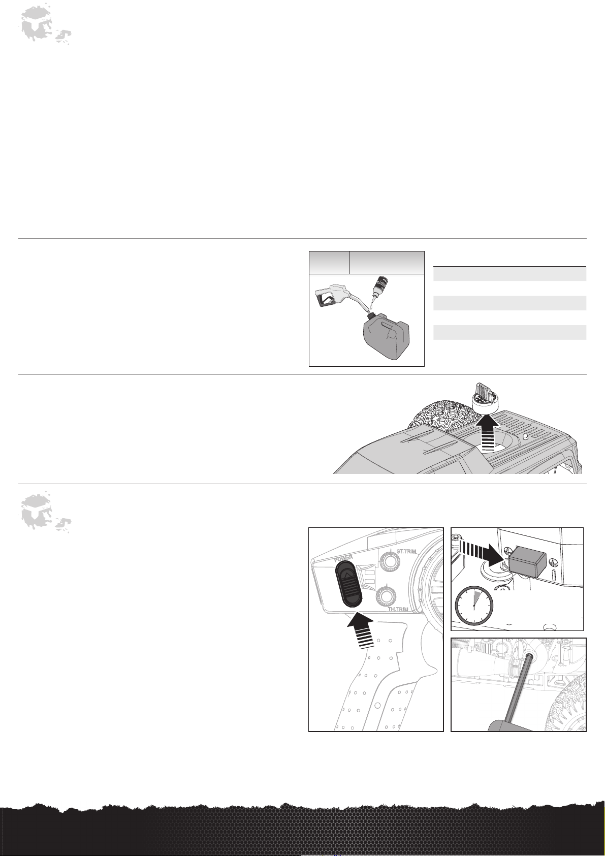
Fueling the Truck
Remove the fuel tank cap and fill the fuel tank. Tighten the fuel tank cap securely
back in place.
NOTICE: Running a loose fuel tank cap will cause inconsistency and high idle speed.
Vehicle Starting and Running with AVC
1. Center the ST. TRIM and TH. TRIM dials on the transmitter.
2. Fill the fuel tank with 2-stroke gasoline (14:1 gasoline:oil ratio).
3. Power on the transmitter.
4. Power on the vehicle. The vehicle and receiver MUST remain motionless for at
least 5 seconds.
5. Place the machined end of the starter shaft into the matching hex socket in the
back-plate of the engine.
6. Holding the starter securely, press on the switch button and the engine should
turn over and start up.
Follow the engine break-in procedure before attempting any racing or highperformance operation. Use caution when adding fuel while the engine is running. Do
not over fi ll or spill fuel outside the tank.
IMPORTANT: Always make sure the vehicle is motionless and on a level surface
before powering on the vehicle. Each time you power on the vehicle, the Spektrum
SRS4200 receiver automatically detects the receiver position (or orientation). The
vehicle must remain motionless and level until the receiver calibration is complete
(normally 5-10 seconds after powering on the vehicle). Moving the vehicle or not
placing it on a surface will reduce the performance of the receiver.
Keep immobile for
5-10 seconds
6
EN
LOSI LST XXL 2 • INSTRUCTION MANUAL
Page 7
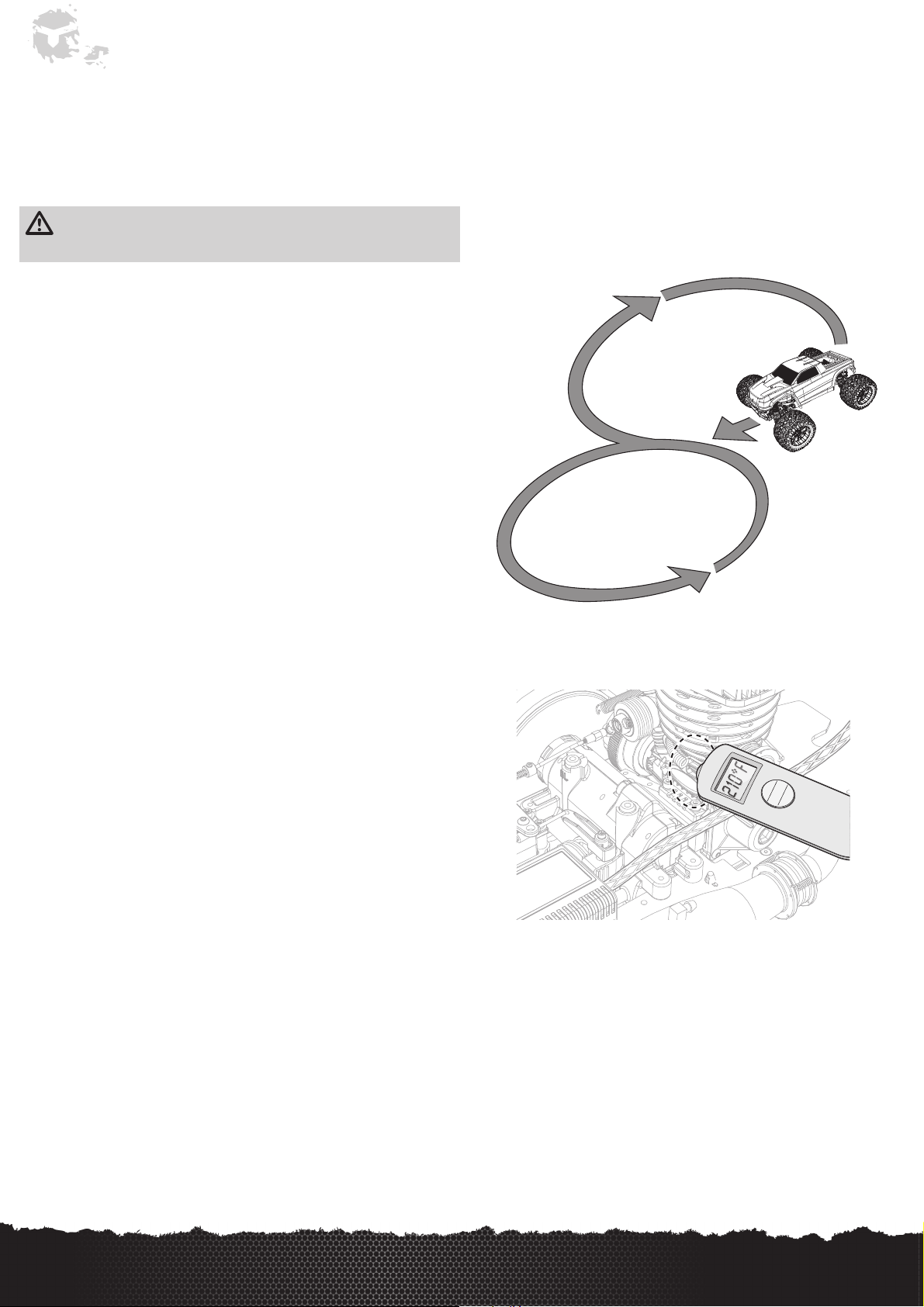
Engine Break-In
Breaking in your new engine is critical for proper performance. Failure to follow the break-in procedures can cause engine damage and shortened engine life. Always use a
14:1 gasoline:oil mixture during the break-in process and when running the engine.
If you change fuel or run in dramatically different environments (hot/cold, high/low elevation, etc.) you will need to adjust the carburetor needles to prevent overheating and
maintain proper performance. Never allow the engine to rev freely with the wheels off the ground.
Use the optional Dynamite Pro Temp Gun with Laser Sight (DYNP2000) to check engine temperatures.
Break-In Procedure:
CAUTION: You must complete the break-in process on a smooth surface, such
as pavement or concrete. Do not drive the vehicle on dirt or grass during the
break-in process; doing so will damage the engine.
Priming the Carburetor
Before turning on the vehicle, install the spin-start into the side of the engine. Hold
fi nger over exhaust tip and press spin-start button for one second to prime the
carburetor. Stop spin-start. With spin-start still installed into the side of the engine,
remove fi nger from exhaust tip and press spin-start button for two seconds.
NOTICE: Unlike nitro engines, do not allow the gasoline engine to idle for several
tanks. Allowing the engine to idle prevents the engine from reaching operating
temperature.
Fuel Tank #1:
1. Drive the vehicle in a fi gure 8 for the fi rst half tank of fuel. Keep the throttle
position between 1/4 – 3/4 throttle. Do not exceed ¾ throttle.
2. During the second half of the tank, move the throttle position between ¼ and full
throttle. Do not hold full throttle for more than one second.
Engine temperature: Do not exceed
Fuel Tank #2: Move the throttle position between ¼ and full throttle. Do not hold full
throttle for more than one second.
Engine temperature: Do not exceed
Fuel Tank #3:
1. For the fi rst half tank of fuel, move the throttle position between ¼ and full
throttle. Do not hold full throttle for more than one second.
2. Lean the high speed needle 2-3 hours when the fuel level reaches ½ tank.
3. For the second half of the tank, move the throttle position between ¼ and full
throttle. Do not hold full throttle for more than two seconds.
Engine temperature: Do not exceed
Fuel Tank #4:
1. For the fi rst half tank of fuel, move the throttle position between ¼ and full
throttle. Do not hold full throttle for more than two seconds.
2. Lean the high speed needle 1-2 hours when the fuel level reaches ½ tank.
3. For the second half of the tank, move the throttle position between ¼ and full
throttle. Do not hold full throttle for more than three seconds.
Engine temperature: Do not exceed 230ºF (
195ºF (
210ºF (
225ºF (
)
90ºC
)
99ºC
107ºC
110ºC
)
)
Notice: Engine temperatures are measure on the side of the
engine block and not at the top of the head like a traditional
nitro engine.
Fuel Tanks #5-8:
At the end of Tank #4, the vehicle is ready to run on dirt surfaces. Maintain the
same carburetor settings that were used during Tank #4 through Tank #8. After
8 tanks of fuel, you can tune the engine for peak performance.
Engine temperature: Never exceed
250ºF (
121ºC
)
LOSI LST XXL 2 • INSTRUCTION MANUAL
EN
7
Page 8
Vehicle Tuning
After the engine is broken in, you can tune it for optimum performance. When tuning, it is critical that you be cautious of overheating as severe damage and pre-mature wear
can occur. You want to make all carburetor adjustments in “one hour” increments.
Before making adjustments:
• Ensure there are no leaks or obstructions in the fuel tank, fuel tubing or the
carburetor. Any faults can affect engine operation and tuning.
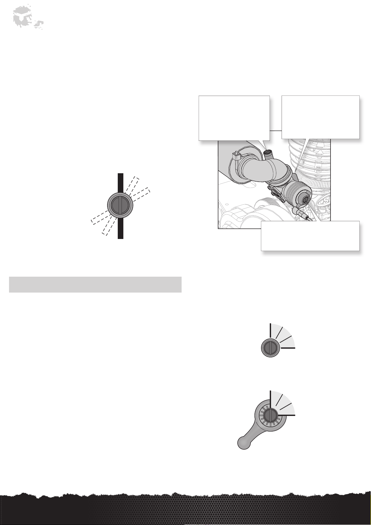
• The carburetor needle is very sensitive. Adjusting the needle even 1/12 of a turn is
a significant change. Be careful when making adjustments.
Idle Needle (left, rear of
carburetor). The engine includes an
idle needle for carburetor function,
however it is not used for engine
tuning. DO NOT ADJUST THE IDLE
NEEDLE.
Factory Needle Settings:
Low Speed Needle: 30 hours from the bottom
High Speed Needle: 18 hours from the bottom
Carb Adjustments:
Make all carburetor adjustments in
one-hour increments.
Imagine the slot in the needle is the
hour hand on a clock. Adjust it as
though you were moving the hour
hand from one hour to the next or
previous one.
High-Speed Needle (top, left
side). Close the high-speed
needle by turning it clockwise
until it stops, then turn it
counterclockwise 18 hours out
(open).
1 hour
2 hour
Low-Speed Needle (on the right side). Close
the low-speed needle by turning it clockwise
until it stops, then turn it counterclockwise
30 hours out (open).
NOTICE: When making adjustments, only turn the needle 1/12 turn at a time.
Adjusting the High Speed Needle
Turn the high-speed needle until you achieve the ideal engine temperature and
amount of exhaust smoke. The engine should have a noticeable smoke trail during
initial acceleration and fade to a minor smoke trail when the engine reaches full
throttle.
If the engine exceeds proper running temperature, 240F (116 C), richen the highspeed needle immediately. If the engine temperature is very low considering normal
running temperature, then lean the high-speed needle.
If the high-speed needle is too lean, it will cause a high idle speed.
Adjusting the Low Speed Needle-Idle Adjustment
Turn the low-speed needle to adjust the engine idle speed. Once you have achieved
a proper idle speed, you can turn the low-speed needle by one hour in either
direction to reach the optimal engine performance. Leaning (turn in) produces a
higher idle speed. Richening (turn out) produces a lower idle speed.
8
EN
LOSI LST XXL 2 • INSTRUCTION MANUAL
Page 9
A
s
Vehicle Tuning
Adjusting the Slipper
The slipper is a key component of the drivetrain that is designed to help absorb
sudden or large impacts that would otherwise stress various drivetrain parts. You
should never run the LST XXL 2 vehicle with the slipper locked (completely tight).
The slipper can also be used as a tuning aid for extremely slick conditions. To
easily adjust the slipper, remove the plug from the gear cover. Start by turning
the 1/4-inch adjustment nut clockwise (tighten) until it gets tight and the spring is
compressed. Do not overtighten as you will strip the nut. Now turn the adjustment
nut counterclockwise (loosen) one full turn. This should be a good overall setting.
2-Speed Adjustment
Although pre-adjusted at the factory, the two-speed can be adjusted to shift at the
point that suits you best. Under normal circumstances, it should shift slightly before
the engine reaches maximum power. The actual distance traveled will vary with
the gear ratio and tune of the engine. There are two adjustment screws (see fig 1)
that must be changed evenly for the two-speed to function correctly. Turning these
clockwise will make it shift later and require the engine to rev higher. Turning them
counterclockwise will make it shift earlier and require less engine speed. If you
should get lost adjusting the two-speed, start over at the factory setting by lightly
bottoming out the adjustment screws and then backing them out five full turns. The
procedure for adjusting the two-speed is as follows.
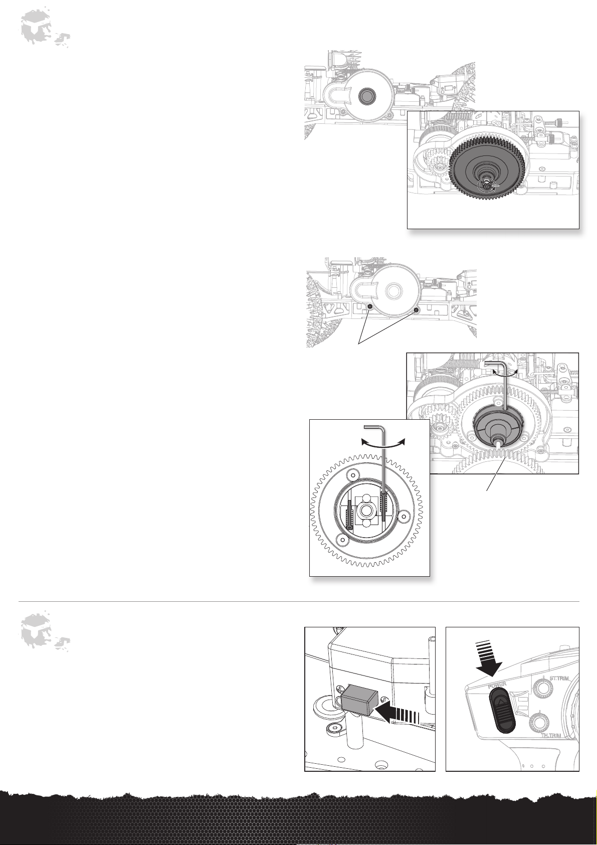
• Remove the gear cover.
• Turn the spur gears until the adjustment hole is visible in the bell housing between
the large and small spur gears.
• Hold the small spur gear and, using your thumb, rotate the slipper forward until
you can see the head of one of the adjustment screws.
• Use a 5/64 Allen wrench to make your adjustment in 1/2-turn increments. Use the
bent leg of the wrench as your guide.
• Turn the slipper forward 1/2 rotation to adjust the other adjustment screw like the
first.
(Remember to always adjust BOTH screws the same amount)
• Test drive the model to check the new shift point and replace the gear cover if
satisfied.
• Never run your model without the gear cover, as it is dangerous and gear damage
will occur!
Remove 2 screws to
remove gear cover.
Fig 1
Later
Always adjust BOTH adjustment
screws evenly
Sooner
Gear cover removed for
illustration purposes.
Turn one full turn out
Outer spur gear removed for illustration
purposes.
Turning Off the Truck
1. To turn off the truck, simply move the truck's receiver power switch to the off
position. This will eliminate power to the CDI and will turn off the engine.
2. Power off the transmitter.
LOSI LST XXL 2 • INSTRUCTION MANUAL
1. 2.
EN
9
Page 10

Troubleshooting Guide
Possible Cause Solution
ENGINE DOES NOT START
Out of fuel Refi ll the tank and follow starting instructions.
Engine fl ooded Remove the spark plug. Roto-start for 3 to 5 seconds. Replace and test
Air fi lter is clogged Check and replace if necessary
Fuel mixture is old or bad Mix fresh fuel per instructions
Spark plug is not working Check the spark plug and ignition coil and replace if necessary
Throttle servo failed/Setup is wrong Check servo operation. Set it to neutral and reset the linkage according
Carburetor is incorrectly adjusted Return the carburetor to the factory settings and retune if necessary
Piston and cylinder is worn Check the piston and cylinder for wear or damage and replace if necessary
Vehicle's power switch is not in the on
position
ENGINE STARTS THEN STALLS
Out of fuel Refi ll the tank and follow starting instructions
Air fi lter is clogged Check and replace if necessary
Engine may be overheated Let the engine cool. Reset the carburetor to factory settings and restart
Engine idle is too low Follow the instructions to increase idle speed
Carburetor is incorrectly adjusted Return the carburetor to the factory settings and retune if necessary
Clutch is slipping or locked-up Check the clutch for worn/broken lining or spring. Also check clutch
Fuel mixture is old or bad Mix fresh fuel per instructions
Throttle servo is improperly set up Set the servo to neutral and reset the linkage according to radio and model
Drivetrain is not functioning properly Check the drivetrain for smooth operation/damage
to your radio and model manufacturer's specifi cations
Locate the power switch on the side of the receiver box and switch to ON
position
bearings and ensure free rotation
manufacturer's specifi cations
ENGINE IS RUNNING, BUT VEHICLE DOES NOT MOVE
Brakes are stuck Look for damage or foreign matter locking the brakes
Drivetrain is damaged Check for damaged driveshaft or diff. Replace as needed
Receiver battery capacity is low Charge the receiver battery
Radio is not responding despite charged
battery
ERRATIC CONTROL
Transmitter and/or receiver batteries are weak Install new batteries in the transmitter. Recharge the receiver battery
Connectors are inserted improperly Check the connectors and reinstall if necessary
Brake is not working Check the servo, brakes, and linkage for damage. Repair/replace/reset
The steering gain is set too high Turn down the steering gain
The throttle channel was reversed after
calibration
The steering channel was reversed after
calibration
Make sure binding is properly set up
the servo linkage to factory settings
Rebind and calibrate
Rebind and calibrate
10
EN
LOSI LST XXL 2 • INSTRUCTION MANUAL
Page 11

Maintenance and Trouble Shooting
Binding and Calibrating the Receiver
In order to operate, the receiver must be bound to the transmitter. Binding is
the process of programming the receiver to recognize the GUID (Globally Unique
Identifier) code of a single specific transmitter. When areceiver is bound to
atransmitter/model memory, the receiver will only respond to that specific
transmitter/model memory.
You must calibrate the receiver each time it is placed in bind mode.
IMPORTANT: The following sequence of steps must be followed in order for AVC to
function properly.
1. Insert the Bind Plug in the BIND port on the receiver.
2. Power on the receiver. The orange LED fl ashes, indicating the receiver is in bind
mode.
3. Center the ST TRIM and TH TRIM on the transmitter.
4. Put your transmitter in bind mode.
5. The bind process is complete when the orange LED on the receiver is solid.
6. Pull the transmitter trigger to Full Throttle.
7. Push the transmitter trigger to Full Brake, then return the trigger to center.
8. Turn the transmitter steering wheel to Full Right.
9. Turn the transmitter steering wheel to Full Left, then return the steering wheel to
center. The orange LED fl ashes once.
10. Remove the bind plug once the calibration and binding process is complete.
11. Power off the transmitter.
IMPORTANT: You must rebind the transmitter and receiver if you:
•
Change the servo reverse after binding
•
Change the travel after binding
•
Want to use the receiver with a different model memory
If you change the servo reversing or travel adjust after binding, AVC will not work
properly.
Disabling the Stability Assist Function
If you participate in organized racing, you may be required to turn AVC technology
off. To turn off AVC technology, insert a second Bind Plug in the Disable port before
binding.
IMPORTANT: You must calibrate the receiver each time it is placed in bind mode. To
activate AVC, see the steps in BINDING AND CALIBRATING THE RECEIVER.
Failsafe
In the unlikely event that the radio connection is lost during use, the receiver will
drive the servos to their pre programmed failsafe positions (normally no throttle and
straight steering).
If the receiver is powered on before powering on the transmitter, the receiver will
enter this failsafe mode. When the transmitter is powered on, normal control is
resumed.
Changing the Travel Adjust Settings
The travel function supports precise endpoint adjustments in each direction for the
steering and throttle channels.
1. Hold the trigger in the full brake position while powering on the transmitter. The
LED fl ashes rapidly, indicating the programming mode is active.
2. Throttle End Point: Hold the trigger in the full throttle position. Turn the TH TRIM
knob to adjust the full throttle end point.
3. Brake End Point: Hold the trigger in the full brake position. Turn the TH TRIM
knob to adjust the full brake end point. Return the trigger to the center position.
4. Left Steering End Point: Hold the steering wheel in the full left position. Turn the
ST TRIM knob to adjust the left end point.
5. Right Steering End Point: Hold the steering wheel in the full right position. Turn
the ST TRIM knob to adjust the right end point. Return the steering wheel to the
center position.
6. Power off the transmitter to save the travel adjust settings. The minimum travel
is 75% and the maximum travel is 150%. The default travel settings are 125%
steering and 100% throttle.
IMPORTANT: Failsafe activates only in the event that signal is lost from the
transmitter. Failsafe will NOT activate in the event that receiver battery power
decreases below the recommended minimums or power to the receiver is lost.
LOSI LST XXL 2 • INSTRUCTION MANUAL
EN
11
Page 12

Maintenance and Trouble Shooting
Adjusting Steering and Throttle Trims
Throttle Trim
Adjust the TH. Trim so the carburetor is completely closed when the throttle trigger
is at neutral. If throttle can not be closed using TH. Trim, please take the following
steps:
1. Make sure TH. Trim knob is set to "0" or neutral.
2. Use needle-nose pliers or ball link pliers (RVO1005) to remove or install a link on
a control horn.
3. Turn the linkage clockwise or counterclockwise until the throttle is closed.
4. Attach the linkage to the control horn after adjustment.
NOTICE: Throttle trim change may affect engine operation. Carburetor settings must
be set correctly or damage may result.
See Engine Tuning for carburetor adjusments.
Steering Trim
The model should go straight without turning the steering wheel. If not, turn the
ST. Trim knob in the direction needed for the model to go straight.
Brake
Forward
12
2.7 in (68mm)
EN
LOSI LST XXL 2 • INSTRUCTION MANUAL
Page 13

Maintenance and Trouble Shooting
Spark Plug Test
The spark plug used with your engine (DYNE0550) is designed specifically for
the engine and is only available from Dynamite. Only use the spark plug with the
designed cylinder head button (DYNE0513), as the head button creates the spark
and controls the spark plug gap.
CAUTION: Before testing the spark plug, clean up spilled fuel and close fuel
containers. Failure to do can result in injury, fi re or damage.
Remove the spark plug from the engine and attach the plug wire and boot to the
spark plug. Place the threaded end of the spark plug against the muffler. If there is
no spark:
• Install a new spark plug (DYNE0550)
CAUTION: Do not test the spark plug near the spark plug hole or residual fuel
may ignite.
Flooded Engine
The engine will not start if too much fuel is in the cylinder. Excess fuel can be
expelled by following the steps below.
1. Disconnect and remove the spark plug.
2. Install spin-start and rotat engine over for two seconds.
3. Replace the spark plug and make sure the boot is tightly secured.
NOTICE: Always clean up spilled fuel. Failure to do so may result in injury or
damage.
LOSI LST XXL 2 • INSTRUCTION MANUAL
EN
13
Page 14

Limited Warranty
What this Warranty Covers
Horizon Hobby, LLC, (Horizon) warrants to the original purchaser that the product
purchased (the "Product") will be free from defects in materials and workmanship at
the date of purchase.
What is Not Covered
This warranty is not transferable and does not cover (i) cosmetic damage, (ii) damage
due to acts of God, accident, misuse, abuse, negligence, commercial use, or due to
improper use, installation, operation or maintenance, (iii) modifi cation of or to any
part of the Product, (iv) attempted service by anyone other than a Horizon Hobby
authorized service center, (v) Product not purchased from an authorized Horizon
dealer, or (vi) Product not compliant with applicable technical regulations.
OTHER THAN THE EXPRESS WARRANTY ABOVE, HORIZON MAKES NO OTHER
WARRANTY OR REPRESENTATION, AND HEREBY DISCLAIMS ANY AND ALL IMPLIED
WARRANTIES, INCLUDING, WITHOUT LIMITATION, THE IMPLIED WARRANTIES
OF NON-INFRINGEMENT, MERCHANTABILITY AND FITNESS FOR A PARTICULAR
PURPOSE. THE PURCHASER ACKNOWLEDGES THAT THEY ALONE HAVE DETERMINED
THAT THE PRODUCT WILL SUITABLY MEET THE REQUIREMENTS OF THE
PURCHASER’S INTENDED USE.
Purchaser’s Remedy
Horizon’s sole obligation and purchaser’s sole and exclusive remedy shall be that
Horizon will, at its option, either (i) service, or (ii) replace, any Product determined by
Horizon to be defective. Horizon reserves the right to inspect any and all Product(s)
involved in a warranty claim. Service or replacement decisions are at the sole
discretion of Horizon. Proof of purchase is required for all warranty claims. SERVICE
OR REPLACEMENT AS PROVIDED UNDER THIS WARRANTY IS THE PURCHASER’S
SOLE AND EXCLUSIVE REMEDY.
Limitation of Liability
HORIZON SHALL NOT BE LIABLE FOR SPECIAL, INDIRECT, INCIDENTAL OR
CONSEQUENTIAL DAMAGES, LOSS OF PROFITS OR PRODUCTION OR COMMERCIAL
LOSS IN ANY WAY, REGARDLESS OF WHETHER SUCH CLAIM IS BASED IN CONTRACT,
WARRANTY, TORT, NEGLIGENCE, STRICT LIABILITY OR ANY OTHER THEORY OF
LIABILITY, EVEN IF HORIZON HAS BEEN ADVISED OF THE POSSIBILITY OF SUCH
DAMAGES. Further, in no event shall the liability of Horizon exceed the individual price
of the Product on which liability is asserted. As Horizon has no control over use, setup,
fi nal assembly, modifi cation or misuse, no liability shall be assumed nor accepted for
any resulting damage or injury. By the act of use, setup or assembly, the user accepts
all resulting liability. If you as the purchaser or user are not prepared to accept the
liability associated with the use of the Product, purchaser is advised to return the
Product immediately in new and unused condition to the place of purchase.
Law
These terms are governed by Illinois law (without regard to confl ict of law principals).
This warranty gives you specifi c legal rights, and you may also have other rights
which vary from state to state. Horizon reserves the right to change or modify this
warranty at any time without notice.
Inspection or Services
If this Product needs to be inspected or serviced and is compliant in the country
you live and use the Product in, please use the Horizon Online Service Request
submission process found on our website or call Horizon to obtain a Return
Merchandise Authorization (RMA) number. Pack the Product securely using a shipping
carton. Please note that original boxes may be included, but are not designed to
withstand the rigors of shipping without additional protection. Ship via a carrier
that provides tracking and insurance for lost or damaged parcels, as Horizon is not
responsible for merchandise until it arrives and is accepted at our facility. An Online
Service Request is available at http://www.horizonhobby.com/content/_servicecenter_render-service-center. If you do not have internet access, please contact
Horizon Product Support to obtain a RMA number along with instructions for
submitting your product for service. When calling Horizon, you will be asked to provide
your complete name, street address, email address and phone number where you can
be reached during business hours. When sending product into Horizon, please include
your RMA number, a list of the included items, and a brief summary of the problem.
A copy of your original sales receipt must be included for warranty consideration. Be
sure your name, address, and RMA number are clearly written on the outside of the
shipping carton.
NOTICE: Do not ship LiPo batteries to Horizon. If you have any issue with
a LiPo battery, please contact the appropriate Horizon Product Support
offi ce.
Warranty Requirements
For Warranty consideration, you must include your original sales receipt verifying the
proof-of-purchase date. Provided warranty conditions have been met, your Product
will be serviced or replaced free of charge. Service or replacement decisions are at
the sole discretion of Horizon.
Non-Warranty Service
Should your service not be covered by warranty, service will be completed and
payment will be required without notifi cation or estimate of the expense unless the
expense exceeds 50% of the retail purchase cost. By submitting the item for service
you are agreeing to payment of the service without notifi cation. Service estimates are
available upon request. You must include this request with your item submitted for
service. Non-warranty service estimates will be billed a minimum of ½ hour of labor.
In addition you will be billed for return freight. Horizon accepts money orders and
cashier’s checks, as well as Visa, MasterCard, American Express, and Discover cards.
By submitting any item to Horizon for service, you are agreeing to Horizon’s Terms
and Conditions found on our website http://www.horizonhobby.com/content/_servicecenter_render-service-center.
ATTENTION: Horizon service is limited to Product compliant in the
country of use and ownership. If received, a non-compliant Product will
not be serviced. Further, the sender will be responsible for arranging
return shipment of the un-serviced Product, through a carrier of the
sender’s choice and at the sender’s expense. Horizon will hold noncompliant Product for a period of 60 days from notifi cation, after which
it will be discarded.
WARRANTY SERVICES
Questions, Assistance, and Services
Your local hobby store and/or place of purchase cannot provide warranty support
or service. Once assembly, setup or use of the Product has been started, you
must contact your local distributor or Horizon directly. This will enable Horizon
to better answer your questions and service you in the event that you may need
any assistance. For questions or assistance, please visit our website at www.
horizonhobby.com, submit a Product Support Inquiry, or call the toll free telephone
number referenced in the Warranty and Service Contact Information section to speak
with a Product Support representative.
14
EN
LOSI LST XXL 2 • INSTRUCTION MANUAL
Page 15

Warranty and Service Contact Information
Country of
Purchase
United States of America
United Kingdom
Germany
France
China
Horizon Hobby Contact Information Address
Horizon Service Center
(Repairs and Repair Requests)
Horizon Product Support
(Product Technical Assistance)
Sales
Service/Parts/Sales:
Horizon Hobby Limited
Horizon Technischer Service service@horizonhobby.de
Sales: Horizon Hobby GmbH +49 (0) 4121 2655 100
Service/Parts/Sales:
Horizon Hobby SAS
Service/Parts/Sales:
Horizon Hobby – China
servicecenter.horizonhobby.com/RequestForm/
infofrance@horizonhobby.com
info@horizonhobby.com.cn
FCC Information
This device complies with part 15 of the FCC rules. Operation is subject to the
following two conditions: (1) This device may not cause harmful interference, and (2)
this device must accept any interference received, including interference that may
cause unde-sired operation.
CAUTION: Changes or modifi cations not expressly approved by the
party responsible for compliance could void the user’s authority to operate the
equipment.
www.quickbase.com/db/
bghj7ey8c?a=
GenNewRecord
888-959-2306
sales@horizonhobby.com
888-959-2306
sales@horizonhobby.co.uk
+44 (0) 1279 641 097
+33 (0) 1 60 18 34 90
+86 (021) 5180 9868
Harlow, Essex, CM18 7NS, United Kingdom
4105 Fieldstone Rd
Champaign, Illinois, 61822 USA
Units 1–4 , Ployters Rd, Staple Tye
Christian-Junge-Straße 1
25337 Elmshorn, Germany
11 Rue Georges Charpak
77127 Lieusaint, France
Room 506, No. 97 Changshou Rd.
Shanghai, China 200060
Antenna Separation Distance
When operating your Spektrum transmitter, please be sure to maintain a separation
distance of at least 5 cm between your body (excluding fi ngers, hands, wrists, ankles
and feet) and the antenna to meet RF exposure safety requirements as determined by
FCC regulations.
The following illustrations show the approximate 5 cm RF exposure area
and typical hand placement when operating your Spektrum transmitter.
This product contains a radio transmitter with wireless technology which has been
tested and found to be compliant with the applicable regulations governing a radio
transmitter in the 2.400 GHz to 2.4835 GHz frequency range.
LOSI LST XXL 2 • INSTRUCTION MANUAL
EN
15
Page 16

Compliance Information for the European Union
AT BE BG CZ CY DE DK
EE ES FI FR GR HR HU
IE IT LT LU LV MT NL
PL PT RO SE SI SK UK
IS LI NO CH
Declaration of Conformity
(in accordance with ISO/IEC 17050-1)
No. HH2014041706
Product(s): LOS LST XXL 2.0 (Spektrum DX2E transmitter and
SPMSRS4200 receiver included)
Item Number(s): LOS04002
Equipment class: 2
The object of declaration described above is in conformity with the requirements
of the specifications listed below, following the provisions of the European R&TTE
directive 1999/5/EC, EMC Directive 2004/108/EC and LVD Directive 2006/95/EC:
EN 300-328 V1.7.1: 2006
EN301 489-1 V1.9.2: 2012
EN301 489-17 V2.1.1: 2009
EN60950-1:2006+A11:2009+A1:2010+A12: 2011
EN55022:2010 + AC:2011
EN55024:2010
Instructions for Disposal of WEEE by Users in
the European Union
This product must not be disposed of with other waste. Instead, it is the user’s
responsibility to dispose of their waste equipment by handing it over to a designated
collection point for the recycling of waste electrical and electronic equipment. The
separate collection and recycling of your waste equipment at the time of disposal will
help to conserve natural resources and ensure that it is recycled in a manner that
protects human health and the environment. For more information about where you
can drop off your waste equipment for recycling, please contact your local city office,
your household waste disposal service or where you purchased the product.
Signed for and on behalf of:
Horizon Hobby, LLC
Champaign, IL USA
Apr 17, 2014
Robert Peak
Chief Financial Officer
Horizon Hobby, LLC
16
EN
LOSI LST XXL 2 • INSTRUCTION MANUAL
Page 17

Replacement Parts List • Teileliste • Liste des pièces de rechange • Elenco dei ricambi
Part # English Deutsch Français Italiano
SUSPENSION PARTS • AUFHÄNGUNG • SUSPENSION • PARTI DELLE SOSPENSIONI
LOSB2035
LOSB2102
LOSB2104 Front Spindles & Carriers (LST2/XXL)
LOSB2106 Rear Hub Carriers (LST/2/XXL) Radträger hinten Fusées arrières (LST/XXL) Portamozzi posteriori (LST/2/XXL)
CHASSIS PARTS • CHASSIS • CHÂSSIS • CHASSIS
LOSB2250 Chassis Side Rails - Long (XXL) Chassis Seitenteile - Lang (XXL) Longerons long (XXL) Traverse laterali telaio - lunghe (XXL)
LOSB2254 Motor Plate/Chassis Brace (LST/2/XXL) Motorplatter / Chassishalter
LOSB2257
LOS241000 Chassis Kit: XXL 2 Gas Chassis Kit: XXL 2 Benziner Plaques de châssis (XXL 2 GAS) Kit telaio: XXL 2 Gas
LOSB2401 F/R Bumpers & Braces (LST/2/XXL)
LOSB2450
SHOCKS • STOSSDÄMPFER • AMORTISSEURS • AMMORTIZZATORI
LOSB2815 Shock Nut & Cap Molded (4) (LST)
LOS243000 Shock Body Set (4), Red: XXL 2 Gas Dämpfergehäuse Set, Rot XXL 2 Benzin
LOSB2840 Shock Shaft (LST/2) Stoßdämpferkolben (LST/2) Tige d'amortisseur (LST/2) Albero ammortizz. (LST/2)
LOSB2875 Shock Cartridges & Seals (2) (LST/2)
LOSB2876
LOSB2900 Shock Hardware - All Plastic (LST/2) Stoßdämpferzbh. Kunststoff. (LST/2)
LOSB2950 Shock Springs - Silver (pr) (LST/2/XXL) Dämpferfeder Silber Pr. (LST/2/XXL) Ressorts argent (paire) (LST/2/XXL)
TRANSMISSION • ANTRIEB • TRANSMISSION • TRASMISSIONE
LOSB3102 Transmission Case Set (LST/2) Antriebsgehäuse Set (LST/2) Boîtier de transmission (LST/2) Set scatola trasmissione (LST/2)
LOSB3118 Front/Rear Bevel Set Kegelrad Set v/h Pignons coniques AV/ARR Set coppia conica ant/post
LOSB3125 Trans Drive & Selector Pin Set (LST/2) Antriebsstifte-Set (LST/2)
LOSB3127 Trans Output Shaft & Spacer (LST/2)
LOSB3128 Trans Outdrive Cup Set (LST/2) Mitnehmer für Kardanwelle (LST/2) Noix de sorties (LST/2) Set bicchierino trasmissione (LST/2)
LOSB3132 Forward Only INput Shaft Set: LST/2 Welle Freilauf (LST/2)
LOSB3133 Forward Only Input Gear, 22T: LST/2 Zahnrad Freilauf (LST/2)
LOSB3135
LOSB3136
LOSB3138 Fwd. Only Trans Plug Set (LST/2/AFT) Getriebeabdeckung (2Gang) (LST)
LOSB3190 Gear Cover (2-Speed) (LST)
LOSB3193 Inside Gear Cover (LST)
LOSB4203 FWD/REV & Brake Arms (LST/2)
CLUTCH PARTS • KUPPLUNG • EMBRAYAGE • PARTI FRIZIONE
LOSB3322 Clutch Spring Set (3) Silver (LST/2) Kupplungsfedern silber (3) (LST/2) Set de ressorts d'embrayage argent (3) Set molle frizione (3) argento (LST/2)
LOSB3323
2-SPEED & SLIPPER PARTS • 2-GANG GETRIEBE U. RUTSCHKUPPLUNG • BOITE À 2 VITESSES ET SLIPPER • PARTI 2 VELOCITA' E SLIPPER
LOSB3341 Clutch Bell Two Speed, 18/25T: LST/2
LOSB3401 2-Speed Cam & Bushings (LST/2) 2-Gang Träger und Gleitlager (LST/2) Came avec paliers Cam 2 velocità e boccole (LST/2)
F/R HD Suspension Arms (pr) (XXL/
LST2)
Steering Bell Cranks, Shafts, & Chassis
Braces (LST/2)
R&L Bulkheads & Hardware (LST/2/
XXL)
F/R Body Mount Posts & Hardware
(LST/2/XXL)
Shock Cartridge & Cap O-Rings (8)
(LST/2)
Fwd. Only Counter Shaft Set (LST/2/
AFT)
Fwd. Only Counter Gear 23T Ti-ni
(LST/2/AFT)
Aluminum Clutch Shoe & Spring Set
(All)
Querlenkerset Vorne/Hinten: XXL, LST2
Servosaver und Chassishalter (LST/2)
Achsschenkel und Achsschenkelträger
(LST2/XXL)
Bulkhead l+r m. Zbh.(LST/2/XXL)
Stoßfänger vorne u. Distanzstücke
(LST/2XXL)
Karosseriehalter v/h (LST/2/XXL)
Dämpfermutter und. Endkappe (4)
(LST)
Stoßdämpferkappe m. Dichtung (2)
(LST/2)
Stoßdämpferkappe mit Oringen (8)
LST/2)
Getriebeausgangswelle und Hülse
(LST/2)
Gegenwelle Freilauf (LST/2)
Gegenzahnrad Freilauf 23 Zähne
(LST/2)
Getriebeabdeckung innen (2Gang)
(LST)
Getriebeabdeckung innen (2Gang)
(LST)
Vorwärts/rückwärts Anlenkhebel
(LST/2)
Team Losi Aluminium
Kupplungsbacken
Losi Kupplungsglocke, 2-Gang 18/25Z:
LST2
Triangles de suspension AV/ARR
renforcés (Paire) (XXL/LST2)
Renvois de direction, axes et renforts
de châssis (LST/2)
Fusées avant avec étriers (LST2/XXL) Perni e guide anteriori (LST2/XXL)
Platine moteur/renfort châssis (LST/2/
XXL)
Cellules gauche/droite avec support de
diff (LST/2/XXL)
Pare-choc av/arr avec renfort (LST/2/
XXL)
Support de carrosserie AV/ARR avec
visserie (LST/2/XXL)
Bouchon supérieur/bague de réglage
(4) (LST)
Corps d'amortisseur rouges (4) (XXL
2 GAS)
Cartouches avec joints (2) (LST/2)
Joints toriques de cartouche (8)
(LST/2)
Accessoires d'amortisseur en plastique
(LST/2)
Set de goupilles de transmission
(LST/2)
Arbre de sortie avec entretoise (LST/2)
Arbre d'entrée marche avant
uniquement
Pignon d'entrée marche avant
uniquement
Arbre intermédiaire marche avant
uniquement
Pignon intermédiaire marche avant
uniquement
Capuchons pour marche avant
uniquement.
Couvercle de protection (transmission
à 2 vitesse)
Couvercle interne de transmission Coperchio interno ingranaggi (LST)
Leviers de freins et de M AV/ARR FWD/REV & bracci freno (LST/2)
Set de mâchoires en aluminium et
ressorts
Cloche d'embrayage 18/25T
F/R HD bracci sospensioni (pr) (XXL/
LST2)
Rinvii sterzo, alberi e supporti telaio
(LST/2)
Piastra motore/Supporto telaio (LST/2/
XXL)
R&L paratie e viteria (LST/2/XXL)
Paraurti A/P e supporti (LST/2/XXL)
Supporti carrozzeria A/P e viteria
(LST/2/XXL)
Dadi ammort. e tappi stampati (4) (LST)
Set corpo ammortizz. (4), rosso: XXL
2 Gas
Cartucce ammort. e guarniz. (2)
(LST/2)
Cartucce ammort. e o-ring tappo. (8)
(LST/2)
Viteria ammort. - tutta plastica (LST/2)
Molle ammort. - argento (pr) (LST/2/
XXL)
Set trasmissione e perni selettore
(LST/2)
Albero uscita trasmissione e distanziale
(LST/2)
Set solo albero entrata anter: LST/2
Solo ingranaggio entrata anter 22T:
LST/2
Solo set albero secondario anter.
(LST/2/AFT)
Solo ingranaggio secondario anter. 23T
Ti-ni (LST/2/AFT)
Set solo spina trasm. anter. (LST/2/
AFT)
Coperchio ingranaggi (2-velocità) (LST)
Pattini frizione alluminio e set molla
(All)
Campana frizione 2 velocità, 18/25T:
LST/2
LOSI LST XXL 2 • INSTRUCTION MANUAL
59
Page 18

Part # English Deutsch Français Italiano
LOSB3404
LOSB3410
LOSB3411
LOSB3420 70T Spur (1st) Gear (LST/2/XXL)
LOSB3424 63T Spur (2nd) Gear (LST/2/XXL)
LOSB3450 Slipper Cage (LST/2) Kupplungskäfi g (LST/2) Cage de slipper Gabbia slipper (LST/2)
LOSB3451 Slipper Pads & Plates (LST/2) Kupplungsbeläge u. Platten (LST/2) Plateaux et garnitures de slipper Palette e piastre slipper (LST/2)
LOSB3455
DRIVETRAIN PARTS • GETRIEBE • TRANSMISSION • PARTI TRASMISSIONE
LOS242000 20mm Wheel Hex Set, Red: XXL 2 Gas Radmuttern 20mm Rot: XXL 2 Benzin Hexagônes de roues 20mm rouges
LOSA3505 Diff Seal Set: 8B, 8T, LST, XXL/2 Losi 8B/T,LST: Diff-Dichtungs Set set de joints de différentiel Set guarnizioni diff, XXL/2
LOSB3520
LOSB3521
LOSB3522 F/R Super-Duty CV Axle (LST2/XXL) Achse v/h (LST2/XXL) Axe de roue AV/ARR
LOSB3523
LOSB3534 F/R Diff Ring & Pinion Gears (All) Triebling und Tellerrad Diff v/h (Alle) Pignons et couronne de diff AV/ARR F/R Anello diff. e pignoni (tutti)
LOSB3537 F/R Diff Housing (All) Diffgehäuse v/h Corps de diff AV/ARR F/R Scatola diff. (tutti)
LOSB3538 F/R Diff Bevel Gear Set (All) Diff. Kegelrad v/h. (alle) Pignons coniques de diff AV/ARR Set coppie coniche diff. (tutte)
LOSB3540 F/R Diff Outdrive Set (All) Diff-Abtriebs Set (Alle) Noix de sortie de diff AV/ARR F/R Set bicchierini diff. (tutti))
LOSB3541 F/R Diff Drive Yoke (All) Diff Mitnehmer v/h (alle) Noix de cardans central AV/ARR F/R Staffa azionamento diff. (tutti)
LOSB3547
LOSB3601 Brake Disks - Steel(2) (LST/2) Bremsscheibe Stahl (2) (LST/2) Disques de frein acier (2) Disco freno - acciaio (2) (LST/2)
LOSB3603 Brake Cam (LST/2) Bremsnock (LST/2) Came de frein Cam freno (LST/2)
LOSB3605 Brake Pads & Bracket (LST/AFT/XXL) Brensbleag u. Halter (LST/AFT/XXL) Plaquettes de frein avec guide Pattini freno e supporto (LST/AFT/XXL)
HARDWARE • SCHRAUBEN U. ZBH. • VISSERIE • VITERIA
LOSA4002 Antenna Tube & Cap Losi Antennen Kit Tube d'antenne avec capuchon Antenna Tube & Cap
LOSA4003 Antenna Caps Antennen Kappen Capuchons d'antenne CAppucci antenna
LOSA6100 1/8” E-Clips 1/8 E-Clips Circlips 1/8 1/8” E-Clips
LOSA6103 3/32” E-Clips 3/32 E-Clips Circlips 3/32 3/32” E-Clips
LOSA6106 4mm E-Clips (12) 4mm E-Clips (12) Circlips 4mm (12) 4mm E-Clips (12)
LOSA6107 6mm W-Clips (12) 6mm W-Clips (12) Circlips 6mm (12) 6mm W-Clips (12)
LOSA6204 4-40 x 1/2” Cap Head Screw (10) 4-40 x 1/2 Zylinderkopfschrauben (10) Vis CHC 4-40 x 1/2 (10) 4-40 x 1/2” Vite testa a brugola (10)
LOSA6205 4-40 x 3/4” Cap Head Screw (10)
LOSA6206 4-40 x 3/8 Cap Head Screw (10) 4-40 x 3/8 SH Schrauben (10) Vis CHC 4-40 x 3/8 (10) 4-40 x 3/8 Vite testa a brugola (10)
LOSA6210 4-40 x 3/8 Flat Head Screw (10) 4-40 x 3/8 Flachkopfschrauben (10) Vis FHC 4-40 x 3/8 (10) 4-40 x 3/8 Vite testa piatta (10)
LOSA6216 4-40 x 7/8” Cap Head Screw (10)
LOSA6220 4-40 x 1/2” Flat Head screw (10) 4-40 x 1/2 Flachkopfschrauben (6) Vis FHC 4-40 x 1/2 (10) 4-40 x 1/2” Vite testa piatta (
LOSA6221 4-40 x 5/8” Cap Head Screw (6) 4-40 x 5/8 Zylinderkopfschrauben (10) Vis CHC 4-40 x 5/8 (6) 4-40 x 5/8” Vite testa a brugola (6)
LOSA6227 4-40 Hardened Setscrew (10) Madenschrauben gehärtet 4-40 (10) Vis HC 4-40 trempée (10) 4-40 Grano indurito (10)
LOSA6229 4-40 x 3/8” Button Head Screw (10) 4-40 x 3/8 Rundkopfschrauben (10) Vis BHC 4-40 x 3/8 (10) 4-40 x 3/8” Vite a testa tonda (10)
LOSA6232 2-56 x 1/4” Cap Head Screw (10) 2-56 x 1/4 Inbusschrauben Vis CHC 2-56 x 1/4(10) 2-56 x 1/4” Vite testa a brugola (10)
LOSA6233 4-40 x 5/8” Flat Head Screw (10) 4-40 x 5/8 Flachkopfschrauben (10) Vis FHC 4-40 x 5/8 (10) 4-40 x 5/8” Vite testa piatta(10)
LOSA6234 4-40 x 1/4” Button Head Screw (10) 4-40 x 1/4 Halbrundschrauben (10) Vis BHC 4-40 x 1/4 (10) 4-40 x 1/4” Vite a testa tonda (10)
LOSA6240 5-40 x 1/2” Cap Head Screw (8) 5-40 x 1/2 Inbusschrauben (8) Vis CHC 5-40 x 1/2 (8) 5-40 x 1/2” Vite testa a brugola (8)
LOSA6241 5-40 x 5/8” Cap Head Screw (8) 5-40 x 5/8 Inbusschrauben (8) Vis CHC 5-40 x 5/8 (8) 5-40 x 5/8” Vite testa a brugola (8)
LOSA6242 5-40 x 1-1/4” Cap Head Screw (4) 5-40 x1 1/4 Inbusschrauben (8) Vis CHC 5-40 x 1-1/4 (4) 5-40 x 1-1/4” Vite testa a brugola (4)
LOSA6244 Kingpin Screw (LST) (8) Kingpin Schraube (LST) (8) Vis/pivot de fusée (8) Vite a perno (LST) (8)
LOSA6245 4-40 x 5/16” Cap Head Screw (10) 4-40 x 5/16 Inbusschrauben (10) Vis CHC 4-40 x 5/16 (10) 4-40 x 5/16” Vite testa a brugola (10)
LOSA6246 2-56 x 5/8” Cap Head Screw (8) 2-56 x 5/8 Inbusschrauben (8) Vis CHC 2-56 x 5/8 (8) 2-56 x 5/8” Vite testa a brugola (8)
2-Speed Clutch Shoes & Hardware
(LST/2)
2-Speed Low Gear Hub w/One-Way
(LST/2/XXL)
2-Speed High Gear Hub w/Bearing
(LST/2/XXL)
2-Speed/Slipper Thrust Bearing &
Hardware (LST/2)
F/R Super-Duty CV Drive Shaft (pr)
(LST2/XXL)
F/R Super-Duty CV Drive Shaft Only
(LST2/XXL)
F/R Super-Duty CV Rebuild Set (pr)
(LST2/XXL)
Center CV Driveshaft Assm. - Long
(XXL)
Losi 2-Gang Kupplungsbacken und
Zubehör: LST/2
2-Gang Träger 1.Gang mit Freilauf
(LST/2/XXL)
2-Gang Träger 2.Gang mit Freilauf
(LST/2/XXL)
70T Hauptzahnrad/ 2 Gang (LST/2/
XXL)
63T Hauptzahnrad/Schaltstufe 2:
LST/2/XXL)
2-Gang Rutschkupplung Drucklager m.
Zbh (LST/2)
Antriebswellenset Vorne/Hinten: LST2, cardan CVD renforcé AV/ARR (paire)
Antriebswelle: LST2,
Achse v/h Reperaturset (Pr) (LST2/XXL)
Antriebswelle Mitte lang (XXL) Cardans CVD centraux longs
4-40 x 3/4 Zylinderkopf Schrauben
(10)
4-40 x 7/8 Zylinderkopf Schrauben
(10)
Mâchoires avec visserie
Moyeu de roue libre de 1ère vitesse
Moyeu de 2 ème vitesse
Couronne 70T (1ère vitesse) Prima corona 70T (LST/2/XXL)
Couronne 63T (2ème vitesse) Seconda corona 63T (LST/2/XXL)
Butée à billes et accessoires de slipper
Tige de cardan CVD renforcé AV/ARR
Kit de réparation pour cardan CVD
renforcé (paire)
Vis CHC 4-40 x 3/4 (10) 4-40 x 3/4” Vite testa a brugola (10)
Vis CHC 4-40 x 7/8 (10) 4-40 x 7/8” Vite testa a brugola(10)
Pattini frizione 2 velocità e viteria
(LST/2)
Mozzo ingran. veloc. bassa c/
ruotalibera (LST/2/XXL)
Mozzo ingran. veloc. alta c/cuscinetto
(LST/2/XXL)
Cuscinetto reggispinta 2 veloc./slipper
e viteria (LST/2)
Set esagoni ruote 20mm, rossi: XXL
2 Gas
F/R Super-Duty CV Drive Shaft (pr)
(LST2/XXL)
Albero trasmissione rinforzato CV
(LST2/XXL)
Solo albero trasmissione rinforzato CV
(LST2/XXL)
F/R Asse rinforzato CV (pr) (LST2/XXL)
Albero trasm. centrale CV assembl. lungo (XXL)
10)
60
LOSI LST XXL 2 • INSTRUCTION MANUAL
Page 19

Part # English Deutsch Français Italiano
LOSA6247 2-56 x 3/4” Cap Head Screw 2-56 x 3/4 Inbusschraube Vis CHC 2-56 x 3/4 2-56 x 3/4” Vite testa a brugola
LOSA6250 4 & 5mm Setscrews (4 ea) 4 u. 5mm Madenschrauben (je 4) Vis HC M4 et M5 (4 de chaque) 4 & 5mm Grani (4 ea)
LOSA6307 5-40 Nuts - Lock & Hex (4 ea) 5-40 Stopmutter Ecrous freins 5-40 (4)
LOSA6305 4-40 Steel Locknuts 4-40 1/2 Muttern Stahl (10) Ecrous frein inox 4-40 4-40 Autobloccanti in acciaio
LOSA6321 5mm Locknuts - R & L Thread (4 ea)
LOSA6350 #4 x 1/8” Hardened Washers Unterlegscheiben #4 and 1/8 gehärtet Rondelles trempées #4x 1/8 #4 x 1/8” Rondelle indurite
LOSA6355 2.2 & 3.6mm Washers (6 ea) 3.6 x 10mm U-Scheiben (6) Rondelles 2.2 et 3.6mm (6) 2.2 & 3.6mm rondelle (6 ea)
LOSA6356 5 & 6mm Shim Set Unterlegescheiben 5mm / 6mm Set de cales de 5 et 6mm 5 & 6mm Shim Set
LOSA6937 5 x 10mm Shielded Ball Bearings (2) 5x10mm Kugellager gekapselt(2) Roulement fl asqué 5x10mm (2)
LOSA6939 6 x 10mm Shielded Ball Bearings (4) 6x10mm Kugellager gekapselt (4) Roulement fl asqué 6x10mm (4)
LOSA6940 6 x 12mm Shielded Ball Bearings (4) 6x12mm Kugellager gekapselt (4) Roulement fl asqué 6x12mm (4)
LOSA6941 6 x 12mm Flanged Ball Bearings (4) 6x12 Kugellager m. Flansch (4) Roulement épaulé 6x12mm (4)
LOSA6942 8 x 16mm Sealed Ball Bearings (4) 8x16mm Kugellager (4) Roulement étanche 8x16mm (4) 8 x 16mm Sealed Ball Bearings (4)
LOSA6944 15x21x4mm Shielded Ball Bearings 15x 21x4mm Kugellager gekapselt(2) Roulement fl asqué 15x21x4mm
LOSB3951 Differential Shims (13mm) (LST/2/AFT)
LOSB4001 93mm Turnbuckle Set w/Ends (2) (LST)
LOSB4020 Rod Eds & Pivot Balls (8) (LST) Kugelpfanne und Pivot Kugel (8) (LST) Chapes avec rotules (8) Attacchi a sfera (8) (LST)
LOSB4104 Pivot Pin Set (4 ea) (LST) Querlenkerstifte aussen (je 4) (LST2) Set d'axe des pivots (4) Set perni rotanti (4 ea) (LST)
LOSB4111 Spindle Bearing Spacer Set (LST/AFT)
LOSB4201 Steering Hardware Set (LST/2) Schraubenset für Lenkung (LST/2) Accessoires de direction Set viteria sterzo (LST/2)
LOSB4203 Fwd/Rev & Brake Arms (LST/2/AFT)
LOSB4204
LOSB4250 Servo Saver & Mount Set (LST/2)
LOSB4603 4-Way Wrench (Steel). 4-fach Schraubenschlüssel (Stahl) Clé en croix en inox Chiave in acciaio a 4 vie (Steel)
TLR8202 Body Clips Body Clips Clips de carrosserie Clips carrozzeria
TLR237000 5 x 8mm Shielded Ball Bearings 5x8x2.5mm Kugellager (2) Roulement fl asqué 5x8mm 5 x 8mm Cuscinetti a sfere schermati
ENGINE PARTS • ENGINE PARTS • PIÈCES MOTEUR • PARTI MOTORE
DYNE0500 .31 Gas Engine .31 Benzin Motor Moteur essence .31 .31 Motore a benzina
DYNE0505 .31 Gas Engine with CDI
DYNE0510 Cylinder Head Screws (16): .31 .31:Zylinderkopfschrauben Moteur .31 - Vis de culasse (16) Viti testa cilindro (16): .31
DYNE0511 Cylinder Head Upper: .31 .31: Zylinderkopf oberes Teil
DYNE0512 Cylinder Head Lower: .31 .31: Zylinderkopf unteres Teil
DYNE0513 Head Button: .31 .31: Zylinderkopfzentralstück Moteur .31 - Insert de culasse Viti testa .31
DYNE0514 Head Shims .1mm (2), ,2mm (2): .31 .31: Unterlegscheibe .1mm
DYNE0516 Piston/Sleeve/Connecting Rod: .31 .31: Laufbuchse / Kolben/ Pleuel Moteur .31 - Piston/chemise/ bielle Pistone/Cilindro/Biella .31
DYNE0517 Connecting Rod: .31 .31: Pleuel Moteur .31 - Bielle Biella: .31
DYNE0518 Wrist Pin w/clips: .31 .31: Kolbenbolzen Moteur .31 - Axe de piston avec clips Spinotto c/clips .31
DYNE0519 Clutch Nut: .31 .31: Kupplungsmutter Moteur .31 - Ecrou d'embrayage Dado frizione: .31
DYNE0520 Flywheel 42mm: .31 .31: Schwungrad 42mm Moteur .31 - Volant diam. 42mm Volano 42mm: .31
DYNE0521 Collet: .31 .31: Stellring Moteur .31 - Cône Collare conico: .31
DYNE0522 Carb. Retain Post Set: .31 .31: Vergaserhaltestift
DYNE0523 Exhaust Manifold Gasket: .31 .31: Krümmerdichtung Moteur .31 - Joint d'échappement Guarnizioni scarico: .31
DYNE0524 Front Bearing (7x19x6): .31 .31: Kugellager vorne (7x19x6) Moteur .31 - Roulement avant 7x19x6 Cuscinetto anteriore (7x19x6): .31
DYNE0525 Rear Bearing (14x25.5x6): .31 .31:Kugellager hinten (7x19x6)
DYNE0526 Crankcase: .31 .31: Kurbelgehäuse Moteur .31 - Carter Carter: .31
DYNE0527 Crankshaft: .31 .31: Kurbelwelle Moteur .31 - Vilebrequin Carter: .31
Throttle, Brake Reverse Linkage Set
(LST)
5mm Stopmutter/Rechts Links drehend
(je 4)
Diff Unterlegscheiben (13mm) LST/2/
AFT)
Gewindestiftsatz R/L/m.End, 93mm
(2): LST
Kugellagerdistanzhülse im Radträger
8LST/AFT)
Vorwärts/rückwärts Anlenkhebel
(LST/2/AFT)
Anlenkset Gas Bremse Rückwärtsgang
(LST2)
Servo-Saver u. Befestigungssatz
(LST/2)
.31 Benzinmotor (5,5cc) m.
Einspritzung
Ecrous freins M5 -Pas à gauche et à
droite (4 de chaque)
Cales de différentiel (13mm) Rasamenti diff. (13mm) (LST/2/AFT)
Biellettes 93mm avec chapes (2)
Set d'entretoises pour roulements de
fusées
Leviers de frein et de marche AV/ARR
Set de tringleries de gaz, de freins et
de marche arrière
Set de sauve-servo et de fi xations Set salva servo e supporto (LST/2)
Moteur essence .31 avec CDI .31 Motore a benzina con CDI
Moteur .31 - Partie supérieure de la
culasse
Moteur .31 - Partie inférieure de la
culasse
Moteur .31 - Joint de culasse ep
0.1mm (2) et 0.2mm (2)
Moteur .31 - Set de fi xation de
carburateur
Moteur .31 - Roulement arrière
14x25.5x6
5-40 Dadi auto bloccanti ed esagoni
(4 ea)
5mm Dadi autobloccanti con fi letto
destro e sinistro (4 ea)
5 x 10mm Cuscinetti a sfere schermati
(2)
6 x 10mm Cuscinetti a sfere schermati
(4)
6 x 12mm Cuscinetti a sfere schermati
(4)
6 x 12mm Cuscinetti a sfere schermati
(4)
15x21x4mm Cuscinetti a sfere
schermati
93mm Set tenditori c/terminali (2)
(LST)
Set distanziali cuscinetti perni (LST/
AFT)
Bracci avanti/indietro e freno (LST/2/
AFT)
Set comandi motore, freno reverse
(LST)
Testa cilindro superiore .31
Testa cilindro inferiore .31
Rasamenti testa.1mm (2), ,2mm (2):
.31
Set fermo carburatore: .31
Cuscinetto posteriore (14x25.5x6): .31
LOSI LST XXL 2 • INSTRUCTION MANUAL
61
Page 20

Part # English Deutsch Français Italiano
DYNE0528 Carburetor (3 Needle): .31 .31: Vergaser (3 Nadeln) Moteur .31 - Carburateur Carburatore (3 spilli) .31
DYNE0529 Carb O-Ring/Seal Set: .31 .31: Vergaser O-ring / Dichtungsset
DYNE0530 Throttle Barrel: .31 .31: Gasküken Moteur .31 - Boisseau de carburateur Protezione barilotto: .31
DYNE0531 Low Speed Needle: .31 .31: Halbgasnadel Moteur .31 - Pointeau de reprise Spillo minimo: .31
DYNE0532 Throttle Barrel Boot: .31 .31: Manschette Gasküken
DYNE0533 Carb Ball Link/Ball End: .31 .31: Kugelkopfanschluss Vergaser
DYNE0536 High Speed Needle Valve: .31 .31: Vollgasnadelventil Moteur .31 - Pointeau de richesse Porta spillo del massimo: .31
DYNE0537 High Speed Needle Holder: .31 .31: Halter Vollgasnadel
DYNE0538 Fuel Inlet Nipple: .31 .31: Kraftstoffnippel Moteur .31 - Prise d'arrivée carburant Presa ingresso carburante: .31
DYNE0539 Idle Speed Screw: .31 .31: Leerlaufschraube Moteur .31 - Vis de ralenti Vite velocità minimo: .31
DYNE0541 Carb Body: .31 .31: Vergasergehäuse Moteur .31 - Corps de carburateur Corpo carburatore: .31
DYNE0542 Backplate w/O-Ring, Screws: .31
DYNE0543 Backplate O-ring (2): .31 .31: O-Ring Rückplatte
DYNE0544 One Way Bearing: .31 .31: Freilauf Moteur .31 - Roue libre Cuscinetto ruota libera: .31
DYNE0545 Spin Start Shaft: .31 .31: Drehstarterwelle Moteur .31 - Axe de démarrage Albero Spin-start: .31
DYNE0546 Backplate/Shaft/One-Way: .31 .31: Rückplatte /Welle/Freilauf
DYNE0547 Spin Start Assembly: .31 Dynamite .31: Drehstarterset Moteur .31 - Backplate complète Gruppo Spin-start: .31
DYNE0548 Ignition Unit: .31 .31: Zündung Moteur .31 - Module d'allumage Unità accensione: .31
DYNE0549 Igntion Sensor Set: .31 .31: Zündsensor
DYNE0550 Spark Plug: .31 .31: Zündkerze Moteur .31 - Bougie Candela: .31
DYNE0551 Tuned Pipe Set: .31 .31: Tuningschalldämpfer Moteur .31 - Résonateur Set risonanza: .31
DYNE4105 Small Block 2-Cycle Oil 282cc Small Block 2-Takt Öl, 282cc
ENGINE ACCESSORIES • ENGINE ACCESSORIES • ACCESSOIRES MOTEUR • ACCESSORI MOTORE
DYN5645 Spin-Start Handheld Starter Spin-Start Handstarter Démarreur électrique portatif Avviatore da palmo Spin-start
LOS241001 Gas Tank Assembly: XXL 2 Gas Tank m. Zbh.: XXL 2 Réservoir à essence Gruppo serbatoio: XXL 2 Gas
LOS54000 Air Filter Boot: XXL 2 Gas Luftfi lterfl ansch (2): LST XXL 2 Gas Chaussette de fi ltre à air Attacco fi ltro aria: XXL 2 Gas
LOSA9150 Air Filter Set: 8B, 8T Luftfi lter Set: 8B /8T Filtre à air complet Set fi ltro aria: 8B, 8T
LOSA9151 Air Filter Foams, Pre-Oiled: 8B, 8T Luftfi ltereinsatz vorgeölt: 8B/8T Mousses de fi ltre à air pré-huilées Spugna fi ltro aria già oliato: 8B, 8T
LOS24002
LOSB5056
WHEELS & TIRES • RAD & REIFEN • JANTES ET PNEUS • RUOTE & GOMME
LOS44000
LOSB7202 420 Series ATX Tires w/Foam Losi 420 ATX Reifen mit Schaum
ELECTRONICS • ELEKTRONIK • ELECTRONIQUE • ELECTRONICS
SPMS601 Extra Hi Tork WP Servo
SPM2322
SPMSRS4200 AVC Receiver AVC Empfänger Récepteur AVC Ricevitore AVC
DYNB0502 7.4V 2000mAh 2S 5C LiPo Receiver Pack
BODIES & ACCESSORIES • KAROSSERIE UND ZBH. • CARROSSERIE ET ACCESSOIRES • CARROZZERIA & ACCESSORI
LOS240000 XXL Body Painted Red w/Stickers Losi LST XXL 2 Gas: Karosserie lackiert
Engine Mount & Throttle Linkage Set:
XXL 2 Gas
Tuned Pipe Mount & Hardware (LST/2/
XXL)
420S Force Wheel w/Cap, Blk Chrome
(2): LST
DX2E 2.4GHz DSM Radio System Spektrum DX2E 2 Kanal DSMR
.31: Rückplatte m. O-Ringen und
Schrauben
Motorhalter u. Gasgestänge Set: XXL
2 Gas
Schalldämpfer u. Zbh (LST/2/XXL) Support de résonateur avec visserie
420 Force Rad Chrom (2): LST
Spektrum Extra High Torque Servo
Spritzwasserdicht
Fernsteuerungs System
7.4V 2000mAh 2S 5C LiPo
Empfängerakku
Moteur .31 - Set de joints toriques de
carburateur
Moteur .31 - Souffl et de boisseau de
carburateur
Moteur .31 - Rotule de levier de
carburateur
Moteur .31 - Buse de pointeau de
richesse
Moteur .31 - Bouchon de carter avec
joint torique et vis
Moteur .31 - Joint torique de bouchon
de carter (2)
Moteur .31 - Plaque arrière avec axe
et roue libre
Moteur .31 - Set de capteurs
d'allumage
Huile pour moteur essence 2T de petite
cylindrée, 282cc
Supports moteur et tringlerie de gaz
LST - Jantes 420S Force avec
enjoliveur, chrome fumé (2)
Pneus ATX série 420 avec inserts en
mousse (2)
Servo étanche couple élevé Servo WP extra alta coppia
Emetteur DX2E 2.4GHz DSM
Batterie RX Li-Po 2S 7,4V 2000mA 5C
Carrosserie peinte avec autocollants
rouges
Set guarnizione o-ring carburatore: .31
Protezione barilotto: .31
Attacchi a sfera carburatore: .31
Porta spillo del massimo: .31
Viti tappo senza o-ring: .31
O-ring tappo (2): .31
Tappo/Albero/Ruota libera: .31
Set sensore accensione: .31
Olio 2 tempi
Set supporto motore e comandi
acceleratore: XXL 2 Gas
Supporto risonanza e viteria (LST/2/
XXL)
420S Ruote Force w/Cap, Blk Chrome
(2): LST
420 Serie gomme ATX c/spugna
Radiocomando DX2E 2.4GHz DSM
Batteria LiPo ricevitore 7.4V 2000mAh
2S 5C
Carrozzeria dipinta in rosso con adesivi
62
LOSI LST XXL 2 • INSTRUCTION MANUAL
Page 21

Optional Parts List • Optionale Teile • Liste des options • Elenco parti opzionali
Part # English Deutsch Français Italiano
SUSPENSION PARTS • AUFHÄNGUNG • SUSPENSION • PARTI SOSPENSIONI
LOSB2221 Sway Bar Kit (LST/2) Stabilisatorsatz (LST/2) Kit de barres ant-roulis Kit barra antirollio (LST/2)
CHASSIS PARTS • CHASSIS • CHÂSSIS • PARTI TELAIO
LOSB2261
LOSB2451 Extra Long Body Mounts lange Karosseriehalter Supports de carrosserie allongés Supporti carrozzeria extra lunghi
LOSB2501 Wing Mount Plastics (LST/2/AFT) Flügelhalter K-.stoff Supports en plastique pour aileron
SHOCKS • STOSSDÄMPFER • AMORTISSEURS • AMMORTIZZATORI
LOSB2802 Shock Cap - Blue (LST/2/AFT/XXL) Stoßdämpferkappe (LST/2/AFT/XXL) Bouchons d'amortisseurs bleus
LOSB2841
LOSB2901
LOSB2949
LOSB2951
LOSB2952
TRANSMISSION • ANTRIEB • TRANSMISSION • TRASMISSIONE
LOSB3118 F/R Bevel Gear Set 15/30 (XXL) Kegelrad Set v/h 15/30 (XXL) Pignons coniques AV/ARR 15/30 SET COPPIA CONICA
CLUTCH PARTS • DRIVETRAIN PARTS • GETRIEBE • EMBRAYAGE
LOSB3323
LOSB3328
LOSB3340
LOSB3350 18T Steel Pinion (LST/2)
LOSB3356 25T Steel Pinion (LST/2) Losi 25T Ritzel Stahl: LST2 Pignon acier 25T Pignone acciaio 25T (LST/2)
2-SPEED & SLIPPERPARTS •2-GANG GETRIEBE • BOITE À 2 VITESSES ET SLIPPER • PARTI 2 VELOC. & SLIPPER
LOSB3428
DRIVETRAIN PARTS • GETRIEBE • TRANSMISSION • PARTI TRASMISSIONE
LOSB3531
LOSB3535 Ti-Nitride F/R Ring & Pinion (LST/2/AFT) Ti_Nitride Kegelrad u. Ritzel v/h Pignon et couronne AV/ARR Ti-Ni
HARDWARE • ZUBEHÖR • VISSERIE • VITERIA
LOSB4102
LOSB4604
LOSB3516 17MMHEXADAPTERSET(4): LST2, MUG
LOSB3517
BODIES &ACCESSORIES • KAROSSERIE U. ZBH. • CARROSSERIE ET ACCESOIRES • CARROZZERIA & ACCESSORI
LOS240001 Body, Clear w/Stickers: XXL 2 Gas
DYN2835 Startup Tool Set: US
DYN2529 Mini Infared Thermometer
DYN3050 Machined Nut Driver Set: US
LOSA99166 Exhaust Spring Tool
LOSA99167 Tuning Screwdriver
LOSA99168 Clutch Shoe/Spring Tool
TLR76004 TLR LOK, Threadlock, Blue
Heavy Duty Chassis Skid Plate - Hard
Ano. (LST/2)
Titanium Nitride Shock Shaft (LST/2/
AFT/XXL)
Shock Pivot Balls - Hard Ano. Aluminum
(4) (LST/2/AFT/XXL)
Shock Springs - White 4.0 lb Rate (pr)
(LST/2/AFT/XXL)
Shock Springs - Black 6.0 lb Rate (pr)
(LST/2/AFT/XXL)
Shock Springs - Yellow 7.4 lb Rate (pr)
(LST/2/AFT/XXL)
Aluminum Clutch Shoe & Spring Set
(LST2)
Long Wear Aluminum Clutch Shoes (3)
(LST/2/XXL/Aft)
Clutch Bell Only 2-Seed (Threaded)
(LST/2)
2-Speed Steel. Ti-Nitride Gear
Conversion (LST/2)
Aluminum Diff Case - Polished (LST/2/
AFT)
Titanium Nitride Inner Hinge Pins (2)
(LST/2)
17mm Wheel Wrench Anodized
Aluminum: LST2, MUG, 8B, 8T
17mm Hex Adapter and Hardware:
LST2, MUG, 8B, 8T
Heavy Duty Chassis Skid Plate geh.
(LST/2)
Titan Stoßdämpferkolben Tige d'amortisseur Ti-Ni
Stoßdämpfer Kugelköpfe geh. (4)
(LST/2/AFT/XXL)
Losi Dämpferfedern Set/ Weiß 4.0 (pr):
LST/ LST2/ AFT
Losi Dämpferfedern Set/ Schwarz 6.0
(pr): LST/ LST2/ AFT/ MGB
Losi Dämpferfedern Set/ Gelb 7.4 (pr):
LST/ LST2/ AFT/ MGB
Kupplungsbacken und
Spannfedernsatz, Alum(3): LST/2
Extra haltbare Kupplungsbacken (3)
(LST/2/XXL/Aft)
Kupplungsglocke, 2-Speed: LST2 Cloche d'embrayage fi letée seule
Losi 18T Ritzel/ Schaltstufe 1: LST
2 Gang Umbau Ti-Nitride Umbau
(LST/2)
Aluminium Diff Gehäuse poliert LST/2,
AFT)
Innere Titan Gelenk Pins (2) (LST/2) Axes de pivots intérieurs Ti-Ni (2)
17mm Radschlüssel Alu: Losi LST2/
MUG/ 8B/ 8T
Losi 17mm Radmitnehmer Set (4):
LST2/ MUG
17mm Radaufnahme Adapter: LST2,
Mug,8B, 8T
Losi LST XXL 2 Gas: Karosserie
transparent
Dynamite Startup Werkzeug Set : US Set d'outils de démarrage US
Dynamite Mini Infrarot
Temperaturmeßgerät
Dynamite Steckschlüsselset 4 Stück
Zoll
Krümmerfeder Werkzeug Outil pour ressort d'échappement
Schraubendreher Tournevis de réglage
Kupplungsbacken und Spannwerkzeug:
LST, LST2
TLR Schraubensicherungslack Blau Frein fi let TLR bleu
Platine inférieure de châssis anodisée
dur
Rotules d'amortisseurs anodisées
dur (4)
Ressorts Blancs dureté 4.0
Ressorts Noirs dureté 6.0
Ressorts jaunes dureté 7.4
Mâchoires en aluminium avec ressorts Set pattini frizione allum. e molle(LST2)
Mâchoires en aluminium longue durée
(3)
Pignon acier 18T Pignone acciaio 18T (LST/2)
Kit de conversion pignon Ti-Ni
Carter de différentiel poli
Clé à roue 17mm en aluminium
anodisé
Set d'adaptateurs 17mm (4)
Adaptateur d'hexagones 17mm avec
accessoires
Carrosserie transparente avec planche
de décoration
Mini thermomètre infrarouge
Set de clés US usinées
Outil montage/démontage embrayage
Pattino telaio rinforzato e anodizzato.
(LST/2)
Supporti alettone in plastica (LST/2/
AFT)
Tappi ammortizzatori - blu (LST/2/
AFT/XXL)
Albero ammort. in titanio (LST/2/AFT/
XXL)
Attachi a sfera ammortizz. allum.
anodizzati (4) (LST/2/AFT/XXL)
Molle ammort. - bianche 4.0 lb Rate
(pr) (LST/2/AFT/XXL)
Molle ammort. - nere6.0 lb Rate (pr)
(LST/2/AFT/XXL)
Molle ammort. - gialle 7.4 lb Rate (pr)
(LST/2/AFT/XXL)
pattini frizione allum. lunga durata(3)
(LST/2/XXL/Aft)
Solo campana frizione 2 velocità
(fi lettata) (LST/2)
Conversione ingran. acciaio 2 veloc.
Ti-Nitride (LST/2)
Scatola diff. allum. - lucidato (LST/2/
AFT)
Pignone e anello Ti-Nitride F/R (LST/2/
AFT)
Perni interni cerniera Ti-Nitride (2)
(LST/2)
Chiave ruote 17mm allum. anodizzato:
LST2, MUG, 8B, 8T
Set adattatore esagon. 17mm(4): LST2,
MUG
Set adattatore esagon. 17mm e viteria:
LST2, MUG, 8B, 8T
Carrozzeria trasparente con adesivi
XXL 2 Gas
Set attrezzi iniziali: US
Set attrezzi iniziali
Set chiave per dadi fresati: US
Attrezzo molla scarico
Cacciavite per regolazioni
Pattino frizione
Frenafi letti blu
LOSI LST XXL 2 • INSTRUCTION MANUAL
63
Page 22

A6206
Transmission Assembly • Getriebe •
Assemblage de la transmission • Gruppo trasmissione
B3128
A6250
A6206
B3601
B4203
A6355
A6248
B3605
B3606
B3603
B3125
B3138
A6940
B3118
B3127
B3125
B3127
A6234
B3118
A6941
B3136
B3135
B3132
B3133
A6940
A6107
A6941
B3125
B3132
B3125
A6107
64
B3138
A6940
A6247
A6250
B3128
A6246
B3102
LOSI LST XXL 2 • INSTRUCTION MANUAL
Page 23

Drivetrain Assembly • Antriebsstrang •
Assemblage de la transmission • Gruppo trasmissione
B3531
B3528
A3505
B3547
B3547
A3505
B3531
DYNE0520
DYNE0521
DYNE0519
B3341
A9150
A9151
LOSI LST XXL 2 • INSTRUCTION MANUAL
DYNE0523
B3547
A9150
DYNE0551
B3547
DYNE0551
65
Page 24

Chassis • Chassis • Châssis• Telaio
B4201
B2250
LOS241000
LOS241000
B2250
LOS241000
66
LOSI LST XXL 2 • INSTRUCTION MANUAL
Page 25

LOS241000
Chassis • Chassis • Châssis• Telaio
LOS241000
LOS241000
LOS241000
LOS241002
LOS241000
LOSB241002
LOS241001
LOS241001
A6204
A6204
LOS241001
LOSI LST XXL 2 • INSTRUCTION MANUAL
67
Page 26

Front Assembly • Montage Front • Train avant • Gruppo anteriore
• Shock Assembly
• Stoßdämpfer Montage
• Assemblage d'un amortisseur
• Gruppo ammortizzatore
LOS241000
B2815
B2840
B2900
A6234
B2876
LOS243000
B2840
B2900
B2875
B2951
B2840
LOS241000
B2035
LOS242000
LOS242000
TLR8202
B2035
LOS241000
LOS241000
LOS241000
68
B2900
B2900
LOS44000
LOSI LST XXL 2 • INSTRUCTION MANUAL
Page 27

Rear Assembly • Montage Heck • Train arrière • Gruppo posteriore
LOS241000
LOS241000
LOS241000
B2035
TLR8202
LOS241000
LOSI LST XXL 2 • INSTRUCTION MANUAL
LOS242000
LOS242000
LOS44000
69
Page 28

DYNE0510
DYNE0511
DYNE0512
DYNE0513
DYNE0514
DYNE0530
DYNE0529
DYNE0516
DYNE0518
DYNE0531
DYNE0532
DYNE0517
DYNE0528
DYNE0533
DYNE0529
DYNE0520
DYNE0519
DYNE0521
DYNE0522
DYNE0524
DYNE0525
DYNE0526
DYNE0527
DYNE0550
DYNE0523
Engine Assembly • Motor • Assemblage du moteur • Esploso motore
Carburetor • Vergaser
DYNE0549
• Carburateur • Carburatore
DYN0548
DYNE0544
DYNE0543
DYNE0542
DYNE0547
DYNE0545
70
DYNE0536
DYNE0529
DYNE0537
DYNE0529
DYNE0538
DYNE0539
DYNE0529
DYNE0529
DYNE0541
LOSI LST XXL 2 • INSTRUCTION MANUAL
Page 29

LOSI LST XXL 2 • INSTRUCTION MANUAL
71
Page 30

www.LOSI.com
34431.1
Created 7/14 LOS04002
©2014 Horizon Hobby LLC
Losi, LST XXL, AVC, Active Vehicle Control, DSM, DSM2, DSMR, Dynamite , and the Horizon Hobby
logo are trademarks or registered trademarks of Horizon Hobby, LLC.
The Spektrum trademark is used with permission of Bachmann Industries, Inc. All other
trademarks, service marks and logos are property of their respective owners. Patents pending.
 Loading...