

Page 1

1/14-SCALE BRUSHLESS TRUGGY
INSTRUCTION MANUAL
BEDIENUNGSANLEITUNG
MANUEL D’UTILISATION
MANUALE DI ISTRUZIONI
Before operating this vehicle, please read all printed materials thoroughly.
Horizon Hobby is not responsible for inadvertent errors in this manual.
Page 2

EN
NOTICE
All instructions, warranties and other collateral documents are subject to change at the sole discretion of Horizon Hobby, LLC.
For up-to-date product literature, visit horizonhobby.com and click on the support tab for this product.
MEANING OF SPECIAL LANGUAGE
The following terms are used throughout the product literature to indicate various levels of potential harm when operating this product:
NOTICE: Procedures, which if not properly followed, create a possibility of physical property damage AND a little or no possibility of injury.
CAUTION: Procedures, which if not properly followed, create the probability of physical property damage AND a possibility of serious injury.
WARNING: Procedures, which if not properly followed, create the probability of property damage, collateral damage, and serious injury OR create a high probability of superfi cial injury.
WARNING: Read the ENTIRE instruction manual to become familiar with
the features of the product before operating. Failure to operate the product correctly
can result in damage to the product, personal property and cause serious injury.
This is a sophisticated hobby product. It must be operated with caution and common
sense and requires some basic mechanical ability. Failure to operate this Product in a
safe and responsible manner could result in injury or damage to the product or other
property. This product is not intended for use by children without direct adult supervision. Do not use with incompatible components or alter this product in any way outside
of the instructions provided by Horizon Hobby, LLC. This manual contains instructions for
Age Recommendation: Not for children under 14 years. This is not a toy.
SAFETY PRECAUTIONS AND WARNINGS
• Always keep a safe distance in all directions around your model to avoid collisions
or injury. This model is controlled by a radio signal subject to interference from
many sources outside your control. Interference can cause momentary loss of control.
• Always operate your model in open spaces away from full-size vehicles, traffi c and people.
• Always carefully follow the directions and warnings for this and any optional support
equipment (chargers, rechargeable battery packs, etc.).
TABLE OF CONTENTS
Register your Losi Product Online..................................................................................2
Components ................................................................................................................2
Recommended Accessories
Tools Included
Contents ...................................................................................................................... 3
Water-Resistant Vehicle with Waterproof Electronics ......................................................3
Quick Start ...................................................................................................................3
Charging Warnings .......................................................................................................4
Charging the Battery ....................................................................................................4
Installing the Battery and Powering ON the Vehicle .......................................................4
Specktrum DX2E Radio System .....................................................................................5
Installing the Transmitter Batteries
SRS4201 Stability Assist Receiver ..................................................................................6
AVC - Active Vehicle Control
Binding and Calibrating the Receiver
Control Test .................................................................................................................. 6
Before Running Your Vehicle .........................................................................................6
Driving Precautions ......................................................................................................6
Run Time ...................................................................................................................... 6
Tazer Mini Brushless Waterproof ESC (DYN4840WP) .....................................................7
Tazer Mini Brushless Motor, 4500Kv .............................................................................7
Tuning, Adjusting & Maintaining your Vehicle ................................................................8
Changing the Travel Adjust Settings ..............................................................................8
Service/Repair ..............................................................................................................8
Disabling the Stability Assist Function ...........................................................................8
Troubleshooting Guide .................................................................................................8
Limited Warranty ..........................................................................................................9
FCC Information ......................................................................................................... 10
IC Information ............................................................................................................ 10
Compliance Information for the European Union ......................................................... 10
Parts Listings .............................................................................................................. 38
Optional Parts ............................................................................................................39
Exploded View ........................................................................................................... 40
Setup Sheet ................................................................................................................44
safety, operation and maintenance. It is essential to read and follow all the instructions
and warnings in the manual, prior to assembly, setup or use, in order to operate correctly
and avoid damage or serious injury.
WARNING AGAINST COUNTERFEIT PRODUCTS
Always purchase from a Horizon Hobby authorized dealer to ensure authentic
high-quality Spektrum product. Horizon Hobby, LLC disclaims all support and warranty
with regards, but not limited to, compatibility and performance of counterfeit products
or products claiming compatibility with DSM or Spektrum.
• Always keep all chemicals, small parts and anything electrical out of the reach of children.
• Always avoid water exposure to all equipment not specifi cally designed and protected
for this purpose. Moisture causes damage to electronics.
• Never place any portion of the model in your mouth as it could cause serious injury
or even death.
• Never operate your model with low transmitter batteries.
REGISTER YOUR LOSI PRODUCT ONLINE
Register your vehicle now and be the fi rst to fi nd out about the latest option parts, product
updates and more. Click on the Support tab at WWW.LOSI.COM and follow the product
registration link to stay connected.
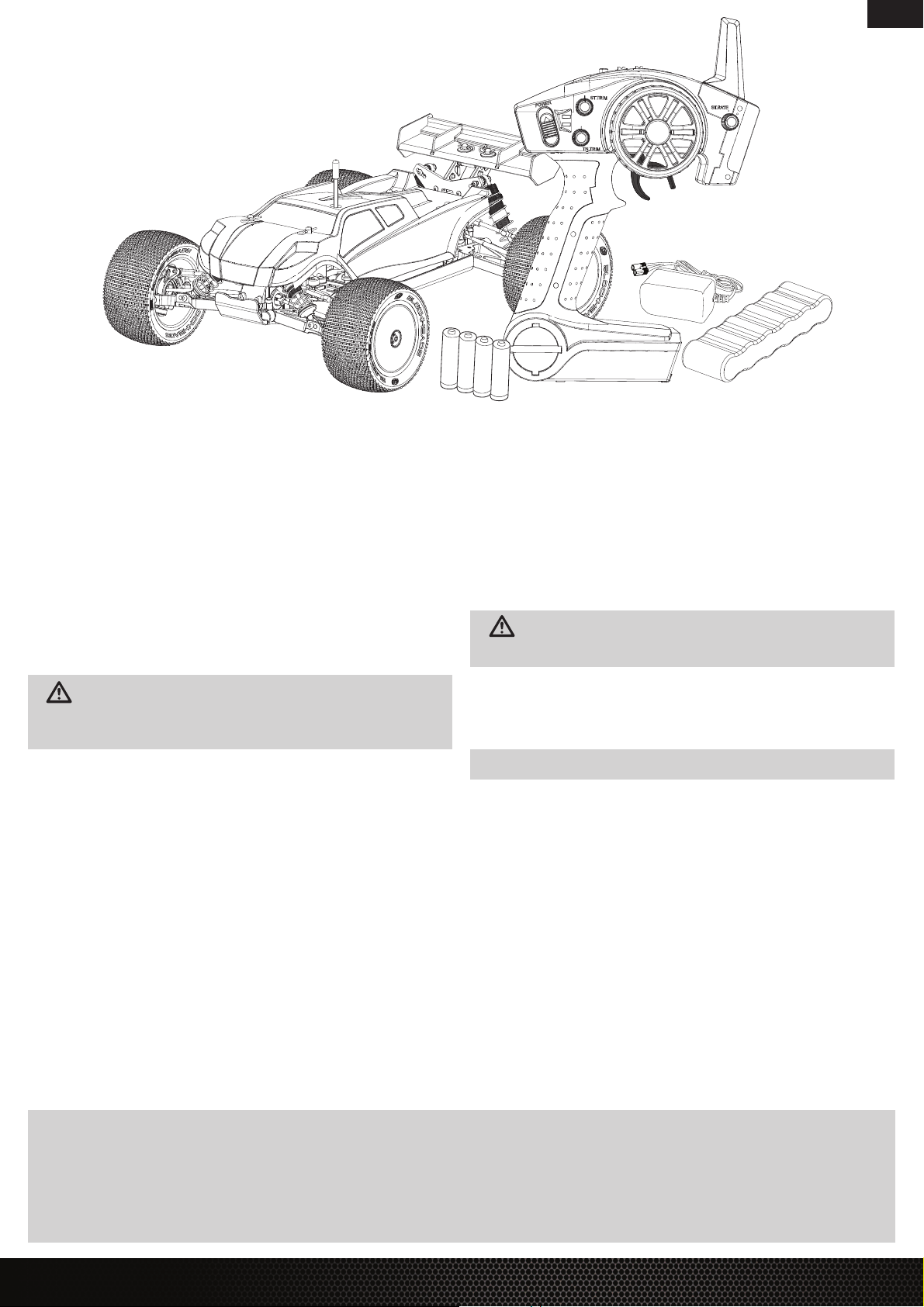
COMPONENTS
• 1/14-Scale Mini 8IGHT-T™ RTR vehicle
• Spektrum™ DX2E 2.4GHz DSMR™ Radio System
• SRS4201 4-Channel DSMR Receiver with Active Vehicle Control™ (AVC®) technology
• Dynamite® Tazer™ Mini Brushless Waterproof ESC
• Dynamite Fuze™ Mini Brushless Motor, 4500Kv
• Spektrum S500 Sport Servo
• Dynamite 7.2V 1200mAh Ni-MH Battery Long with EC3™ Connector
• Losi® AC Wall Charger with EC3 Connector (110V)
• 4 AA batteries (for transmitter)
RECOMMENDED ACCESSORIES
• Soft bristle brush for cleaning
• #0 or #1 Phillips screwdriver
• 2.0mm Hex L wrench
• Thread Lock
TOOLS INCLUDED
• Turnbuckle Wrench
• 4-Way Wrench
• 1.5mm Hex "L" Wrench
• Slipper Adjustment Tool
Use only Dynamite tools or other high-quality tools. Use of inexpensive tools can cause
damage to the small screws and parts used on this type of model.
2
LOSI MINI 8IGHT-T RTR • INSTRUCTION MANUAL
Page 3
CONTENTS
WATER-RESISTANT VEHICLE WITH WATERPROOF ELECTRONICS
Your new Horizon Hobby vehicle has been designed and built with a combination of
waterproof and water-resistant components to allow you to operate the product in many
“wet conditions”, including puddles, creeks, wet grass, snow and even rain.
While the entire vehicle is highly water-resistant, it is not completely waterproof and your
vehicle should NOT be treated like a submarine. The various electronic components used in the
vehicle, such as the Electronic Speed Control (ESC), servo(s) and receiver are waterproof, however, most of the mechanical components are water-resistant and should not be submerged.
Metal parts, including the bearings, hinge pins, screws and nuts, as well as the contacts
in the electrical cables, will be susceptible to corrosion if additional maintenance is not
performed after running in wet conditions. To maximize the long-term performance of your
vehicle and to keep the warranty intact, the procedures described in the “Wet Conditions
Maintenance” section below must be performed regularly if you choose to run in wet
conditions. If you are not willing to perform the additional care and maintenance
required, then you should not operate the vehicle in those conditions.
CAUTION: Failure to exercise caution while using this product and
complying with the following precautions could result in product malfunction
and/or void the warranty.
• Driving in wet conditions can reduce the life of the motor. The additional resistance of
operating in water causes excess strain. Alter the gear ratio by using a smaller pinion or
larger spur gear. This will increase torque (and motor life) when running in mud, deeper
puddles, or any wet conditions that will increase the load on the motor for an extended
period of time.
WET CONDITIONS MAINTENANCE
• Drain any water that has collected in the tires by spinning them at high speed. With the
body removed, place the vehicle upside down and pull full throttle for a few short bursts
until the water has been removed.
CAUTION: Always keep hands, fi ngers, tools and any loose or hanging objects
away from rotating parts when performing the above drying technique.
• Remove the battery pack(s) and dry the contacts. If you have an air compressor or a can
of compressed air, blow out any water that may be inside the recessed connector housing.
• Remove the tires/wheels from the vehicle and gently rinse the mud and dirt off with a
garden hose. Avoid rinsing the bearings and transmission.
EN
GENERAL PRECAUTIONS
• Read through the wet conditions maintenance procedures and make sure that you
have all the tools you will need to properly maintain your vehicle.
• Not all batteries can be used in wet conditions. Consult the battery manufacturer before
use. Caution should be taken when using Li-Po batteries in wet conditions.
• Most transmitters are not water-resistant. Consult your transmitter’s manual or the
manufacturer before operation.
• Never operate your transmitter or vehicle where lightning may be present.
• Do not operate your vehicle where it could come in contact with salt water (ocean
water or water on salt-covered roads), contaminated or polluted water. Salt water
is very conductive and highly corrosive, so use caution.
• Even minimal water contact can reduce the life of your motor if it has not been certifi ed
as water-resistant or waterproof. If the motor becomes excessively wet, apply very light
throttle until the water is mostly removed from the motor. Running a wet motor at high
speeds may rapidly damage the motor.
NOTICE: Never use a pressure washer to clean your vehicle.
• Use an air compressor or a can of compressed air to dry the vehicle and help remove
any water that may have gotten into small crevices or corners.
• Spray the bearings, drive train, fasteners and other metal parts with a water-displacing
light oil. Do not spray the motor.
• Let the vehicle air dry before you store it. Water (and oil) may continue
to drip for a few hours.
• Increase the frequency of disassembly, inspection and lubrication of the following:
- Front and rear axle hub assembly bearings.
- All transmission cases, gears and differentials.
- Motor—clean with an aerosol motor cleaner and re-oil the bushings
with lightweight motor oil.
QUICK START
Please read the entire manual to gain a full understanding of the Mini 8IGHT-T RTR vehicle, fi ne-tuning the setup and performing maintenance.
1. Read the safety precautions found in this manual.
2. Charge the battery. Refer to the included charging warnings
and instructions for battery charging information.
3. Install the AA batteries in the transmitter. Only use alkaline
or rechargeable batteries.
4. Install a fully charged battery in the vehicle.
5. Power ON the transmitter and then the vehicle. Always power the transmitter
ON before the vehicle and power it OFF after the vehicle has been powered OFF.
6. Check the steering and throttle control directions. Verify that the servos
are moving in the correct direction.
7. Drive your vehicle.
8. Perform any necessary maintenance.
LOSI MINI 8IGHT-T RTR • INSTRUCTION MANUAL
3
Page 4
EN
CHARGING WARNINGS
WARNING: Failure to exercise caution while using this product and comply with
the following warnings could result in product malfunction, electrical issues, excessive
heat, FIRE, and ultimately injury and property damage.
• Never leave the battery and charger unattended during use.
• Never charge batteries overnight.
• Read all safety precautions and literature prior to use of this product.
• Never allow children under 14 years of age to charge battery packs.
• Never attempt to charge dead or damaged batteries.
• Never charge a battery if the cable has been pinched or shorted.
• Never allow batteries or charger to come into contact with moisture at any time.
• Never charge batteries in extremely hot or cold places (recommended between 50–80°F
(10–26°C)) or place in direct sunlight.
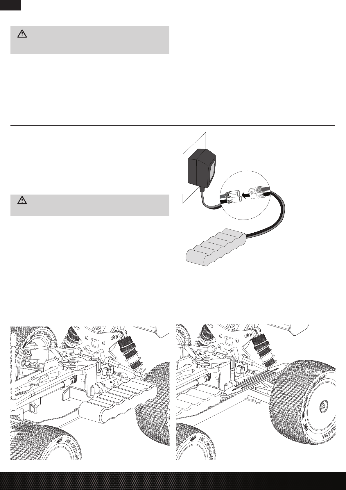
CHARGING THE BATTERY
Charge only batteries that are cool to the touch and are not damaged. Inspect the battery
to make sure it is not damaged e.g., swollen, bent, broken or punctured.
1. Connect the charger to an AC power source, noting proper polarity.
2. Connect the battery connector to the charger connector.
3. Let the battery charge for 3 hours.
4. Disconnect the battery from the charger.
5. Disconnect the charger from the AC power source.
• Always use only Ni-MH rechargeable batteries. This charger cannot charge batteries
such as “heavy duty”, “alkaline”, “mercury” or “lithium” battery.
• Always connect to the charger correctly.
• Always disconnect the battery and charger after charging and let them cool
between charges.
• Always inspect the battery before charging.
• Always terminate all processes and contact Horizon Hobby if the product malfunctions.
• Always make sure you know the specifi cations of the battery to be charged or discharged
to ensure it meets the requirements of this charger.
• Always constantly monitor the temperature of the battery pack while charging.
• Always end the charging process if the charger or battery becomes hot to the touch
or starts to change form during the charge process.
• Always charge in a well ventilated area.
CAUTION: If at any time during the charging process the battery becomes hot
to the touch, disconnect the battery immediately and discontinue the charging process.
INSTALLING THE BATTERY AND POWERING ON THE VEHICLE
1. Remove the body clips and remove the body.
2. Remove the body clips from the battery strap posts and remove the battery strap.
3. Install the fully charged battery in vehicle.
4. Ensure the ESC is powered off.
5. Connect the battery to the ESC.
6. Reinstall the battery strap and body clips.
7. Center the ST TRIM and TH TRIM on the transmitter. Power on the transmitter.
8. Power on the ESC. The vehicle and receiver MUST remain motionless for at least
2 seconds.
9. Reinstall the body and body clips on the vehicle.
4
LOSI MINI 8IGHT-T RTR • INSTRUCTION MANUAL
Page 5
SPEKTRUM DX2E RADIO SYSTEM
EN
4
7
9 10 11
6
5
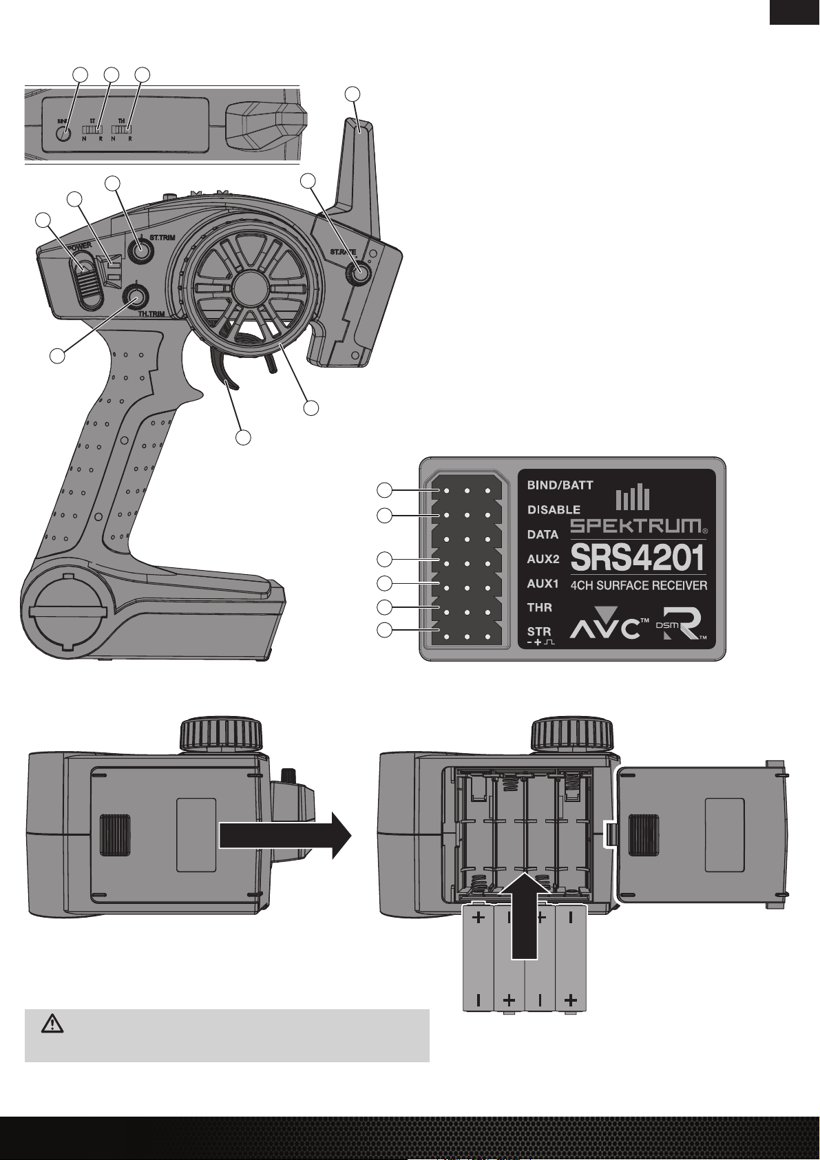
1. Steering Wheel Controls direction (left/right) of the model
3
8
2. Throttle Trigger Controls speed and direction (forward/brake/reverse) of the model
3. Antenna Transmits the signal to the model
4. ON/OFF Switch Turns the power ON/OFF for the transmitter
5. Indicator Lights
- Solid green light—indicates adequate battery power
- Flashing green light—indicates the battery voltage is critically low. Replace batteries
6. ST Trim Adjusts the total steering travel
7. TH Trim Adjusts the total throttle travel
8. ST Rate Adjusts the sensitivity of AVC
9. BIND Button Puts the transmitter into Bind Mode
10. ST. REV Reverses the function of the steering when the wheel is turned left or right
11. TH. REV Reverses the function of the speed control when pulled back or pushed forward
SRS4201 AVC TECHNOLOGY RECEIVER
12. BIND
13. DISABLE
14. AUX 2
15. AUX 1
16. THR
1
2
17. STR
INSTALLING THE TRANSMITTER BATTERIES
12
13
14
15
16
17
1. Push in the battery cover a small amount to release the retaining tab, then remove the cover.
2. Install 4 AA batteries, taking care to align the battery polarity to the diagram in the transmitter’s
battery case.
3. Carefully reinstall the battery cover by aligning the tabs with the slots on the transmitter.
CAUTION: Do not remove the transmitter batteries while the model is powered
on or while operating, as a loss of model control, damage or injury can result.
For more information on the transmitter, go to www.horizonhobby.com and click
on the support tab for the Spektrum DX2E to download the instruction manual.
LOSI MINI 8IGHT-T RTR • INSTRUCTION MANUAL
5
Page 6
EN
SRS4201 STABILITY ASSIST RECEIVER
AVC – ACTIVE VEHICLE CONTROL
The Spektrum SRS4201 receiver features Active Vehicle Control™ (AVC®) technology that
responds similar to traction control in full-scale vehicles. In addition to traction control, AVC
technology also increases steering stability during high-speed driving or while driving over
rough terrain. As you increase the AVC sensitivity, the system increases steering stability and
traction control, similar to reducing the amount of steering rate in a computer transmitter.
Reducing the sensitivity value increases the amount of steering control from the transmitter.
The SRS4201 receiver also enables you to quickly turn AVC on or off if you participate
in organized racing.
IMPORTANT: You must use digital servos with the SRS4201 receiver. Using analog servos
will reduce the performance of the system and may cause analog servos to overheat.
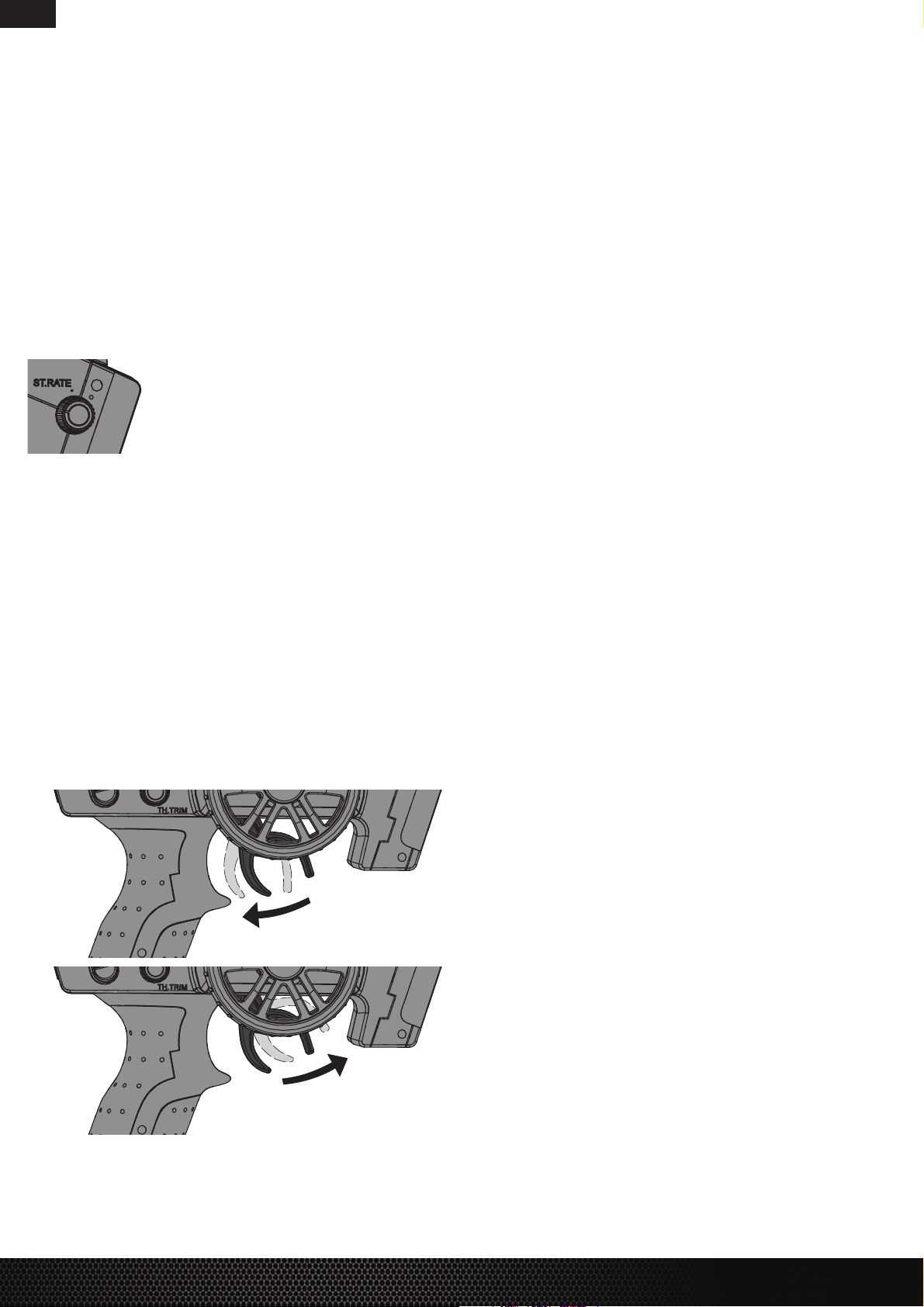
AVC SENSITIVITY
The ST RATE dial adjusts the sensitivity, or stability, value in the receiver. If you increase the
sensitivity, the AVC system becomes more sensitive to the vehicle drifting left or right. You
would use maximum sensitivity during high-speed driving or drag racing, when you want
the vehicle to stay in a straight line. As the sensitivity value increases, the amount of
steering travel decreases.
Turn the ST RATE knob counter-clockwise to reduce the sensitivity.
Turn the ST RATE knob clockwise to increase the sensitivity.
IMPORTANT: The ST RATE knob will only adjust the sensitivity
when the transmitter is bound to a DSMR™ receiver. When
the transmitter is bound to a DSM®, DSM2® or DSM Marine
receiver, the ST RATE knob controls the steering dual rate.
BINDING AND CALIBRATING THE RECEIVER
Your Spektrum DX2E comes prebound to the vehicle; however, if you need to rebind
or calibrate the receiver, follow the instructions below.
1. Insert the Bind Plug in the BIND port on the receiver.
2. Connect a fully charged battery pack to the ESC.
3. Power on the ESC. The orange LED fl ashes, indicating the receiver is in bind mode.
4. Center the ST TRIM and TH TRIM dials on the transmitter.
5. Press and hold the BIND button while powering on the transmitter.
6. Release the BIND button when the orange LED slowly fl ashes. The transmitter and receiver
are linked when the orange LED is solid.
7. Pull the transmitter trigger to Full Throttle.
8. Push the transmitter trigger to Full Brake, then return the trigger to center.
9. Turn the transmitter steering wheel to Full Right.
10. Turn the transmitter steering wheel to Full Left, then return the steering wheel to center.
The orange LED fl ashes once.
11. Remove the Bind Plug, then power off the receiver to save the settings.
12. Power off the transmitter.
CONTROL TEST
Perform a control test with the vehicle wheels off the ground. If the wheels rotate after the
vehicle is powered ON, adjust the TH Trim knob until they stop. To make the wheels move
forward, pull the trigger. To reverse them, wait for the wheels to stop, then push the trigger.
When moving forward, the wheels should maintain a straight line without any steering wheel
input. If not, adjust the ST Trim knob, so the wheels maintain a straight line without having to
turn the steering wheel.
BEFORE RUNNING YOUR VEHICLE
1. Break in the differentials. While holding the chassis with only the left side tires fi rmly on
the ground, give the car about 1/8 throttle for 30 seconds. The right side tires should spin
freely during this time. Repeat this with only the right side tires fi rmly on the ground,
allowing the left side tires to spin freely. Repeat this 2–3 times.
2. Check for free suspension movement. All suspension arms and steering components
should move freely. Any binds will cause the car to handle poorly.
3. Charge the battery.
4. Check the calibration of the ESC. If recalibration is required, refer to the Tazer Mini
Brushless ESC section.
5. Adjust the transmitter settings to your desired confi guration.
DRIVING PRECAUTIONS
• Maintain sight of the vehicle at all times.
• Inspect the vehicle for loose wheel hardware.
• Inspect the steering assembly for any loose hardware. Driving the vehicle off-road
can cause fasteners to loosen over time.
• Do not drive the vehicle in tall grass. Doing so can damage the vehicle or electronics.
• Stop driving the vehicle when you notice a lack of power. Driving the vehicle when
the battery is discharged can cause the receiver to power off. You may lose control
of the vehicle.
• Do not apply the throttle in forward or reverse if the vehicle is stuck. Applying throttle
in this instance can damage the motor or ESC.
• After driving the vehicle, allow the electronics to cool to ambient temperature before
using the next battery pack.
RUN TIME
The largest factor in run time is the capacity of the battery pack. A larger mAh rating
increases the amount of run time experienced.
The condition of a battery pack is also an important factor in both run time and speed.
The battery connectors may become hot during driving. Batteries will lose performance
and capacity over time.
Driving the vehicle from a stop to full speed repeatedly will damage the batteries
and electronics over time. Sudden acceleration will also lead to shorter run times.
TO IMPROVE RUN TIMES
• Keep your vehicle clean and well maintained.
• Allow more airfl ow to the ESC and motor.
• Change the gearing to a lower ratio. A lower ratio lowers the operating temperature of
the electronics. Use a smaller pinion gear or larger spur gear to lower the gear ratio.
• Use a battery pack with a higher mAh rating.
FORWARD
BRAKE/REVERSE
6
LOSI MINI 8IGHT-T RTR • INSTRUCTION MANUAL
Page 7

TAZER MINI BRUSHLESS WATERPROOF ESC (DYNS1425)
EN
ESC PROGRAMMING PROCEDURE
1. Power ON the transmitter and set the transmitter’s throttle endpoint travel to maximum
and the throttle trim to the center position.
2. Leave the throttle trigger at center,then power ON the ESC.
3. Press and hold the Battery Chemistry Button on the power switch for 3 seconds. The LED
fl ashes the current battery chemistry (red = Ni-MH, green = Li-Po).
4. Continue holding the Battery Chemistry Button for another 6 seconds. The ESC changes
battery chemistry and the LED fl ashes the new battery chemistry.
5. Power OFF the ESC. The ESC saves the setting until it is changed.
TRANSMITTER/ESC ENDPOINT CALIBRATION
After executing the setting task, the green LED will fl ash as you release the throttle
trigger to neutral. Once neutral is reached, a beep will sound and the green LED
will glow solid for 1 second. The red LED will begin to fl ash.
a. Move the throttle trigger to full throttle and hold it until a beep sounds and
the red LED glows solid for 1 second. Release the throttle trigger to neutral
and the red LED will glow solid while the green LED will begin to fl ash.
b. Move the throttle trigger to full brake/reverse and hold until a beep sounds
and the green LED glows solid.
c. Release the throttle trigger to neutral. Both red and green LEDs will fl ash
3 times with 3 beeps.
d. Power OFF the ESC and then power ON the ESC to return to normal operation.
OPERATION LED STATUS
(Waiting for Throttle Position)
Neutral Flashing Green Solid Green (1 second)
Forward Flashing Red Solid Red (1 second)
Full Brake/Reverse Solid Red
Flashing Green
LED STATUS
(Position Set)
Solid Green (1 second)
Followed by Red and Green
Flashing 3x
CHANGE ESC RUNNING MODE
Forward/Reverse with Smart Brake, or Forward Only with Brake
The green LED will indicate the currently selected ESC running mode for 4 seconds:
- Green LED Solid: Forward/Reverse (Smart Brake)
- Green LED Flashing: Forward Only (Brake)
a. Move the throttle trigger to full throttle within the 4 seconds to select the
next ESC mode. A beep will sound and the green LED will indicate the new
ESC running mode.
b. To change back to the previous mode, repeat the step above within 4 seconds
of the beep.
c. Both red and green LEDs will fl ash 3 times with 3 beeps.
d. Power OFF the ESC and then power ON the ESC to return to normal operation.
At any time that the ESC is powered and the transmitter is at neutral,
the green LED will indicate the current ESC running mode:
- Green LED Solid: Forward/Reverse (Smart Brake)
- Green LED Flashing: Forward Only (Brake)
FUZE MINI BRUSHLESS MOTOR, 4500KV
PINION SPUR BATTERY GEARING COMMENTS
14T 62T Ni-MH OK This is the stock gearing. If you use a 2S–3S Li-Po, you will need to gear down,
12T (LOSB1862) 62T 2S Li-Po OK This gearing is optimal for a 2S Li-Po.
10T (LOSB1861) 62T 3S Li-Po OK This gearing is optimal for a 3S Li-Po.
CHANGING THE PINION/GEAR RATIO
Your vehicle comes with the 14T pinion gear installed for the
included 6C Ni-MH battery. If you want to use a 2S–3S Li-Po
battery, refer to the Gearing Chart for the proper gearing.
1. Remove the 6 screws securing the gear cover and remove
the gear cover.
2. Loosen the motor screws and slide the motor back.
3. Loosen the setscrew and remove the installed pinion gear.
4. Place the new pinion on the end of the motor shaft so the
setscrew is located over the fl at on the shaft.
5. Position it so the teeth line up with the spur gear and secure
by tightening the setscrew.
6. Tighten the motor screws and reinstall the gear cover.
SETTING THE GEAR MESH
The gear mesh has already been set at the factory. Setting it
is only necessary when changing motors or gears. Proper gear
mesh (how gear teeth meet) is important to the performance
of the vehicle. When the gear mesh is too loose, the spur gear
could be damaged by the pinion gear of the motor. If the mesh
is too tight, speed could be limited and the motor and ESC
will overheat.
1. Remove the 6 screws securing the gear cover and
remove the gear cover.
2. Loosen the motor screws and slide the motor back.
3. Put a small piece of paper between the pinion and
spur gears.
4. Push the gears together while tightening the motor screws.
5. Remove the paper. Check the mesh at 3–5 different
locations around the spur gear for a small amount
of movement.
6. Reinstall the gear cover.
or you will overheat the motor.
LOSI MINI 8IGHT-T RTR • INSTRUCTION MANUAL
7
Page 8

EN
TUNING, ADJUSTING &
MAINTAINING YOUR VEHICLE
• Examine your vehicle on a regular basis.
• Use a brush to remove dirt and dust.
• Look for damage to the suspension arms and other molded parts.
• Re-glue the tires to the wheels, if necessary.
• Use suitable tools to tighten fasteners.
• Make sure the camber and steering linkages are not bent. Replace any bent linkages.
• Adjust the Toe and Camber settings, if necessary.
• Remove the shocks and inspect them for damage. Rebuild the shocks if oil is leaking.
• Inspect electronics and batteries for exposed wires. Repair exposed wires with shrinkwrap or replace the wire.
• Make sure the ESC and receiver are secure on the chassis. Replace the double-sided tape,
if necessary.
• Power on the transmitter. If the green LED is dim or off, replace the AA batteries
in your transmitter.
• Check the spur gear for wear.
CHANGING THE TRAVEL ADJUST SETTINGS
1. Hold the trigger in the full brake position and steering wheel in the full right position while powering on the transmitter. The LED fl ashes rapidly, indicating the programming mode is active.
2. Throttle End Point: Continue holding full throttle. Turn the TH TRIM knob to adjust
the full throttle end point.
3. Brake End Point: Hold the trigger in the full brake position. Turn the TH TRIM knob
to adjust the full brake end point. Return the trigger to the center position.
4. Left Steering End Point: Hold the steering wheel in the full left position. Turn
the ST TRIM knob to adjust the left end point.
5. Right Steering End Point: Hold the steering wheel in the full right position. Turn the ST
TRIM knob to adjust the right end point. Return the steering wheel to the center position.
6. Power off the transmitter to save the travel adjust settings.
The minimum travel is 75%, and the maximum travel is 150%.
IMPORTANT: If the travel is changed on the DX2E, you must rebind and calibrate the SRS4201.
SERVICE/REPAIR
RADIO/SPEED CONTROL & MOTOR
If any problems other than those covered in the troubleshooting section arise, please
call the appropriate electronics service department. They will be able to give the problem
additional specifi c attention and provide instructions for the solution.
MAINTENANCE
If any questions other than those covered in the troubleshooting or maintenance sections
arise, please call the appropriate Horizon product support department.
CLEANING
Performance can be hindered if dirt gets in any of the moving suspension parts. Use
compressed air, a soft paintbrush, or a toothbrush to remove dust or dirt. Avoid using
solvents or chemicals as they can actually wash dirt into the bearings or moving parts,
as well as cause damage to the electronics.
DISABLING THE STABILITY ASSIST FUNCTION
If you participate in organized racing, you may be required to turn Stability Assist off.
To turn Stability Assist off:
1. Insert a Bind Plug in the BIND port on the receiver.
2. Insert a second Bing Plug in the DISABLE port on the receiver.
3. Connect a fully charged battery pack to the ESC.
4. Power on the ESC. The orange LED fl ashes, indicating the receiver is in bind mode.
5. Center the ST TRIM and TH TRIM dials on the transmitter.
6. Press and hold the BIND button while powering on the transmitter.
7. Release the BIND button when the orange LED slowly fl ashes. The transmitter and receiver
are linked when the orange LED is solid.
8. Pull the transmitter trigger to Full Throttle.
9. Push the transmitter trigger to Full Brake, then return the trigger to center.
10. Turn the transmitter steering wheel to Full Right.
11. Turn the transmitter steering wheel to Full Left, then return the steering wheel to center.
The orange LED fl ashes once.
12. Remove the Bind Plugs, then power off the receiver to save the settings.
13. Power off the transmitter.
IMPORTANT: You must calibrate the receiver each time it is placed in bind mode.
To activate AVC, see the steps in "Calibrating the Receiver".
TROUBLESHOOTING GUIDE
PROBLEM POSSIBLE CAUSE SOLUTION
Vehicle does not operate Battery not charged or plugged in Charge battery/plug in
ESC switch not “On” Turn on ESC switch
Transmitter not “On” or low battery Turn on/replace batteries
Motor runs but rear wheels
do not rotate
Steering does not work Servo plug not in receiver properly Make sure the steering servo plug is connected to the receiver steering channel, noting proper polarity
Will not turn one direction Servo gears damaged Replace or repair servo
Motor does not run Motor wire solder joint is damaged Resolder the motor wire with the proper equipment
ESC gets hot Motor over-geared Use smaller pinion or larger spur gear
Poor run time and/or sluggish
acceleration
Poor range and/or glitching Transmitter batteries low Check and replace
Pinion not meshing with spur gear Adjust pinion/spur mesh
Pinion spinning on motor shaft Tighten pinion gear setscrew on motor shaft fl at spot
Transmission gears stripped Replace transmission gears
Drive pin broken Check and replace drive pin
Servo gears or motor damaged Replace or repair servo
Motor wire broken Repair or replace as needed
ESC damaged Contact Horizon Hobby Product Support
Driveline bound up Check wheels and transmission for binding
Battery pack not fully charged Recharge battery
Charger not allowing full charge Try another charger
Driveline bound up Check wheels, transmission for binding
Vehicle battery low Recharge battery
Loose plugs or wires Check all wire connections and plugs
8
LOSI MINI 8IGHT-T RTR • INSTRUCTION MANUAL
Page 9

PROBLEM POSSIBLE CAUSE SOLUTION
The front wheels oscillate The steering gain is set too high Turn down the steering gain
The front wheels turn the wrong
way when the car slides/rotates
The throttle does not reduce when
the car slides/rotates
The steering channel was reversed after
calibration
The steering channel was reversed after
calibration
Rebind and calibrate
Rebind and calibrate
LIMITED WARRANTY
What this Warranty Covers
Horizon Hobby, LLC (“Horizon”) warrants to the original purchaser that the product
purchased (the “Product”) will be free from defects in materials and workmanship
at the date of purchase.
What is Not Covered
This warranty is not transferable and does not cover (i) cosmetic damage, (ii) damage due
to acts of God, accident, misuse, abuse, negligence, commercial use, or due to improper use,
installation, operation or maintenance, (iii) modifi cation of or to any part of the Product, (iv)
attempted service by anyone other than a Horizon Hobby authorized service center, (v)
Product not purchased from an authorized Horizon dealer, or (vi) Product not compliant
with applicable technical regulations.
OTHER THAN THE EXPRESS WARRANTY ABOVE, HORIZON MAKES NO OTHER WARRANTY
OR REPRESENTATION, AND HEREBY DISCLAIMS ANY AND ALL IMPLIED WARRANTIES,
INCLUDING, WITHOUT LIMITATION, THE IMPLIED WARRANTIES OF NON-INFRINGEMENT,
MERCHANTABILITY AND FITNESS FOR A PARTICULAR PURPOSE. THE PURCHASER ACKNOWLEDGES THAT THEY ALONE HAVE DETERMINED THAT THE PRODUCT WILL SUITABLY
MEET THE REQUIREMENTS OF THE PURCHASER’S INTENDED USE.
Purchaser’s Remedy
Horizon’s sole obligation and purchaser’s sole and exclusive remedy shall be that Horizon
will, at its option, either (i) service, or (ii) replace, any Product determined by Horizon to be
defective. Horizon reserves the right to inspect any and all Product(s) involved in a warranty
claim. Service or replacement decisions are at the sole discretion of Horizon. Proof of purchase
is required for all warranty claims. SERVICE OR REPLACEMENT AS PROVIDED UNDER THIS
WARRANTY IS THE PURCHASER’S SOLE AND EXCLUSIVE REMEDY.
Limitation of Liability
HORIZON SHALL NOT BE LIABLE FOR SPECIAL, INDIRECT, INCIDENTAL OR CONSEQUENTIAL DAMAGES, LOSS OF PROFITS OR PRODUCTION OR COMMERCIAL LOSS IN ANY WAY,
REGARDLESS OF WHETHER SUCH CLAIM IS BASED IN CONTRACT, WARRANTY, TORT,
NEGLIGENCE, STRICT LIABILITY OR ANY OTHER THEORY OF LIABILITY, EVEN IF HORIZON HAS
BEEN ADVISED OF THE POSSIBILITY OF SUCH DAMAGES. Further, in no event shall the liability
of Horizon exceed the individual price of the Product on which liability is asserted. As Horizon
has no control over use, setup, fi nal assembly, modifi cation or misuse, no liability shall be
assumed nor accepted for any resulting damage or injury. By the act of use, setup or assembly,
the user accepts all resulting liability. If you as the purchaser or user are not prepared to
accept the liability associated with the use of the Product, purchaser is advised to return
the Product immediately in new and unused condition to the place of purchase.
Law
These terms are governed by Illinois law (without regard to confl ict of law principals). This
warranty gives you specifi c legal rights, and you may also have other rights which vary from
state to state. Horizon reserves the right to change or modify this warranty at any time
without notice.
WARRANTY SERVICES
Questions, Assistance, and Services
Your local hobby store and/or place of purchase cannot provide warranty support or service.
Once assembly, setup or use of the Product has been started, you must contact your local
distributor or Horizon directly. This will enable Horizon to better answer your questions and
service you in the event that you may need any assistance. For questions or assistance, please
visit our website at www.horizonhobby.com, submit a Product Support Inquiry, or call the toll
free telephone number referenced in the Warranty and Service Contact Information section
to speak with a Product Support representative.
Inspection or Services
If this Product needs to be inspected or serviced and is compliant in the country you live and
use the Product in, please use the Horizon Online Service Request submission process found
on our website or call Horizon to obtain a Return Merchandise Authorization (RMA) number.
Pack the Product securely using a shipping carton. Please note that original boxes may be included, but are not designed to withstand the rigors of shipping without additional protection.
Ship via a carrier that provides tracking and insurance for lost or damaged parcels, as Horizon
is not responsible for merchandise until it arrives and is accepted at our facility. An Online
Service Request is available at http://www.horizonhobby.com/content/_service-center_renderservice-center. If you do not have internet access, please contact Horizon Product Support
to obtain a RMA number along with instructions for submitting your product for service.
When calling Horizon, you will be asked to provide your complete name, street address, email
address and phone number where you can be reached during business hours. When sending
product into Horizon, please include your RMA number, a list of the included items, and a
brief summary of the problem. A copy of your original sales receipt must be included for warranty consideration. Be sure your name, address, and RMA number are clearly written on the
outside of the shipping carton.
NOTICE: Do not ship Li-Po batteries to Horizon. If you have any issue
with a Li-Po battery, please contact the appropriate Horizon Product
Support offi ce.
Warranty Requirements
For Warranty consideration, you must include your original sales receipt verifying
the proof-of-purchase date. Provided warranty conditions have been met, your Product
will be serviced or replaced free of charge. Service or replacement decisions are at the sole
discretion of Horizon.
Non-Warranty Service
Should your service not be covered by warranty, service will be completed and
payment will be required without notifi cation or estimate of the expense unless
the expense exceeds 50% of the retail purchase cost.
By submitting the item for service you are agreeing to payment of the service without notifi cation. Service estimates are available upon request. You must include this request with your
item submitted for service. Non-warranty service estimates will be billed a minimum of ½ hour
of labor. In addition you will be billed for return freight. Horizon accepts money orders and cashier’s checks, as well as Visa, MasterCard, American Express, and Discover cards. By submitting any item to Horizon for service, you are agreeing to Horizon’s Terms and Conditions found
on our website http://www.horizonhobby.com/content/_service-center_render-service-center.
ATTENTION: Horizon service is limited to Product compliant in the country of use
and ownership. If received, a non-compliant Product will not be serviced. Further,
the sender will be responsible for arranging return shipment of the un-serviced
Product, through a carrier of the sender’s choice and at the sender’s expense.
Horizon will hold non-compliant Product for a period of 60 days from notifi cation, after which it will be discarded.
EN
LOSI MINI 8IGHT-T RTR • INSTRUCTION MANUAL
9
Page 10

EN
WARRANTY AND SERVICE CONTACT INFORMATION
COUNTRY OF PURCHASE HORIZON HOBBY CONTACT INFORMATION ADDRESS
United States of America Horizon Service Center
(Repairs and Repair Requests)
Horizon Product Support
(Product Technical Assistance)
Sales
United Kingdom Service/Parts/Sales:
Horizon Hobby Limited
Germany Horizon Technischer Service service@horizonhobby.de
Sales: Horizon Hobby GmbH
France Service/Parts/Sales:
Horizon Hobby SAS
China Service/Parts/Sales:
Horizon Hobby - China
servicecenter.horizonhobby.com/RequestForm/
www.quickbase.com/db/bghj7ey8c?a=GenNewRecord
888-959-2305
sales@horizonhobby.com
888-959-2305
sales@horizonhobby.co.uk
+44 (0) 1279 641 097
+49 (0) 4121 2655 100
infofrance@horizonhobby.com
+33 (0) 1 60 18 34 90
info@horizonhobby.com.cn
+86 (021) 5180 9868
4105 Fieldstone Rd
Champaign, Illinois, 61822 USA
Units 1–4 Ployters Rd
Staple Tye
Harlow, Essex
CM18 7NS, United Kingdom
Christian-Junge-Straße 1
25337 Elmshorn, Germany
11 Rue Georges Charpak
77127 Lieusaint, France
Room 506, No. 97 Changshou Rd.
Shanghai, China 200060
FCC INFORMATION
This device complies with part 15 of the FCC rules. Operation is subject to the following
two conditions: (1) This device may not cause harmful interference, and (2) this device must
accept any interference received, including interference that may cause undesired operation.
CAUTION: Changes or modifi cations not expressly approved by the party responsible for compliance could void the user’s authority to operate the equipment.
This product contains a radio transmitter with wireless technology which has been tested
and found to be compliant with the applicable regulations governing a radio transmitter
in the 2.400 GHz to 2.4835 GHz frequency range.
ANTENNA SEPARATION DISTANCE
When operating your Spektrum transmitter, please be sure to maintain a separation distance
of at least 5 cm between your body (excluding fi ngers, hands, wrists, ankles and feet) and
the antenna to meet RF exposure safety requirements as determined by FCC regulations.
The following illustrations show the approximate 5 cm RF exposure area and typical
hand placement when operating your Spektrum transmitter.
IC INFORMATION
This device complies with Industry Canada licence-exempt RSS standard(s). Operation is
subject to the following two conditions: (1) this device may not cause interference, and (2)
this device must accept any interference, including interference that may cause undesired
operation of the device.
COMPLIANCE INFORMATION FOR THE EUROPEAN UNION
DECLARATION OF CONFORMITY
(in accordance with ISO/IEC 17050-1)
No. HH2014022804U1
Product(s): Mini 8IGHT-T RTR, AVC: 1/14 4WD Truggy (includes Spektrum DX2E
Transmitter with Spektrum SRS4201 Receiver)
Item Number(s): LOS01000I
Equipment class: 1
The object of declaration described above is in conformity with the requirements of the specifi -
cations listed below, following the provisions of the European R&TTE Directive 1999/5/EC,
EMC Directive 2004/108/EC and LVD Directive 2006/95/EC:
EN 300-328 V1.8.1
EN 301 489-1 V1.9.2: 2012
EN 301 489-17 V2.1.1: 2009
INSTRUCTIONS FOR DISPOSAL OF WEEE BY USERS IN THE
EUROPEAN UNION
This product must not be disposed of with other waste. Instead, it is the user’s responsibility to dispose of their waste equipment by handing it over to a designated collections
point for the recycling of waste electrical and electronic equipment. The separate collection
and recycling of your waste equipment at the time of disposal will help to conserve natural
resources and ensure that it is recycled in a manner that protects human health and the
environment. For more information about where you can drop off your waste equipment for
recycling, please contact your local city offi ce, your household waste disposal service or where
you purchased the product.
EN 60950-1:2006+A11:2009+A1:2010+A12: 2011
EN 62311:2008
EN 55022:2010 + AC:2011
EN 55024:2010
EN 61000-3-2:2006+A1:2009+A2:2009
EN 61000-3-3:2008
Signed for and on behalf of:
Horizon Hobby, LLC
Champaign, IL USA
December 19, 2014
Mike Dunne
Executive Vice President
Product Divisions
Horizon Hobby, LLC
10
LOSI MINI 8IGHT-T RTR • INSTRUCTION MANUAL
Page 11

PARTS LISTINGS/TEILELISTE/LISTE DES PIÈCES/ELENCO COMPONENTI
PART # ENGLISH DEUTSCH FRANÇAIS ITALIANO
DYNS1425 Tazer Mini Brushless Waterproof ESC Tazer Mini Brushless wasserdichter Regler Mini contrôleur brushless Tazer étanche ESC brushless impermeabile Tazer Mini
DYN1473 7.2V 1200mAh Ni-MH Battery Long
with EC3™ Connector
DYN4830 Fuze Mini Brushless Motor, 4500Kv Fuze Mini Brushless Motor, 4500Kv Mini moteur brushless Fuze 4500Kv Motore brushless Fuze Mini, 4500Kv
LOS41003 Front/Rear Wheel Set White (4): Mini 8T Losi Mini 8T: Räder v/h weiß (4) Set de jantes av/arr blanches (4) : Mini 8T Set ruote bianche anter/poster (4):
LOS41004 Blockhead Tires Premounted (2): Mini 8T Losi Mini 8T: Blockhead Reifen Pneus Blockheads prémontés (2) :
LOS210000 Body Painted: Mini 8T Losi Mini 8T: Karosserie lackiert Carrosserie peinte : Mini 8T Carrozzeria verniciata: Mini 8T
LOS211000 Front/Rear Shock Tower Set: Mini 8T Losi Mini 8T: Dämpferbrücke Support d'amortisseur av/arr : Mini 8Tc Set torre ammort. anter/poster: Mini 8T
LOS211001 Main Chassis: Mini 8T Chassis: Mini 8T Châssis principal: Mini 8T Telaio principale: Mini 8T
LOS211002 Chassis Guard Set: Mini 8T Chassis Schützer Set: Mini 8T Jeu de protège-châssis: Mini 8T Set protezione telaio: Mini 8T
LOS211003 Upper Deck Support, Body Mounts:
Mini 8T
LOS211004 Steering Hardware Set: Mini 8T Lenkung Hardware Set: Mini 8T Visserie pour direction: Mini 8T Set bulloni sterzo: Mini 8T
LOS212000 Drive Shaft Set: Mini 8T Antriebsachse Set: Mini 8T Jeu d’arbres d’entraînement: Mini 8T Set albero di trasmissione: Mini 8T
LOS212001 Dogbone Set (4): Mini 8T Rally Antriebsknochen Set: Mini 8T Rally Ensemble de système
LOS212002 Axle Set (2): Mini 8T Achsen Set: Mini 8T Jeu de fusées: Mini 8T Asse Set: Mini 8T
LOS212003 Wheel Hex Set : Mini 8T Losi Mini 8T: Radmutterset Set d'hexagones de roues : Mini 8T Set ruote esagonali: Mini 8T
LOS214000 Front/Rear Suspension Arm Set: Mini 8T Querlenkerset vorne / hinten Front:
LOS214001 Turnbuckle Set (6): Mini 8T Gewindestangen Set: Mini 8T Jeu de tendeurs: Mini 8T Set tenditore: Mini 8T
LOS214002 Hinge Pin Set (4): Mini 8T Losi Mini 8T: Hinge Pin Set (4) Axes de suspension (4) : Mini 8T Set perni cerniere (4): Mini 8T
LOS216000 Hardware Set: Mini 8T Hardware Set: Mini 8T Visserie: Mini 8T Set bulloni: Mini 8T
LOS217000 Bearing Set: Mini 8T Losi Mini 8T: Lagerset Set de roulements : Mini 8T Set cuscinetto: Mini 8T
LOSA4002 Antenna Kit Antenne Accessoires d'antenne Kit antenna
LOSB1335 Wing Set: Mini 8IGHT Spoiler Set: Mini 8IGHT Aileron: Mini 8IGHT Set alettoni: Mini 8IGHT
LOSB1863 Pinion Gear 14T: Mini 8IGHT Ritzel, 14Z: Mini 8IGHT Pignon, 14 dents: Mini 8IGHT Ruota conica, 14T: Mini 8IGHT
LOSB1887 Spindle, Hub Carrier Set: Mini 8IGHT Achsschenkel, Radträgerset: Mini 8IGHT Ensemble fusée/moyeu/porte-fusée: Mini
LOSB1888 Suspension Mount Set: Mini 8IGHT Querlenkerhalterset: Mini 8IGHT Ensemble support de suspensions: Mini
LOSB1891 Ball Stud Set: Mini 8IGHT Kugelkopfset: Mini 8IGHT Jeu de rotules: Mini 8IGHT Set perni sferici: Mini 8IGHT
LOSB1896 Ball Cup (12): Mini 8IGHT Kugelpfanne: Mini 8IGHT Coupelle de rotule: Mini 8IGHT Coppella della sfera: Mini 8IGHT
LOSB1898 Suspension Bushing Set: Mini 8IGHT Buchse für Querlenker: Mini 8IGHT Jeu de bagues pour suspension: Mini
LOSB1902 Battery Hold Down Set: Mini 8IGHT Akkuhalter Set: Mini 8IGHT Ensemble de fi xation des accus: Mini
LOSB1905 Motor Mount & Adaptor Set: Mini 8IGHT Motorhalter und Adapter Set: Mini 8IGHT Support moteur et ensemble adaptateur:
LOSB1908 Wing Mount & Brace Set: Mini 8IGHT Spoilerhalter hinten: Mini 8IGHT Ensemble support et entretoise d’aileron:
LOSB1911 Front Shock Body Set: Mini 8IGHT Stoßdämpfergehäuse vorne: Mini 8IGHT Jeu de corps d’amortisseur avant: Mini
LOSB1912 Rear Shock Body Set: Mini 8IGHT Stoßdämpfergehäuse hinten: Mini 8IGHT Jeu de corps d’amortisseur arrière: Mini
LOSB1913 Shock Piston Set: Mini 8IGHT Stoßdämpferkolben Set: Mini 8IGHT Jeu de pistons d’amortisseur: Mini 8IGHT Set pistone ammortizzatore: Mini 8IGHT
LOSB1914 Front Shock Shaft Set: Mini 8IGHT Stoßdämpferkolbenstange Set: Mini
LOSB1915 Rear Shock Shaft Set: Mini 8IGHT Stoßdämpferkolbenstange Set: Mini
LOSB1916 Shock Retainer Set: Ball and Cap Set:
Mini 8IGHT
LOSB1917 Shock Rebuild Set: Mini 8IGHT Reparaturset f. Stoßdämpfer: Mini 8IGHT Nécessaire de réparation d’amortisseur:
LOSB1918 Front Shock Spring Set: Mini 8IGHT Federnsatz vorne: Mini 8IGHT Jeu de ressorts d’amortisseur avant:
LOSB1919 Rear Shock Spring Set: Mini 8IGHT Federnsatz hinten: Mini 8IGHT Jeu de ressorts d’amortisseur arrière:
LOSB1921 Front, Rear Gearbox Set: Mini 8IGHT Getriebegehäuse vorne / hinten: Mini
Dynamite 7.2V 1200mAh NiMH Battery,
Lang m/EC3: Minis
Losi Mini 8T: Chassistr. u. Karosseriehalter Renfort supérieur avec support
Mini 8T
8IGHT
8IGHT
Dämpferkappe mit Kugel Set: Mini 8IGHT Jeu de chapes et rotules d’amortisseur:
8IGHT
Batterie 7.2V 1200mA Ni-MH
avec prise EC3
Mini 8T
de carrosserie : Mini 8T
d'entraînement (Dogbone): Mini 8T
Bras de suspension avant/arrière: Mini 8T Set braccio sospensione anteriore, poste-
8IGHT
8IGHT
8IGHT
8IGHT
Mini 8IGHT
Mini 8IGHT
8IGHT
8IGHT
Jeu de tiges d’amortisseur avant: Mini
8IGHT
Jeu de tiges d’amortisseur arrière: Mini
8IGHT
Mini 8IGHT
Mini 8IGHT
Mini 8IGHT
Mini 8IGHT
Carter de différentiel avant/arrière: Mini
8IGHT
Batteria lunga 7.2V 1200mAh Ni-MH
con connettore EC3
Mini 8T
Gomme Blockhead premontate (2):
Mini 8T
Piattaforma superiore, supporto
carrozzeria: Mini 8T
Rally Set semiassi: Mini 8T
riore: Mini 8T
Albero, mozzo, porta-piastre: Mini 8IGHT
Set montaggio sospensione: Mini 8IGHT
Set boccole sospensione: Mini 8IGHT
Set per tenere la batteria: Mini 8IGHT
Set montante e adattatore del motore:
Mini 8IGHT
Set montante e staffa alettone: Mini
8IGHT
Set corpo ammortizzatore anteriore:
Mini 8IGHT
Set corpo ammortizzatore posteriore:
Mini 8IGHT
Set albero ammortizzatore anteriore:
Mini 8IGHT
Set albero ammortizzatore posteriore:
Mini 8IGHT
Ammortizzatore, set sfera e cappuccio:
Mini 8IGHT
Set ricondizionamento ammortizzatore:
Mini 8IGHT
Set molla ammortizzatore anteriore:
Mini 8IGHT
Set molla ammortizzatore posteriore:
Mini 8IGHT
Set scatola cambio anteriore, posteriore:
Mini 8IGHT
38
38
LOSI TEN-RALLYX RTR • MANUALE DI ISTRUZIONI
LOSI MINI 8IGHT-T RTR
Page 12

PART # ENGLISH DEUTSCH FRANÇAIS ITALIANO
LOSB1922 Spur Gear Set: Mini 8IGHT Zahnräder Set: Mini 8IGHT Couronne: Mini 8IGHT Set ruota dentata cilindrica: Mini 8IGHT
LOSB1923 F/R Diff Gear, Housing & Spacer Set:
Mini 8IGHT
LOSB1924 Slipper Plate Set: Mini 8IGHT Rutschkupplung Scheibe Set: Mini 8IGHT Ensemble de plateaux pour limiteur
LOSB1925 Slipper Pad Set: Mini 8IGHT Rutschkupplung Belag Set: Mini 8IGHT Ensemble patinant: Mini 8IGHT Set pastiglie del pattino: Mini 8IGHT
LOSB1928 Diff Outdrive Set: Mini 8IGHT Diff. Antriebsklauen Set: Mini 8IGHT Jeu d’arbres de sortie de différentiel:
LOSB1929 Center Outdrive Set: Mini 8IGHT Losi Antriebsklaue Set Mitte: Mini 8IGHT Noix de cardan central : Mini 8ight Set trasmissione centrale: Mini 8IGHT
LOSB1930 O-Ring Set: Mini 8IGHT O-Ring Set: Mini 8IGHT Jeu de joints toriques: Mini 8IGHT Set 0-ring: Mini 8IGHT
SPM2322 DX2E DSMR Radio System DX2E DSMR Fernsteuerung Emetteur DX2E DSMR Radiocomando DX2E DSMR
SPMSRS4201 SRS4201 4-Channel DSMR
AVC Receiver, Waterproof
SPMS500 S500 Sport Servo S500 Sport Servo Servo S500 Servo S500 Sport
Differential vorne / hinten m. Gehäuse
Set: Mini 8IGHT
SRS4201 4-Kanal DSMR AVC
Empfänger, Spritzwassergeschützt
Ensemble engrenages, carter et bagues
pour différentiel AV/AR: Mini 8IGHT
de couple: Mini 8IGHT
Mini 8IGHT
Récepteur SRS4201 4 voies
DSMR AVC étanche
Ingranaggi differenziale anteriore/
posteriore, set alloggiamento e
distanziatore: Mini 8IGHT
Set piastra pattino: Mini 8IGHT
Set bicchierino differenziale: Mini 8IGHT
Ricevitore SRS4201 4-canali DSMR AVC,
impermeabile
OPTIONAL PARTS/OPTIONALE BAUTEILE/PIÈCES OPTIONNELLES/PEZZI OPZIONALI
PART # ENGLISH DEUTSCH FRANÇAIS ITALIANO
DYN1476 7.4V 2000mAh 2S 30C Li-Po Dynamite 7,4V 2000mAh 2S 30C Li-Po Batterie 7,4V 2000mA 2S 30C Li-Po Batteria 7,4V 2000mAh 2S 30C Li-Po
LOS210001 Clear Body Set: Mini 8T Losi Mini 8T: Karosserie transp. Carrosserie transparente : Mini 8T Set carrozzeria trasparente: Mini 8T
LOS311000 F/R Shock Tower Battery Brace Carbon
Set: 8T
LOS312000 Front CV Driveshaft: 8T Losi Mini 8T: Antriebswellen Set vorne Cardan avant CVD : Mini 8T Albero trasmissione CV anter.: 8T
LOS312001 Rear CV Driveshaft: 8T Losi Mini 8T: Antriebswellen Set hinten Cardan arrière CVD : Mini 8T Albero trasmissione CV poster.: 8T
LOSB1870 Servo Mount Aluminum Losi Servobefestigung Aluminium: Mini 8 Support de servo en aluminium Supporto servi alluminio
LOSB1877 Rear Hub Set, Aluminum Radträger hinten, Aluminium Jeu de moyeux arrière, aluminium Set mozzo posteriore, alluminio
LOSB1878 Carrier Set, Aluminum Achsschenkelhalter Set, Aluminium Jeu de porte-fusées, aluminium Set porta-piastre, alluminio
LOSB1879 Spindle Set, Aluminum Achsschenkelset Set, Aluminium Jeu de fusées, aluminium Set albero, alluminio
LOSB1885 Front Suspension Mount Set, Aluminum Querlenkerhalterset vorne, Aluminium Ensemble support de suspensions avant,
LOSB1899 Rear Suspension Mount Set, Alum:
Mini 8IGHT
LOSB1920 Lightweight Center Outdrive Set Losi Antriebsklaue mitte Leichtbau:
LOSB1926 Lightweight Diff Outdrive Set Losi Antriebsklaue vorne/hinten
LOSB1938 Front Shock Shaft Set Ti-Ni Losi Kolbenstange vorne Ti-Ni: Mini 8 Tiges d'amortisseurs avant Ti-Ni Set albero ammort. anteriore Ti-Ni
LOSB1939 Rear Shock Shaft Set Ti-Ni Losi Kolbenstange hinten Ti-Ni: Mini 8 Tiges d'amortisseurs arrière Ti-Ni Set albero ammort. posteriore Ti-Ni
LOSB1940 Front Shock Bodies, Hard Anodized Dämpfergehäuse vorne hart elox. Corps d'amortisseurs avant,
LOSB1941 Rear Shock Bodies, Hard Anodized Dämpfergehäuse hinten hart elox. Corps d'amortisseurs arrière,
Carbon Dämpferbrücke / Akkuhalter Support d'amortisseurs et de batterie
en carbone : Mini 8T
aluminium
Querlenkerhalterset hinten, Alu. Ensemble support de suspensions arrière,
aluminium: Mini 8IGHT
Noix de cardan central allégées Set trasmissione centrale leggero
Mini 8
Noix de sorties de différentiel allégées Set trasmissione diff leggero
Leichtbau: Mini 8
anodisés dur
anodisés dur
Set torre ammort. anter/poster
supporto batteria carbon: 8T
Set montante sospensione anteriore,
alluminio
Set supporto sospensione post., Allum.:
Mini 8IGHT
Corpo ammort. anteriore, anodizzato
Corpo ammort. posteriore, anodizzato
LOSI TEN-RALLY X RTR • MANUALE DI ISTRUZIONI
LOSI MINI 8IGHT-T RTR
39
39
Page 13

VUE ÉCLATÉE ARRIÈRE
REAR EXPLODED VIEW
HECK EXPLOSIONSZEICHNUNG
VISTA ESPLOSA DELLA PARTE POSTERIORE
LOS216000
LOS41003
LOS41004
LOS217000
LOS212003
LOS216000
LOSB1335
LOS216000
LOS216000
LOSB1908
LOS216000
LOSB1891
LOS214001
LOS216000
LOSB1888
LOSB1891
LOS212003
LOS212002
LOS212001
LOS214002
LOS214002
LOS216000
LOS214000
LOSB1887
LOS217000
40
40
LOS211000
LOS216000
LOS216000
LOSB1921
LOSB1888
LOSI TEN-RALLYX RTR • MANUALE DI ISTRUZIONI
LOSI MINI 8IGHT-T RTR
Page 14

LOS217000
LOS216000
DIFFERENZIAL V/H
DIFFÉRENTIEL AV/ARR
FRONT/REAR DIFFERENTIAL
DIFFERENZIALE ANTERIORE/POSTERIORE
LOSB1923
LOS216000
LOSB1928
VUE ÉCLATÉE AVANT
FRONT EXPLODED VIEW
FRONT EXPLOSIONSZEICHNUNG
LOS41004
VISTA ESPLOSA DELLA PARTE ANTERIORE
LOSB1887
LOSB1891
LOS217000
LOS212003
LOSB1891
LOS41003
LOS217000
LOS212003
LOS216000
LOSB1898
LOS212002
FRONT / FRONT / AVANT / ANTERIORE
LOS216000
LOSB1928
LOS217000
LOS211003
LOS216000
LOS211000
LOS214001
LOS216000
LOSB1929
LOS217000
LOSB1923
REAR / HECK / ARRIÈRE / POSTERIORE
LOS216000
LOS212000
LOS216000
LOSB1888
LOSB1921
LOS214002
LOSB1887
LOS212001
LOSB1898
LOS214000
LOS216000
LOS216000
LOSI TEN-RALLY X RTR • MANUALE DI ISTRUZIONI
LOSI MINI 8IGHT-T RTR
LOSB1888
LOSB1907
41
41
Page 15

p
LOS216000
LOSB1923
LOS211002
CHASSIS EXPLODED VIEW
VUE ÉCLATÉE DU CHÂSSIS
VISTA ESPLOSA DEL TELAIO
CHASSIS EXPLOSIONSZEICHNUNG
LOS211003
LOS216000
LOS212000
LOS217000
LOSB1922
LOS211003
LOSB1924
LOS217000
LOSB1925
LOS216000
LOSB1924
LOS216000
LOS211003
LOSB1863
LOSB1929
LOSB1905
DYN4830
LOSB1905
LOSB1902
LOS216000
LOS216000
DYN1473
LOSB1902
LOS216000
LOSA4002
LOS216000
LOS212000
LOS211004
DYNS1425
LOSB1903
SPMS500
LOS211003
LOS216000
LOS211004
LOS216000
LOS214001
SPMSRS4201
LOS211001
LOS211004
42
42
42
LOS217000
LOS216000
LOS217000
LOS211004
LOSB1891
LOS214001
LOSI TEN-RALLYX RTR • MANUALE DI ISTRUZIONI
LOSI MINI 8IGHT-T RTR • MANUALE DI ISTRUZIONI
LOS217000
LOSI MINI 8IGHT-T RTR
Page 16

STOSSDÄMPFER V/H
FRONT/REAR SHOCKS
AMORTISSEURS AV/ARR
LOSB1916
LOSB1916
AMMORTIZZATORI ANTERIORE/POSTERIORE
LOSB1918
LOSB1919
LOSB1917
LOSB1917
LOSB1911
LOSB1912
LOSB1916
LOSB1917
LOSB1914
LOSB1911
LOSB1913
LOSB1916
LOSB1917
LOSB1915
LOSB1913
LOSB1912
LOSI MINI 8IGHT-T RTR • MANUALE DI ISTRUZIONI
LOSI TEN-RALLY X RTR • MANUALE DI ISTRUZIONI
LOSI MINI 8IGHT-T RTR
43
43
43
Page 17

Mini 8IGHT-T
0 degree
29.5mm
Stock
3-hole piston/30 wt
Position 2
Position 2/Inside
SETUP SHEET
Inside
Outside
4
3
2
1
1
3
4
2
3 degrees
Electronics
Fuze 4500Kv
TAZER Mini Brushless Waterproof ESC
1200mAh 7.2V Ni-MH
Notes
24.5mm
Stock
3-hole piston/25 wt
Position 2-B
Position 3/Inside
2000mAh 7.4V 2S Li-Po (Gearing: 62T/12T)
62T/14T
Inside
Outside
4
3
2
1
1
3
4
2
44
44
LOSI TEN-RALLYX RTR • MANUALE DI ISTRUZIONI
LOSI MINI 8IGHT-T RTR
Page 18

SETUP SHEET
4
3
2
1
Inside
Outside
Inside
Outside
1
3
4
2
4
3
2
1
1
3
4
2
Electronics
Notes
LOSI TEN-RALLY X RTR • MANUALE DI ISTRUZIONI
LOSI MINI 8IGHT-T RTR
45
45
Page 19

SETUP SHEET
4
3
2
1
Inside
Outside
Inside
Outside
1
3
4
2
4
3
2
1
1
3
4
2
46
46
Electronics
Notes
LOSI TEN-RALLYX RTR • MANUALE DI ISTRUZIONI
LOSI MINI 8IGHT-T RTR
Page 20

WWW.LOSI.COM
46541.1
Created 12/14 LOS01000I
©2015 Horizon Hobby, LLC.
Losi, AVC, Active Vehicle Control, 8IGHT-T, DSM, DSM2, DSMR, Dynamite, Fuze, Tazer, EC3, and the
Horizon Hobby logo are trademarks or registered trademarks of Horizon Hobby, LLC.
The Spektrum trademark is used with permission of Bachmann Industries, Inc. All other trademarks,
service marks and logos are property of their respective owners. Patents pending.
 Loading...