

Page 1
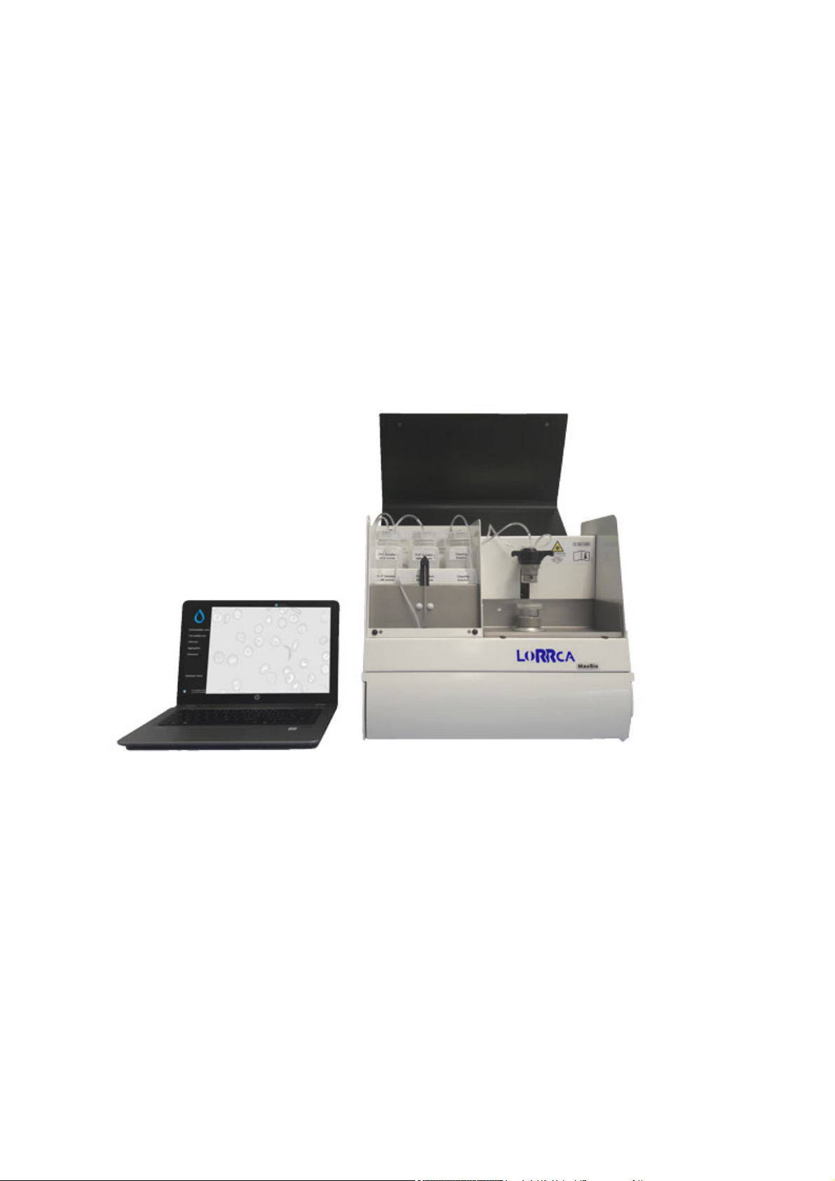
LORRCA MAXSIS
USER MANUAL
Version 5.04 MRN-231-EN
Master Registration Number: MRN-231-EN
Page 2

Page 3

Manufacturer: RR Mechatronics Manufacturing B.V.
Phone: +31 229 291 129
Fax: +31 229 241 534
E-mail: [email protected]
Internet: http://www.rrmechatronics.com
P.O. Box 225
Postal address:
1620 AE Hoorn
The Netherlands
De Corantijn 13
Office address:
1689 AN Zwaag
The Netherlands
© Copyright RR Mechatronics Manufacturing B.V.
All rights reserved.
Subject to changes without prior notice.
Issued by the Support Department of RR Mechatronics
Page 4

Page 5

Document history overview
Published date Friday, 15 March 2019
Issue No Date Revised
Section(s)
MRN-231-EN
Changes Authorised
5.04 March 2019 Safety
Maintenance
5.03 January 2019 Installation
5.02 October 2017 Installation
Installation
Operational
instructions
Program
Operational
instructions
Program
Mains specification
changed
Oxygenscan
procedure changed
Cleaning
instructions
changed
Document History
added as appendix,
only latest changes
in introduction
Introduction of
Oxygenscan option
Introduction
Software version
5.xx
Lorrca 1.01
H. Schavemaker
H. Schavemaker
H. Schavemaker
Lorrca Maxsis User Manual Page 3
Version 5.04 MRN-231-EN
Page 6

Page 7

Contents
CONTENTS
1. ABOUT RR MECHATRONICS .................................................................................... 11
2. INTRODUCTION .......................................................................................................... 12
2.1. About this manual .................................................................................................... 12
2.2. Typographical conventions ...................................................................................... 13
2.3. Used symbols .......................................................................................................... 14
3. INSTRUMENT DESCRIPTION ..................................................................................... 15
3.1. Instrument label Lorrca® MaxSis ............................................................................ 16
3.2. Technical specifications ........................................................................................... 17
3.3. Introduction Lorrca® MaxSis ................................................................................... 20
3.3.1. Intended use ................................................................................................. 20
3.3.2. Features of the Lorrca® MaxSis ................................................................... 21
3.3.3. Symbols ........................................................................................................ 22
3.3.4. General measurements description .............................................................. 24
3.3.4.1. Principle of operation Lorrca® MaxSis ..................................................... 24
3.3.4.2. Introduction Osmoscan ............................................................................. 26
3.3.4.3. Introduction RBC-elongation .................................................................... 26
3.3.4.4. Introduction RBC-aggregation .................................................................. 26
3.3.4.5. Introduction Oxygenscan .......................................................................... 27
4. SAFETY ........................................................................................................................ 28
4.1. General safety rules ..........................................
...................................................... 28
4.2. Electrical safety ....................................................................................................... 30
4.3. Laser and mechanical safety ................................................................................... 31
4.4. Bio Safety bob assembly ......................................................................................... 32
4.5. Safety for working with compressed Nitrogen ......................................................... 33
4.6. Bio safety Standard Operating Procedures (S.O.P.) ............................................... 34
4.6.1. Basics of bio safety ....................................................................................... 34
4.6.2. S.O.P. for working with bio hazardous materials .......................................... 35
4.6.2.1. Facts and definitions: ................................................................................ 35
4.6.2.2. Medical requirements: .............................................................................. 35
4.6.2.3. General laboratory practices: ................................................................... 35
4.6.2.4. Specific laboratory practices and requirements: ....................................... 36
5. INSTALLATION ........................................................................................................... 37
5.1. Pre-installation requirements ................................................................................... 37
5.2. Transport ................................................................................................................. 39
5.3. Environmental conditions and setting up the instrument ......................................... 40
5.3.1. Conditions ..................................................................................................... 40
5.3.2. Main power connection ................................................................................. 41
5.3.3. Unpacking / Setting Up ................................................................................. 41
5.4. First Start-up ............................................................................................................ 45
Lorrca Maxsis User Manual Page 5
Version 5.04 MRN-231-EN
Page 8

Contents
5.5. Checking Lorrca® MaxSis functionality ................................................................... 47
5.5.1. Instrument status .......................................................................................... 48
5.5.2. Lorrca IO ....................................................................................................... 49
5.5.3. Camera ......................................................................................................... 50
6. LORRCA MAXSIS PROGRAM .................................................................................... 51
6.1. Main screen ............................................................................................................. 52
6.2. Main screen settings ................................................................................................ 52
6.2.1. Screen communication settings .................................................................... 53
6.2.2. End of the day wash screen ......................................................................... 54
6.3. Hardware check status ............................................................................................ 54
6.3.1. Hardware check IO screen ........................................................................... 55
6.3.2. Hardware check Camera screen .................................................................. 56
6.3.2.1. Hardware check Camera Led on screen .................................................. 57
6.3.3. Hardware pO2 .............................................................................................. 57
6.4. Settings screen ........................................................................................................ 58
6.4.1. Files .............................................................................................................. 59
6.4.2. General options ............................................................................................ 60
6.4.3. Elongation ..................................................................................................... 60
6.4.3.1. Deformability curve Parameters ............................................................... 60
6.4.3.2. Stress curve determination Parameters ................................................... 61
6.4.3.3.
Stability test parameters ........................................................................... 62
6.4.4. Aggregation .................................................................................................. 62
6.4.4.1. Disaggregation options ............................................................................. 62
6.4.4.2. Syllectogram options ................................................................................ 63
6.4.4.3. Iteration parameters setting ...................................................................... 64
6.4.4.4. FSAR options ........................................................................................... 66
6.4.5. Osmoscan options ........................................................................................ 66
6.4.6. Oxygenscan options ..................................................................................... 67
6.4.6.1. pO2 Steps................................................................................................. 68
6.4.7. Screen communication settings .................................................................... 71
6.5. Osmoscan screen .................................................................................................... 73
6.5.1. Osmoscan result screen ............................................................................... 74
6.5.1.1. Osmoscan parameters explanation .......................................................... 75
6.5.1.2. Rinse gradiënt Osmoscan screen ............................................................ 76
6.5.2. Osmoscan curve ........................................................................................... 77
6.6. Deformability curve determination screen ............................................................... 78
6.6.1. Deformability curve result screen ................................................................. 79
6.6.1.1. Deformability curve determination parameters explanation ..................... 80
6.6.1.2. Explain Rinse cup deformability screen .................................................... 80
6.7. Oxygenscan screen ................................................................................................. 81
6.7.1.
Oxygenscan result screen ............................................................................ 82
6.7.1.1. Oxygenscan parameters explanation ....................................................... 83
6.7.1.2. Explain Rinse gradient Oxygen screen .................................................... 83
6.8. Stability Curve determination screen ....................................................................... 85
6.8.1. Stability curve determination results screen ................................................. 86
6.8.1.1. Stability curve determination parameters explanation .............................. 87
6.8.1.2. Open Stability curve files .......................................................................... 87
Page 6 Lorrca Maxsis User Manual
Version 5.04 MRN-231-EN
Page 9

Contents
6.9. Cell Membrane stability screen ............................................................................... 88
6.9.1. Deformability results 1 screen ...................................................................... 89
6.9.2. Rinse cup cell membrane screen ................................................................. 89
6.9.3. Empty cup cell membrane screen ................................................................ 90
6.9.4. Cell membrane stability results screen ......................................................... 91
6.9.5. Deformability results 2 screen ...................................................................... 92
6.9.6. At measurement completion ......................................................................... 93
6.9.6.1. Deformability results 1 parameters explanation ....................................... 93
6.9.6.2. Stability results parameters explanation ................................................... 94
6.9.6.3. Deformability results 2 parameters explanation ....................................... 95
6.10. RBC aggregation screen ...................................................................................... 96
6.10.1. RBC aggregation result screen ..................................................................... 97
6.10.1.1. Aggregation parameters explanation ...................................................... 98
6.10.1.2. Open Aggregation files ......................................................................... 100
6.10.1.3. Rinse cup RBC Aggregation................................................................. 100
7. GENERAL OPERATION PROCEDURE .................................................................... 101
7.1. Powering up ........................................................................................................... 101
7.2. Preparations .......................................................................................................... 102
7.2.1. Lorrca reagents ........................................................................................... 102
7.2.2. RBC necessary per test/scan ..................................................................... 103
7.2.3.
Estimated RBC in laser ............................................................................... 104
7.2.4. Oxygenscan whole blood volume calculation ............................................. 104
7.3. Performing Osmoscan ........................................................................................... 104
7.3.1. Preparing a blood sample ........................................................................... 105
7.3.2. Place sample tube Osmoscan screen ........................................................ 106
7.3.3. Adjust video camera Osmoscan screen ..................................................... 108
7.3.4. Osmoscan result screen ............................................................................. 109
7.3.5. Start new measurement .............................................................................. 109
7.4. Performing Deformability curve test ...................................................................... 111
7.4.1. Preparing a blood sample ........................................................................... 111
7.4.2. Insert blood sample deformability screen ................................................... 112
7.4.3. Adjust video camera deformability screen .................................................. 114
7.4.4. Deformability curve result screen ............................................................... 115
7.4.5. Start new measurement .............................................................................. 116
7.5. Performing Cell stability test .................................................................................. 117
7.5.1. Preparing a blood sample ........................................................................... 117
7.5.2. Insert blood sample stability screen ............................................................ 118
7.5.3. Adjust video camera stability screen .......................................................... 120
7.5.4. Stability curve determination results screen ............................................... 121
7.5.5. Start new measurement .............................................................................. 122
7.6.
Performing Cell membrane stability test ................................................................ 123
7.6.1. Preparing a blood sample ........................................................................... 123
7.6.2. Insert blood sample membrane screen ...................................................... 124
7.6.3. Adjust video camera membrane screen ..................................................... 126
7.6.4. Cell membrane stability results screen ....................................................... 127
7.6.5. Deformability results 2 screen .................................................................... 128
7.6.6. Start new measurement .............................................................................. 128
Lorrca Maxsis User Manual Page 7
Version 5.04 MRN-231-EN
Page 10

Contents
7.7. Performing RBC Aggregation test ......................................................................... 130
7.7.1. Preparing blood sample for RBC aggregation test ..................................... 131
7.7.2. Insert blood sample RBC aggregation screen ............................................ 132
7.7.3. Adjust temperature RBC aggregation screen ............................................. 133
7.7.4. RBC aggregation result screen ................................................................... 134
7.7.5. Start new measurement .............................................................................. 135
7.8. Performing Oxygenscan ........................................................................................ 137
7.8.1. Pre-test preparations .................................................................................. 137
7.8.2. Preparing a blood sample Oxygenscan ...................................................... 138
7.8.3. Place sample Oxygenscan test .................................................................. 138
7.8.4. Oxygenscan ................................................................................................ 141
7.8.5. Discard of sample ....................................................................................... 142
7.9. End of day wash .................................................................................................... 142
7.10. Powering down .................................................................................................. 144
7.11. Decontamination procedures Routine ................................................................ 145
7.12. Waste container disposal ................................................................................... 145
8. REPORTING .............................................................................................................. 146
8.1. Deformability Report .............................................................................................. 146
8.2. Cell Membrane Stability report page 1 of 3 ........................................................... 147
8.3. Cell Membrane Stability report page 2 of 3 ........................................................... 148
8.4.
Cell Membrane Stability report page 3 of 3 ........................................................... 149
8.5. Osmoscan Report .................................................................................................. 150
9. TROUBLE SHOOTING .............................................................................................. 151
9.1. Error messages ..................................................................................................... 152
9.2. Error Messages (Oxygenscan) .............................................................................. 154
9.3. Trouble shooting table ........................................................................................... 156
10. MAINTENANCE ......................................................................................................... 157
10.1. Maintenance schedule ....................................................................................... 158
10.2. Cleaning ............................................................................................................. 159
10.3. Oxygen sensor spot protocol ............................................................................. 160
10.4. Replacement sensor-spot .................................................................................. 161
10.5. Visual checks ..................................................................................................... 163
10.6. Lorrca reagents routine ...................................................................................... 163
10.7. Adjusting geometry parameters ......................................................................... 164
10.8. Back up the results file ....................................................................................... 164
10.9. Update the software ........................................................................................... 164
10.10. Adjustments and replacements ...................................................................... 165
10.10.1. Adjusting projection screen ..................................................................... 165
10.10.2. Adjusting camera for slides ..................................................................... 167
10.10.3. Replace the main fuses ........................................................................... 170
10.10.4.
Waste and rinse pump tube replacements .............................................. 171
Page 8 Lorrca Maxsis User Manual
Version 5.04 MRN-231-EN
Page 11

Contents
10.10.4.1. Waste and rinse pump tube replacement ........................................... 171
10.10.4.2. Pump connection tubing ..................................................................... 172
10.10.5. Tubing replacements ............................................................................... 174
10.10.5.1. Gradient pump tube replacement ....................................................... 175
10.10.5.2. Install LORC070901 tubing ................................................................ 176
10.10.5.3. Install LORC070902 tubing set 1 ........................................................ 179
10.10.5.4. Install LORC070903 tubing set 2 ........................................................ 181
10.10.5.5. Install LORC070904 tubing set 3 ........................................................ 183
10.10.5.6. After replacement of all tubing ............................................................ 183
10.10.6. Preparation for long time inactivity .......................................................... 184
11. APPENDIX FOR LORRCA® MAXSIS ....................................................................... 185
11.1. Preparation for transport. ................................................................................... 186
11.2. Instructions for packing: ..................................................................................... 187
11.3. Part 1: ................................................................................................................ 187
11.4. Part 2a: .............................................................................................................. 188
11.5. Part 2b: .............................................................................................................. 189
11.6. Appendix - Document History Extended overview ............................................. 194
11.6.1. Preface ....................................................................................................... 197
11.6.2. Principle of operation .................................................................................. 198
11.6.2.1. RBC-deformability measurements ........................................................ 199
11.6.2.2.
RBC-aggregation and –relaxation measurements ............................... 205
11.6.2.3. Flow to Stasis Aggregation Ratio (FSAR) ............................................ 212
11.6.3. References ................................................................................................. 215
12. DRAWINGS AND PARTS LORRCA® MAXSIS ........................................................ 219
12.1. LORC070020 Tubing diagram ........................................................................... 219
12.2. LORC080020 Connection diagram .................................................................... 220
13. LOG BOOK (EXAMPLE) ........................................................................................... 221
14. GLOSSARY OF TERMS ............................................................................................ 223
15. INDEX ......................................................................................................................... 225
Lorrca Maxsis User Manual Page 9
Version 5.04 MRN-231-EN
Page 12

Page 13

About RR Mechatronics
1. ABOUT RR MECHATRONICS
Since being founded in The Netherlands in1986, we have adhered to the belief in the exponential
strength of technological advancement. RR Mechatronics develops, manufactures and markets
worldwide instruments for scientific research- and medical centres. Microprocessor technology
plays a vital role in every aspect. We have a track record of thinking in terms of solutions, not
problems and do not have all the answers, but persistently strive to find them in close collaboration
with research scientists and our other partners. These partnerships significantly contribute to our
high quality work.
RR Mechatronics is ISO 13485:2016 certified by Dekra certification.
The unique collaboration between the scientific world and our research & development department
enabled us to develop the Lorrca® MaxSis. This also makes it our responsibility to link and
disseminate the knowledge gained in the worldwide community of researchers and clinicians.
Our people are passionate about the invention and development of highly precise analytic
instruments. RR Mechatronics focuses on medical analytics laboratory instruments. We serve
laboratory customers and other partners all over the world. About 90% of our total production is
exported through a worldwide network of exclusive and qualified distributors.
RR Mechatronics is the world leader in automated true Westergren ESR instruments.
In addition to the haematology related instruments, RR Mechatronics develops very specific
environment related high technology instruments. To complement our line of instruments, we also
offer diluents, cleaning-agents, controls, and specific reagents.
Mechatronics USA is the specialized sales and service organization for RR Mechatronics’
instruments sold in the United States. We understand that service of daily used instruments must
be performed on-site and we are organized to do so. Mechatronics operates one service number
for any service request and is available 24/7.
Lorrca Maxsis User Manual Page 11
Version 5.04 MRN-231-EN
Page 14

Introduction
2. INTRODUCTION
2.1. About this manual
This manual describes all necessary procedures and information required for the correct and
successful use of the Lorrca® MaxSis, covering:
Installation
Normal operation
User maintenance
Troubleshooting
This manual does include details about possible errors, listed in the chapter troubleshooting. Here
a description can be found about known errors of the instrument. If other errors occur, which are
not mentioned in this section, please contact our service department.
RR Mechatronics retains the right to make any changes to the contents without any previous
warning. Check our website for the latest version of this manual http://www.rrmechatronics.com.
For information concerning settings, repair and maintenance which is not mentioned in this
manual, please contact RR Mechatronics.
Any remarks or suggestions will be gratefully received. RR Mechatronics accepts no liability for any
mistakes in this User Manual, nor for the consequences of any faulty interpretation of text or
drawings.
Read the whole Manual through carefully, especially chapter Safety
(on page 28), before using the instrument.
The section LoRRca MaxSis Program (on page 51) is interactive
and most of the software functions are the same as in the program
itself.
Page 12 Lorrca Maxsis User Manual
Version 5.04 MRN-231-EN
Page 15

Introduction
2.2. Typographical conventions
Menu selection Items you must select, such as menu options, command
buttons, or items in a list.
Emphasis Use to emphasise the importance of a point or for variable
expressions such as parameters.
In Software descriptions:
Tabs like
SCAN SETTING
Text buttons like
Toggle-buttons like
Input parameters like
Names of the keys on
"Stop", "Save"
[p-type], [<=X]
Current Density, Scan Speed
[ALT]+[PRINT SCREEN]
the keyboard like
Specific warning text is shown as:
Warning: Do not open during operation
Lorrca Maxsis User Manual Page 13
Version 5.04 MRN-231-EN
Page 16
Introduction
2.3. Used symbols
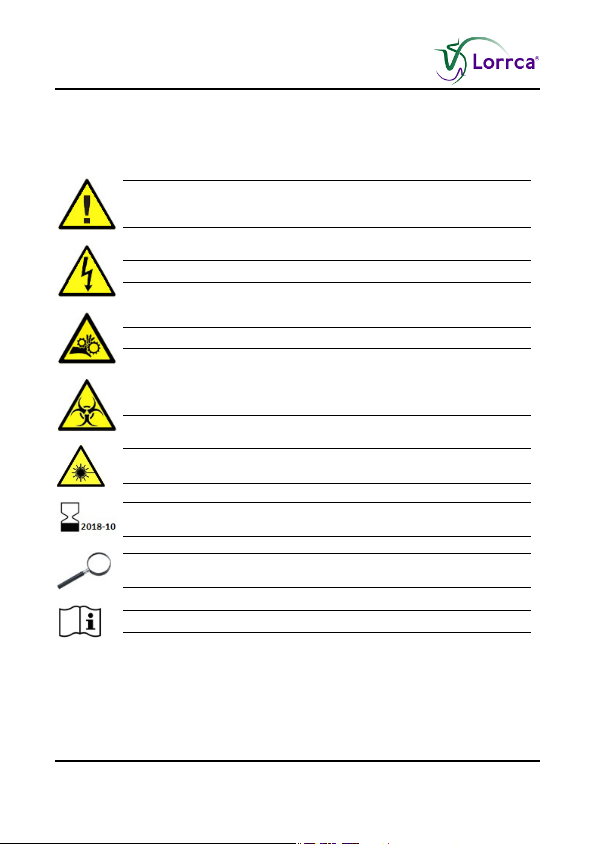
In this manual, the following graphical symbols are used to draw attention to important information:
This symbol indicates warnings and other danger related information. Ignoring this
information could result in personal injury, damage to the instrument or property or
malfunction of the instrument.
Warning sign to prevent personal injury due to electrical shocks
Warning sign to prevent personal injury due to rotating parts
Warning sign to prevent personal injury due to biohazard.
Dangerous laser radiation. Avoid direct exposure to laser beam. Laser safety class
3R
Information sign on the supplied materials intended to inform about the “USE BY”
date.
This symbol indicates useful tips and other important information, that are not
related to any specific danger.
This symbol indicates a reference to this or other product documentation.
Page 14 Lorrca Maxsis User Manual
Version 5.04 MRN-231-EN
Page 17

Instrument description
3. INSTRUMENT DESCRIPTION
The Lorrca® MaxSis consists of the instrument and a control PC with printer. You can find detailed
drawings of the main components in LORC109000 Desk arrangement.
Main components:
1. Computer and display
2. BOB
3. CUP
4. Projection screen
5. De-ionized water bottle, Waste bottle
6. Pumps
7. Valves
8. Laser
9. Osmo High, Osmo Low, Elon ISO bottles
10. Sample unit
Lorrca Maxsis User Manual Page 15
Version 5.04 MRN-231-EN
Page 18
Instrument description
3.1. Instrument label Lorrca® MaxSis
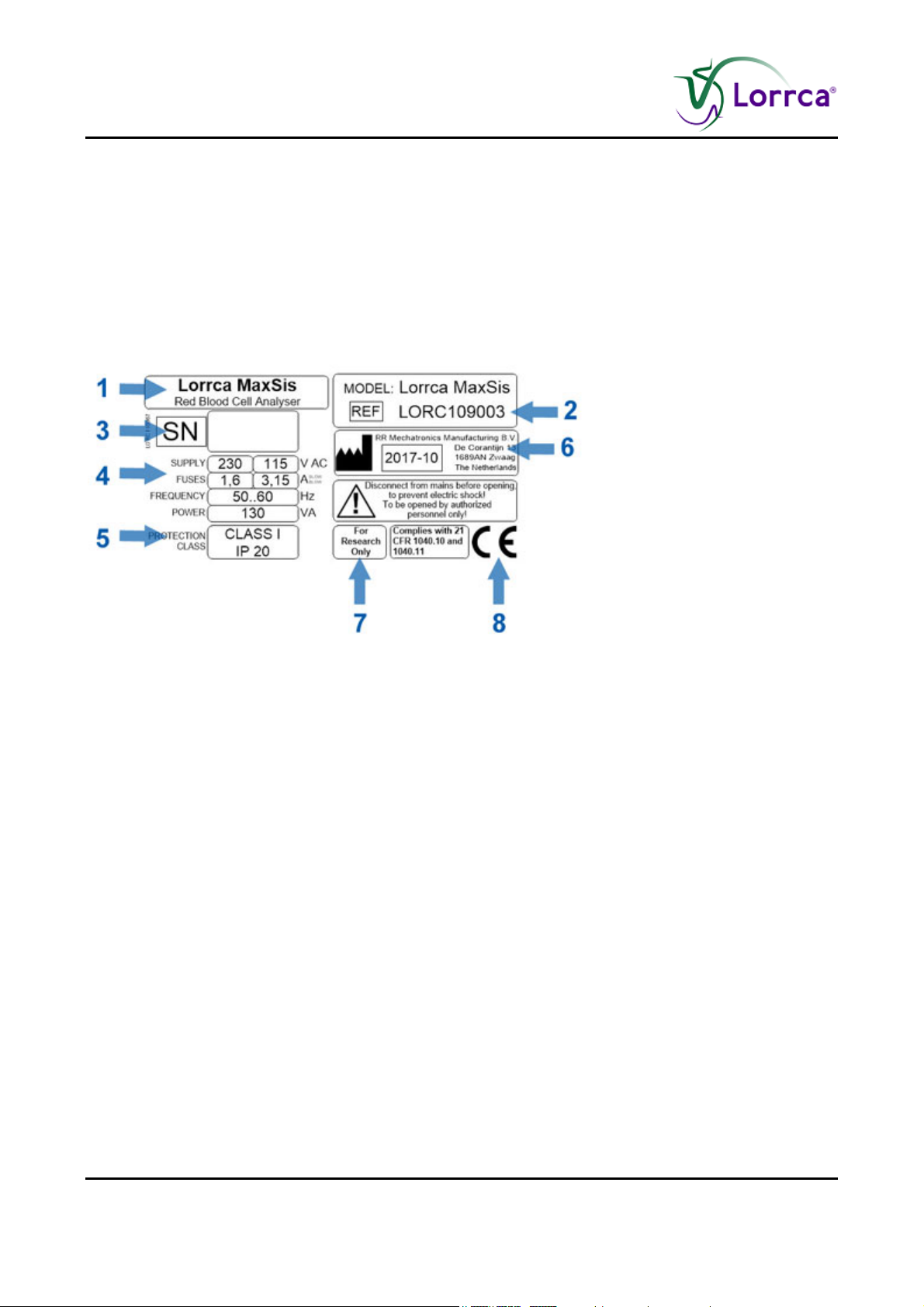
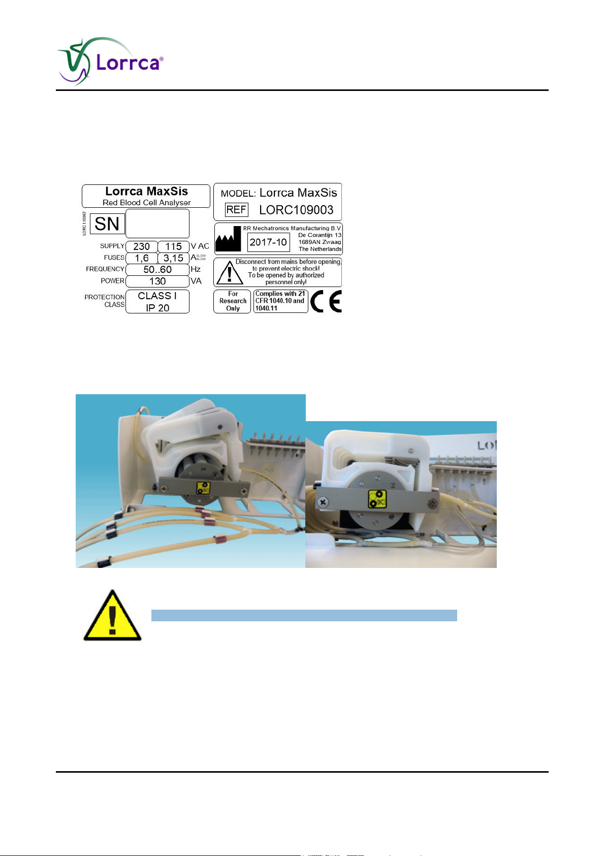
The CE marking and other important information can be found on the Mechatronics instrument
identification plate, an illustration of this is shown below with explanation.
The instrument identification plate is located on the right-hand side of the rear panel of the
instrument under the main switch panel.
Explanation:
1. Name
2. Type
3. Instrument serial number
4. Electrical information
5. Protection class
6. Date of manufacturing
7. Warning(s)
8. Marking(s) and info
Page 16 Lorrca Maxsis User Manual
Version 5.04 MRN-231-EN
Page 19

Instrument description
3.2. Technical specifications
Technical specifications for the Lorrca® MaxSis:
Lorrca® instrument models:
Model
Lorrca® MaxSis LORC109003
Mains voltage
Model name Catalogue number
100/240V 50-60Hz
Fuse (20 x 5 mm)
Slow blow 220V 1.6 Amp
Slow blow 110V 3.15 Amp
Standby 100 VA
Power consumption
Maximum 150 VA
Standby 100 Watt
Heat output
Full operation 150 Watt
Width 470 mm
Dimensions
Height with closed lid 400 mm
Height with open lid 630 mm
Depth 300 mm
70 Kg
Total weight
Width 1000 mm
Min. table size
Lorrca+Laptop Depth 700 mm
< 55 ± 2 dB
Sound level
Working temperature
15 - 35 °C
10 - 90%
Relative humidity
Specifications of other equipment
Objective mount C-mount
Camera
Connection USB 3.0
Minimal resolution 780x582
black/white
Lorrca Maxsis User Manual Page 17
Version 5.04 MRN-231-EN
Page 20

Instrument description
Dimensions 40x40x40 mm
Wave length 655 nm
Laser
Focus distance 170 mm
Blood sample
Tech specs Couette assembly
CUP
BOB
output power Max 3 mW
Tube solution EDTA-Blood
Deformability test
Osmoscan
Oxygenscan
+/- 25 l
+/- 200 l
+/- 50 l
Inner Radius 16.01 ± 0.005 mm
Surface roughness Ra<0.026 µm
Material PMMA
Outer Radius 15.65 ± 0.005 mm
Surface roughness Ra<0.026 µm
Material PMMA
Ambient temperature + 4°C
Drive
Minimal cup speed 0.03 rps
Maximum cup speed 20 rps
Break time from sudden stop from
<30 ms
106 rpm to 0 rpm
0 - 800 s-1
Shear rate
Maximum 2 minutes
Warming-up time Bob
Heating accuracy ± 0.2 °C
Heater
Tech specs Gradient assembly
Range 25 - 45 °C
mixer range 0 - 25 mS/cm
Gradient
Page 18 Lorrca Maxsis User Manual
Version 5.04 MRN-231-EN
mixer accuracy ±-0.5 mS/cm
Reagents 50 - 500 mosm/kg
Page 21

Instrument description
Duration maximum 10
minutes
VC elongation
measurement
Dilution (with full blood) < 200:1 ± 20%
<5% at 3Pa
Lorrca Maxsis User Manual Page 19
Version 5.04 MRN-231-EN
Page 22

Instrument description
3.3. Introduction Lorrca® MaxSis
The Lorrca® MaxSis is a new version of the earlier released Lorca (Laser-assisted Optical
Rotational Cell Analyzer). The Lorrca® MaxSis (Lorrca® hereafter) combines Red Blood Cell
(RBC) deformability by ektacytometry, osmoscan and aggregometry; all temperature controlled. It
is capable of fully automated measurement and calculation of various phenomena of RBC’s by
analysis of their rheological behaviour.
3.3.1. Intended use
The Lorrca® MaxSis is intended for the following measurements on human and veterinary blood
samples:
Red Blood Cell Deformability
Laser diffraction ektacytometry
Relaxation rate
Parametrization of deformation curve
Cell Stability test
Cell Membrane Stability
Red Blood Cell Deformability under various osmotic conditions (Osmoscan)
Osmotic resistance
Red Blood Cell Aggregation
Cell aggregation (kinetics, tendency)
Syllectometry (back-scatter)Disclaimers:
Until otherwise labelled, the Lorrca® MaxSis is NOT released by the manufacturer as an in-vitro
diagnostic medical device (IVD).
Until otherwise published, the Lorrca® MaxSis is NOT validated by the manufacturer for any diagnostic or
therapeutic purposes.
The manufacturer does not accept liability for any consequences arising from the use of the Lorrca®
MaxSis for diagnostic and therapeutic purposes.
Note:
The manufacturer encourages researches who have developed or investigated any possible
diagnostic or therapeutic applications for the Lorrca® MaxSis, to contact the manufacturer in order
to establish and validate the Lorrca® MaxSis as an IVD for these applications.
Page 20 Lorrca Maxsis User Manual
Version 5.04 MRN-231-EN
Page 23

Instrument description
3.3.2. Features of the Lorrca® MaxSis
Only 25 l blood needed for each deformability measurement.
Easy sample changing.
3 mW laser-diode in shielded setup for maximum user safety.
Adjustable shear rates from 0 - 800 s-1.
On-line data analyses and storage via digital camera system.
"On screen" control of diffraction pattern.
Temperature controlled.
Automatic rinsing.
Osmoscan, the instrument is equipped for automatic addition of reagents.
Lorrca Maxsis User Manual Page 21
Version 5.04 MRN-231-EN
Page 24

Instrument description
3.3.3. Symbols
Quantities
Ý
Shear rate (1/s)
Units
Isc
I
Dynamic medium viscosity (mPas; 1 Poise = 100 mPas).
Orientation angle.
Shear stress (Pa; 1 Dyne/cm2 = 0.1 Pa).
Back-scatter intensity (au = arbitrary units).
Intensity parameter resulting from curve fit.
au Arbitrary units.
s
Time, seconds.
Pa Shear stress, Pascal (1 Pa = 10 Dynes/cm2).
mPa.s Dynamic viscosity (1 mPa.s = 1 cP (centi-Poise)).
mm Distance, millimeter.
°C Temperature, degrees Centigrade.
Elongation parameters
A Vertical axis of diffraction pattern (pixels)
B
Horizontal axis of diffraction pattern (pixels).
EI Elongation Index (1).
R Image aspect ratio (%).
Eof
Aggregation parameters
Error of fit (au), average distance of the edge pixels to the best-fit
ellipse.
Isc dis Back-scatter intensity during disaggregation phase (au).
Upstroke
Height of syllectogram upstroke (au).
Isc top Back-scatter intensity of syllectogram peak (au).
Page 22 Lorrca Maxsis User Manual
Version 5.04 MRN-231-EN
Page 25

Instrument description
Isc ½ Back-scatter intensity after one syllectogram half-life (au).
Isc0 Syllectogram base level (au).
Amp
Syllectogram amplitude (au).
AreaA Area above syllectogram (first 10 s) (au*s).
AreaB Area below syllectogram (first 10 s) (au*s).
AI Aggregation Index (%).
t top Time to reach syllectogram peak after cup cessation (s).
t ½
Syllectogram half-life (s)
FSAR Flow to Stasis Aggregation Ratio (1).
Eof
Root of mean square sum of 300 syllectogram samples uniformly
spaced on a log time scale (au).
Ir RBC-shape recovery contribution (au), result of curve fit.
Tr RBC-shape recovery time constant (s), result of curve fit.
If
RBC-rouleaux formation contribution (au), result of curve fit.
Tf RBC-rouleaux formation time constant (s), result of curve fit.
Is RBC-3D aggregate formation contribution (au), result of curve fit.
Ts RBC-3D aggregate formation contribution (s), result of curve fit.
I
Syllectogram base level (au) result of curve fit.
0
Isc max
Ý at Isc
max
dIsc min
Highest back scatter intensity found during iteration procedure (au).
Shear rate (1/s at Isc max.
Lowest back scatter intensity found during iteration with
intermediate disaggregation (au).
ý at min Shear rate (1/s at dIsc min.
Textual
<…>
Text between < > refers to program buttons or to menu items.
NaN Not a Number (when, e.g., a parameter cannot be calculated)
RBC Red Blood Cell
Lorrca Maxsis User Manual Page 23
Version 5.04 MRN-231-EN
Page 26
Instrument description
SD Standard deviation
3.3.4. General measurements description
This section gives a short description of the measurements, for more information see Appendix Additional Information.
3.3.4.1. Principle of operation Lorrca® MaxSis
In order to evaluate the flowing capacity of blood in different parts of the body it is important to
have a technique available for the accurate measurement of Red Blood Cell (RBC) properties.
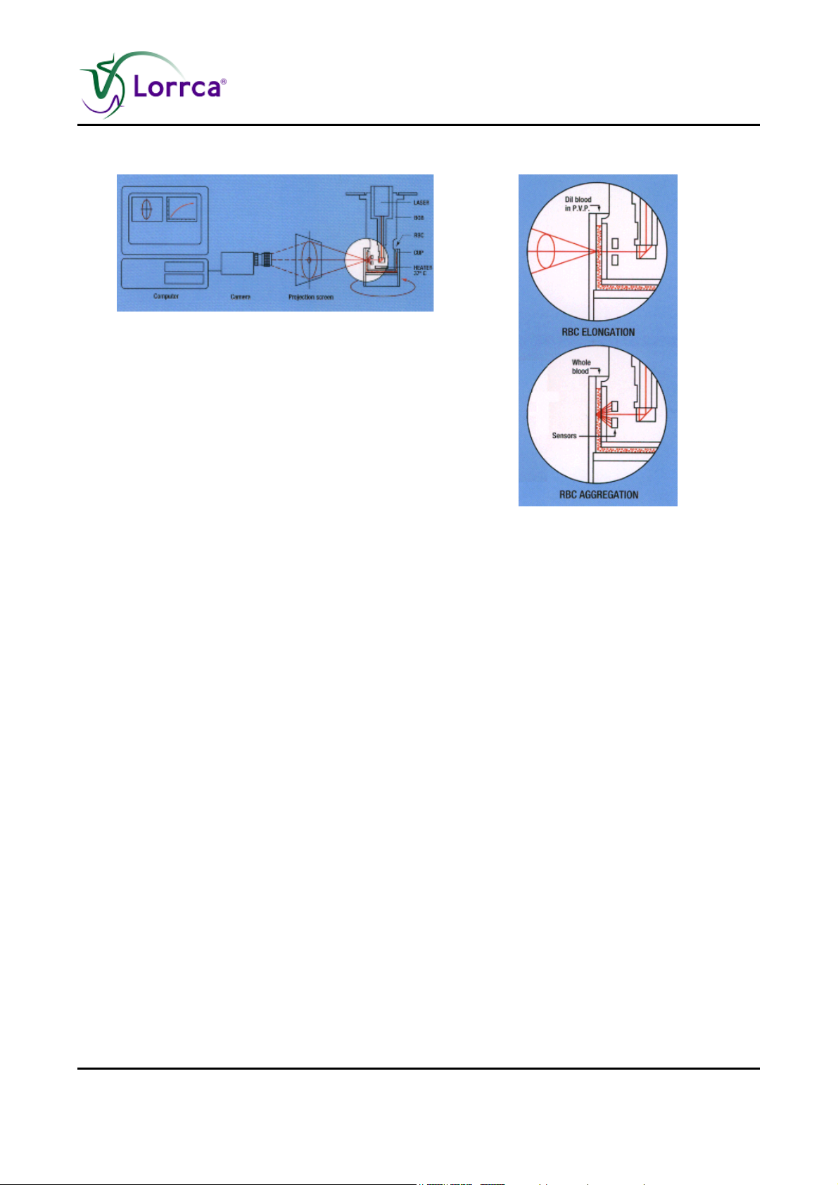
The LoRRca MaxSis is therefore an indispensable instrument. It uses a Couette geometry with a
static BOB and a rotating cylinder (CUP) to create a simple shear flow.
Page 24 Lorrca Maxsis User Manual
Version 5.04 MRN-231-EN
Page 27
Instrument description
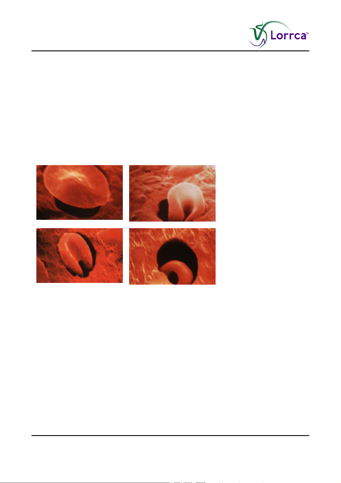
Cell deformability
A thin layer of red blood cell suspension is sheared
between two concentric cylinders. The rotation of the
outer cylinder (CUP), causes deformation (elongation)
of the red blood cells.
The software instructs the operator when to insert the
test suspension, shows the current temperature
during warming-up and performs fully automatic RBC
deformability and stability measurements.
The laser beam diffraction pattern is detected with a
video camera and analysed by a computer.
The RBC elongation program quantifies the following:
Stress dependent (Deformability curve)
Time dependent (Stability test) deformability of red
blood cells
Combination of both (Cell Membrane Stability
Test)
Cell aggregation
Various aggregation indices are determined in whole blood by means of reflection measurements.
The software instructs the operator when to insert the test suspension. A laser diode, mounted in
the BOB, serves as light source. The reflected light is sensed by a photodiode.
The RBC-aggregation software is written for creating the syllectogram and for measuring the
threshold shear rate at which RBC aggregation is just prevented.
The default setting is the tri-exponential model investigator is enabled to select a syllectogramfitting model containing one to three exponents, which describes the whole syllectogram, including
the upstroke. It is possible to change the settings:
The uni-exponential model is interesting to study, e.g., RBC-shape recovery in buffer solution
The conventional bi-exponential model describes the aggregation process while the tri-
exponential model includes both RBC-shape recovery and aggregation
Lorrca Maxsis User Manual Page 25
Version 5.04 MRN-231-EN
Page 28

Instrument description
3.3.4.2. Introduction Osmoscan
The Lorrca® MaxSis has an optional equipment with the possibility for automatic measurement of
Red Blood Cell (RBC) deformability (expressed as elongation index, EI) as a continuous function of
suspending medium osmolality. Both the shape and the position along the osmolality axis of
specific features of these, so called osmoscans provide information about the cell`s deformability
(at the chosen shear stress) as well as their intracellular viscosity and surface-volume ratio. For
characterization of each osmoscan 4 parameters are defined:
Omin (the osmolality at the EI minimum found in the hypotonic region)
EImax (the maximal EI of the total curve)
Omax (the osmolality at EI-max)
Ohyper (the osmolality in the hypertonic region corresponding to 50% of the EI-max).
Application of this approach to a variety of RBC disorders is in line with first generation
ektacytometers.
Osmoscans obtained after various experimental manipulations (heat treatment, exposure to shear
stress and glutaraldehyde) of normal RBC, demonstrating the expected effects.
3.3.4.3. Introduction RBC-elongation
RBC elongation program quantifies the stress dependent (Deformability curve) and time dependent
(Stability test) deformability of red blood cells, or a combination of both (Cell Membrane Stability
Test). The software instructs the operator when to insert the test suspension, shows the current
temperature during warming-up and performs fully automatic RBC deformability and stability
measurements.
3.3.4.4. Introduction RBC-aggregation
RBC-aggregation software is written for measuring the syllectogram and for measuring the
threshold shear rate at which RBC aggregation is just prevented. The software instructs the
operator when to insert the test suspension. The investigator is enabled to select a syllectogramfitting model containing one to three exponents. The uni-exponential model is interesting to study,
e.g., RBC-shape recovery in buffer solution. The conventional bi-exponential model describes the
aggregation process while the tri-exponential model includes both RBC-shape recovery and
aggregation. Unlike other models, the tri-exponential model describes the whole syllectogram,
including the upstroke.
Page 26 Lorrca Maxsis User Manual
Version 5.04 MRN-231-EN
Page 29
Instrument description
3.3.4.5. Introduction Oxygenscan
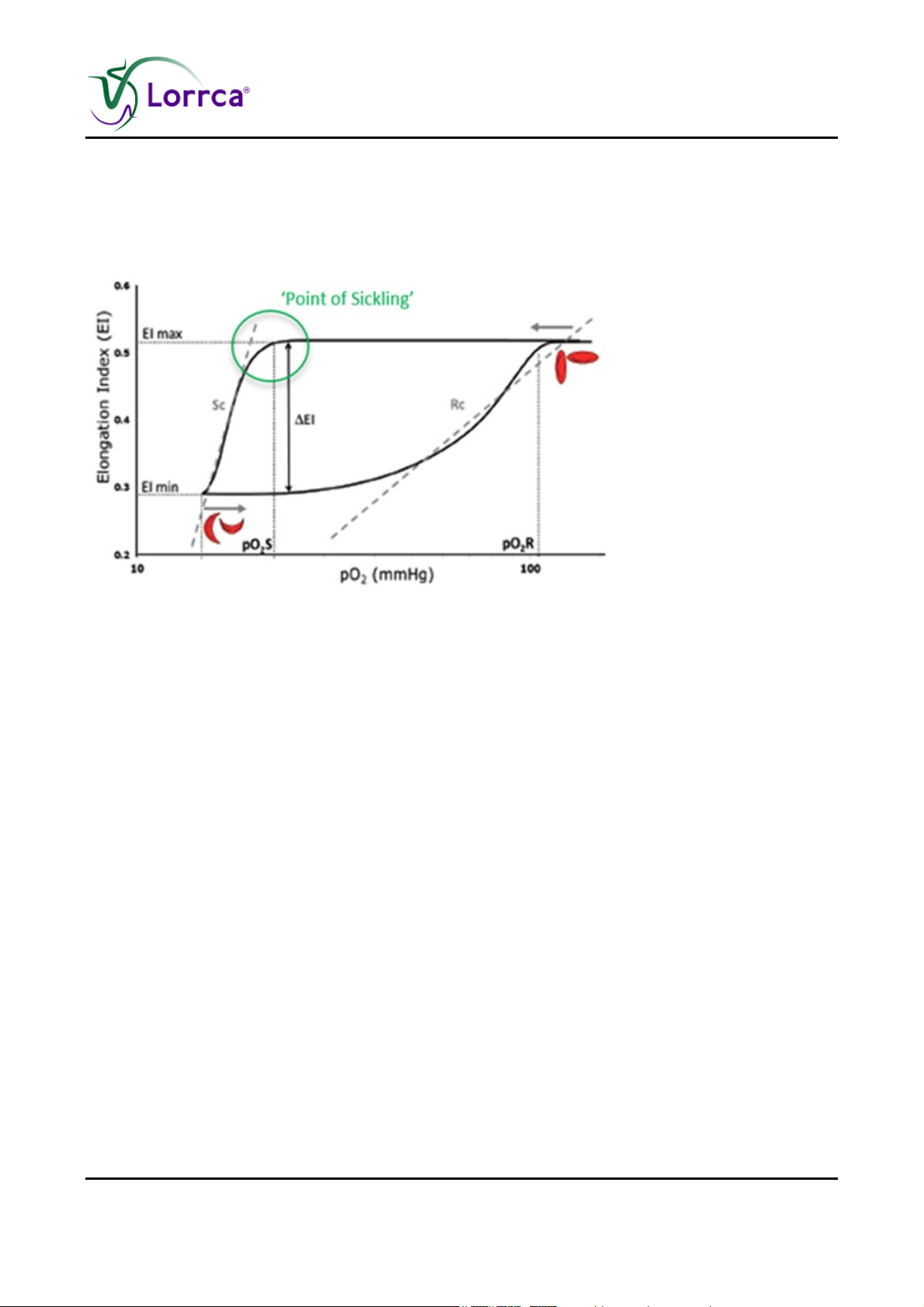
The Oxygenscan measures the relative oxygen pressure at the critical point the RBCs of a SCD
patient start to sickle. This so called "point of sickling" (see Figure. 1) quantitatively and
reproducibly describes the defined loss of deformability of sickle cell disease (SCD) RBCs.
Fig.1 Graphic representation of the measured loss of deformability, the point-of-sickling of SCD RBCs, as a result of oxygen-depletion in time, followed by subsequent gain of
deformability of RBC’s during reoxygenation, as is visualized on the Oxygenscan. It is described by pO2: Oxygen- pressure (controlled, in mmHg), and by EI: elongation index (of the
RBCs in shear rate), in SC RBCs: Sickle Cell patients Red Blood Cells.
Oxygenscan read out parameters are:
EImax, which represents RBC deformability at normoxia;
EImin represents deformability upon deoxygenation;
The point of sickling (PoS), the point at which a >5% decrease in EI is observed during
deoxygenation, reflecting the patient-specific pO2 at which sickling begins (Figure 1).
This PoS is the most characteristic parameters of this measurement. It is typical for each sickle cell
RBC sample (i.e. patient) and sensitive to its status; the PoS shifts due to alteration in treatment.
Supported by the (dynamics of) the change in cell deformability (Elongation index; EI), this
measurement of typical RBC behaviour directly reflects the status of the patients’ susceptibility to
oxygen depletion.
The Oxygenscan measurement represents the ‘whole population’ of RBCs (incl. HbS as well as
HbF containing cells).
Lorrca Maxsis User Manual Page 27
Version 5.04 MRN-231-EN
Page 30

Safety
4. SAFETY
Read this paragraph carefully before using the instrument.
4.1. General safety rules
The instrument described in this manual is designed to be used by properly trained personnel only.
For the correct and safe use of this instrument it is essential that both operating and servicing
personnel follow generally accepted safety procedures in addition to the safety precautions
specified in this manual.
Execute your work according to this manual. Read the instructions before operating the
instrument. Observe all cautionary markings in the manual and on the instrument. Keep this
manual for future reference.
Follow the bio-safety procedures when working with blood-contaminated parts.
Repair can only be executed by trained and qualified personnel.
Wear protective clothing.
When the instrument is running it is not allowed to open the hood.
It is not allowed to give access to the instrument to a non-authorised person at any time.
Whenever it is likely that safety-protection has been impaired, the instrument must be made
inoperative and be secured against any unintended operation. The matter should then be
referred to qualified technicians.
Safety protection is likely to be impaired if, for example, the instrument fails to perform the
intended measurements or shows visible damage or unusual smells, smoke, liquids are flowing
out.
Treat reagents according the material safety data sheets. On our web site the latest version of
Leaflet on material safety data sheets of the used reagents can be found.
Do not spill fluids on to the instrument. This could cause a short-circuit. If this happens, turn the
main switch OFF immediately and unplug the power cable. Contact your service
representative.
Should the instrument emit unusual odours or smoke, turn the main switch OFF immediately
and unplug the power cable. Using the instrument further carries the risk of fire, electric shock
or personal injury. Contact your service representative.
Do not touch the electric circuits inside the instrument particularly with wet hands, as there is a
risk of electric shock.
This instrument must be connected to a power outlet of the correct voltage.
Avoid damage to the power cable. Do not place any appliances on the power cable nor pull on
the power cable.
Page 28 Lorrca Maxsis User Manual
Version 5.04 MRN-231-EN
Page 31

Safety
Use the instrument only for measurements the way described in this manual. The vendor is not
responsible for any damage or harm resulting from incompetent or undocumented use.
Inside the instrument laser light is used for both the elongation and aggregation
measurements. Avoid direct exposure to the laser radiation since this may cause permanent
damage to human tissue. Always close the hood before starting a measurement.
During measurements with the instrument the cup is rotating. Never touch the cup while it is
rotating.
The waste must be treated as potentially infectious (biohazards) material and disposed of
according to local regulations. Check your local environment rules about discharging the waste.
Inside the instrument hazardous voltages reside. Never open the Lorrca® MaxSis. Leave
servicing to qualified service personnel only.
Avoid exposing the instrument to high temperatures (higher than 35°C), direct sunlight or high
humidity (> 80 %).
Before starting work check the technical condition of the instrument and pay particular attention
to:
Protective safety parts: Do they work properly and are they in the correct place.
Loose tubes: Connect them to the right position. See drawing LORC070020 Tubing
diagram (on page 219)
Electrical connections: are they not damaged.
Light: Does it works properly.
Prepare required tools.
Never leave the instrument unattended during work. Refit the protective hood after any
repair and/or maintenance work.
WARNING: Ensure the protective hood is closed during normal
instrument operation!
Lorrca Maxsis User Manual Page 29
Version 5.04 MRN-231-EN
Page 32

Safety
4.2. Electrical safety
The instrument has protective covers, which prevent direct access to the inner parts of the
instrument.
Use only the original delivered main power cord or exact equivalent
The protective covers have the sign:
WARNING: Ensure that covers are closed during normal use.
Always connect to grounded wall sockets.
Set the main switch to the "0" position before opening and/or closing the covers!
Work and/or measurements on the mains power section and other control parts may only be carried out
by properly trained personnel.
Page 30 Lorrca Maxsis User Manual
Version 5.04 MRN-231-EN
Page 33
Safety
4.3. Laser and mechanical safety
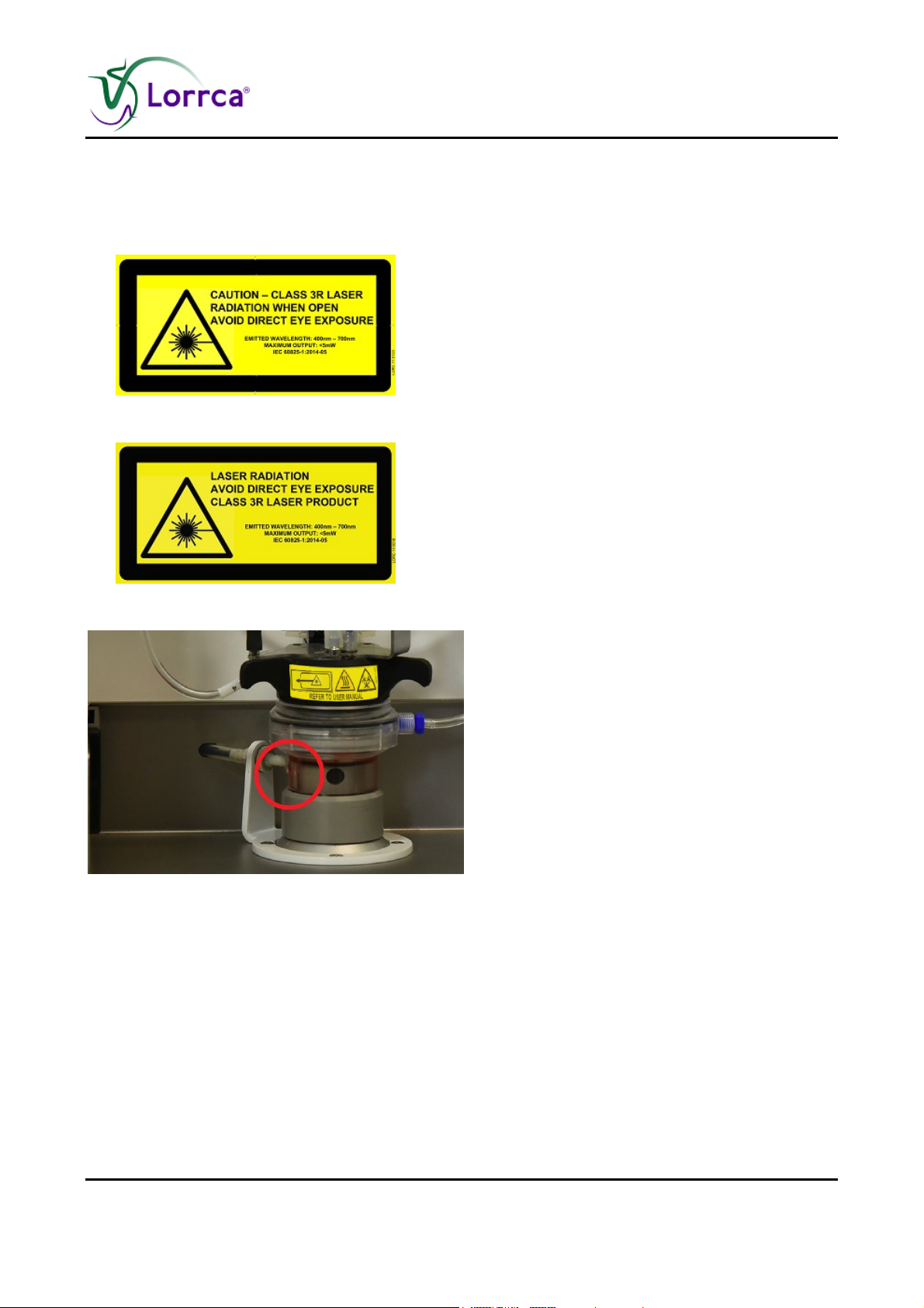
When the hood is open avoid direct eye exposure
The corresponding position of each label on the product indicated:
Label on the outside of the
instrument
This instrument is equipped with a Class 3R laser. Avoid direct eye exposure.
Label inside of the instrument
Be aware of the laser aperture on the left side of the bob.
Lorrca Maxsis User Manual Page 31
Version 5.04 MRN-231-EN
Page 34

Safety
Laser aperture
"CAUTION – USE OF CONTROLS OR ADJUSTMENTS OR PERFORMANCE OF PROCEDURES
OTHER THAN THOSE SPECIFIED HEREIN MAY RESULT IN HAZARDOUS RADIATION EXPOSURE"
A Class 3R laser is considered to be safe if handled carefully, with restricted beam viewing.
EYE INJURY HAZARD -- DIRECT AND REFLECTED BEAM
Do NOT deliberately look into or stare into the beam this can cause injury to the retina.
Be aware of beam reflections off glass and shiny surfaces. Depending on the surface, the reflected beam
could be about as strong and as focused as a direct beam.
The Nominal Ocular Hazard Distance (NOHD) for the applied laser is ~15 centimeter.
The likely closest distance of approach is >20 centimeter (the minimum distance for the eye at which the
laser can be clearly focused on the retina)
4.4. Bio Safety bob assembly
The bob assembly has a combined sign to for laser safety, bio hazard and temperature restrictions.
See for all bio hazard safety instructions chapter Bio safety Standard Operating Procedures
(S.O.P.) (on page 34)
Page 32 Lorrca Maxsis User Manual
Version 5.04 MRN-231-EN
Page 35
Safety
4.5. Safety for working with compressed Nitrogen
Applicable for Lorrca instruments with Oxygenscan
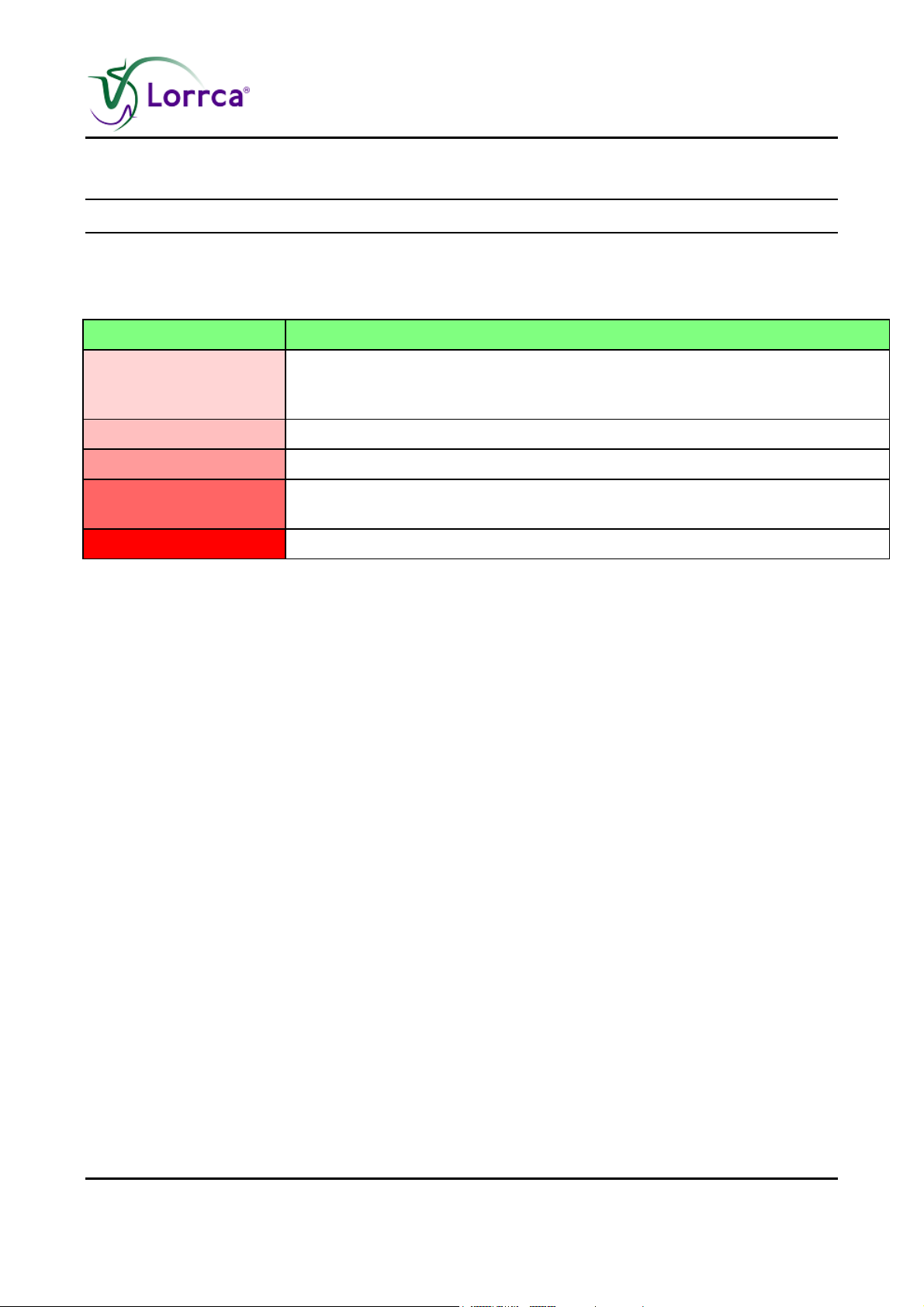
Please be aware of the danger in terms of changing atmospheric levels of nitrogen or oxygen.
The biggest danger to lab personnel is a rapid depletion of oxygen levels in the lab.
O2 (Volume %) Effects and symptoms on exposed
18-21 No noticable effect detected by the individual. Any source of gas contributing
to change in atmosphere should be investigated and assessment carried out
to determine whether environment is safe for continuation of work
11-18 Reduced physical and cognitive function without the individual realising
8-11 Possibility of sudden loss of consciousness. Risk of death below 11%
6-8 Loss of consciousness after a short time period, resuscitation possible if
carried out immediately
0-6 Almost immediate loss of consciousness and brain damage highly likely
An oxygen meter can be used to detect rapid increasing gas levels in the working space.
Lorrca Maxsis User Manual Page 33
Version 5.04 MRN-231-EN
Page 36

Safety
4.6. Bio safety Standard Operating Procedures (S.O.P.)
In this section the following issues can be found:
Basics of Bio safety
S.O.P. for working with bio hazardous materials
If another, more stringent, safety protocol is in place, please adhere to the strictest version.
4.6.1. Basics of bio safety
Basic rules on bio safety in a laboratory;
Wash hands after handling biological materials, after removing gloves and before leaving work
area.
Don't eat, drink, etc. in the work area.
Never mouth pipette.
Take extreme precautions when sharps must be used. Dispose sharps carefully and properly.
Conduct procedures likely to create splashes, sprays, or aerosols within a biological safety
cabinet that is certified annually.
Decontaminate work surfaces at least daily.
Decontaminate waste materials before disposal.
Wear a BUTTONED lab coat to protect your clothes.
Wear gloves when hands may come in contact with potentially infectious materials,
contaminated surfaces, or equipment.
Wear eye/face protection if splashes or sprays are anticipated during work outside a biological
safety cabinet.
Transport materials outside of the laboratory using secondary containment and a cart. Avoid
public areas during transport.
Transfer materials according to federal and international regulations.
Be familiar with written instructions for laboratory procedures and proper responses to
emergencies.
Report spills, exposures, illnesses, and injuries immediately.
Page 34 Lorrca Maxsis User Manual
Version 5.04 MRN-231-EN
Page 37

Safety
4.6.2. S.O.P. for working with bio hazardous materials
Purpose:
To inform and educate all persons that work with biohazards
4.6.2.1. Facts and definitions:
Biological hazards are present in all human and animal tissues and body fluids.
The "normal" research activities carried out in a blood laboratory expose workers to human blood,
urine, sweat, semen, saliva and muscle tissue.
For the purpose of assessing risk, we assume that all volunteers to our clinical studies are not
normal healthy individuals, and take appropriate precautions.
We remain aware at all times that increased knowledge of disease transmission and occupational
hazards may result in situations currently considered safe to be reclassified as having risk.
"Universal Precautions" describes a set of procedures for dealing with subjects based on the
assumption that they are positive for blood borne pathogens. Other precautions are necessary to
prevent exposure to potential respiratory diseases.
4.6.2.2. Medical requirements:
Routine personal medical assessments are advised at regular intervals (yearly) for all personal
exposed to potential biohazard.
Immunisation for Hepatitis B is recommended for everyone who is taking blood samples or dealing
with human blood or body fluids.
4.6.2.3. General laboratory practices:
All users must follow all Departmental Safety Guidelines and bio safety Policy.
Each user is responsible to leave a clean, disinfected and tidy work place.
All biohazard waste must be properly disposed.
Lorrca Maxsis User Manual Page 35
Version 5.04 MRN-231-EN
Page 38

Safety
4.6.2.4. Specific laboratory practices and requirements:
Biohazard waste:
Dispose blood tubes into a biohazard sharps container.
Dispose sharps into a biohazard sharps container.
All other bio hazardous waste is to be deposited into a biohazard bag.
All bio hazardous waste is deposited into the Medical Waste Management (MWM) bin for pick up.
Decontamination procedures:
Routine: At the end of each experiment, or each day, disinfect lab benches and any equipment
Spills: Small spills of biohazard material should be treated by first covering them with an absorbent
paper to avoid the formation of aerosols. Disinfect the spill by slowly pouring on a disinfecting
solution working from the outside to the centre of the spill in a circular motion. Leave the spill long
enough for disinfection to take place (check decontaminating instructions on the disinfectant
container for time) and then carefully wipe up wearing gloves.
Pick up any glass using forceps.
Once all the material has been removed disinfect the area thoroughly.
Inform the Technician in Charge of the spill.
Food:
No food or beverages will be brought into or consumed inside a blood laboratory at any time.
Accident reporting:
All accidents and injuries must be reported within 24 hours to the technician in Charge, to the
Departmental Joint Health and Safety Committee and to the Department of Environmental Health
and Safety using an Incident Report from the main office or the Technician in Charge.
Laboratory access:
Access to the haematology laboratory is limited to persons who are directly involved with the
testing equipment. Children are not permitted in the laboratory.
Personal protective equipment:
Laboratory and maintenance personnel are expected to use a laboratory coat while working in the
blood laboratory.
We advise the use of non-canvas closed-toe shoes wherever there is a potential for foot injury from
hazardous materials or from small physical objects.
Personal outer clothing should not be stored in the blood laboratory.
Lab coats worn in the blood laboratory should not be worn outside of the blood laboratory and
should not be stored with personal outer clothing, to avoid transfer of contaminants.
Gloves are considered contaminated after being worn. Avoid contamination of work surfaces with
gloves. Dispose of gloves into a biohazard container.
The use of eye protection is advised while processing samples.
Remove and properly dispose of gloves and wash hands before leaving the laboratory.
Page 36 Lorrca Maxsis User Manual
Version 5.04 MRN-231-EN
Page 39

Installation
5. INSTALLATION
Installation means: Transport, final assembly, fitting the connections and the starting up of the
instrument. This should only be performed by trained and skilled personnel.
Starting up the instrument and giving instructions for the first (series of) measurements should
always be carried out under the supervision of a Service Technician from the manufacturer or their
representative.
5.1. Pre-installation requirements
Only when pO2 Scan will be used:
Laboratory Integrated Dry Nitrogen Gas Supply (NOT part of accessory set)
consisting of:
Laboratory dry N2 purge system wall socket connection
Low pressure gas tube connection between N2 delivery system and pO2 Scan black tube,
which is the PUN system at 4.0 mm outer diameter.
Flux requirement: gas flow minimal 6 ltr/min, optimal 9 ltr/min
Pressure requirement: pressure larger than 0.8 bar, smaller than 1.0 bar
or
Stand-Alone Cylinder Dry Nitrogen Gas Supply
consisting of:
Pressurized N2 gas cylinder: FOR EXAMPLE UN1066 (F10): Nitrogen 3.0 (purity > 99,9 vol
%), CAS Nr.: 7727-37-9 , EG Nr. (EINICS) : 231-783-9. Max 10 ltr (mandatory for safety).
Lorrca Maxsis User Manual Page 37
Version 5.04 MRN-231-EN
Page 40
Installation
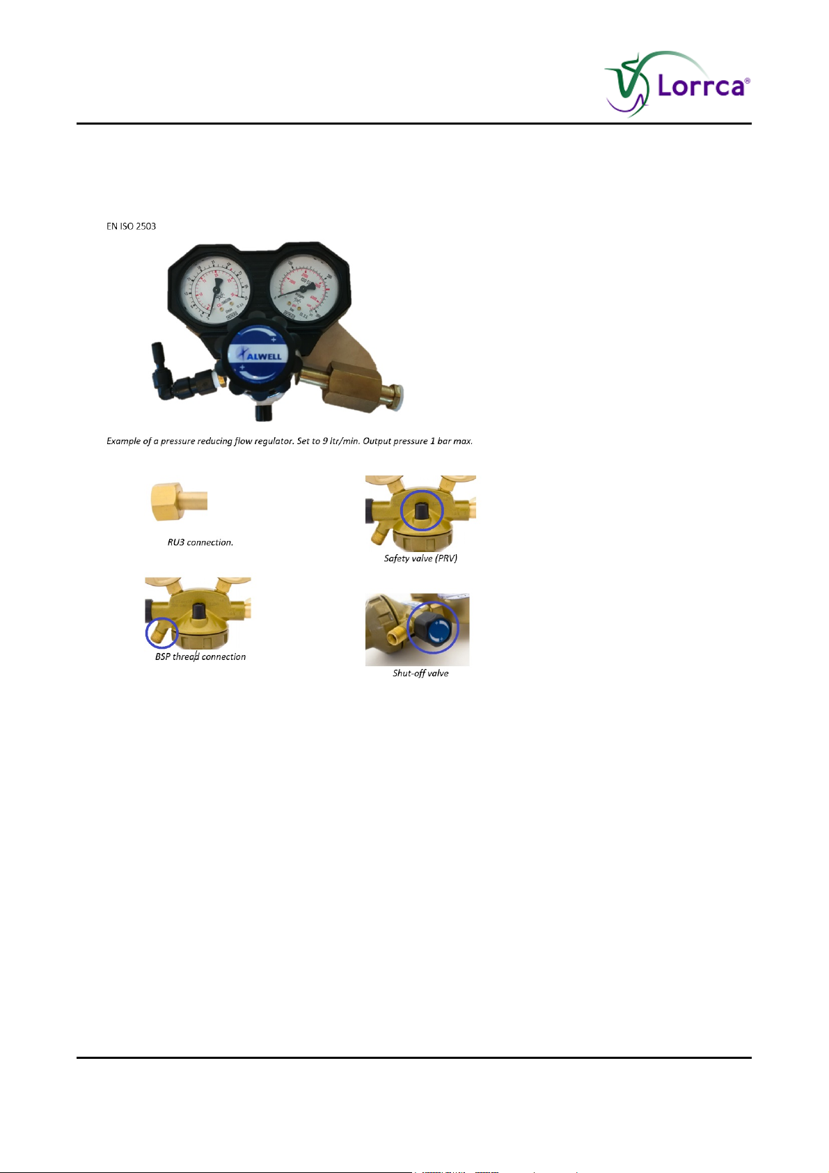
AR-CO2 gas pressure reduction valve / flow regulator: FOR EXAMPLE Alwell type EN ISO
2503 (as depicted) set to 9 ltr/min. Output pressure 1 bar max. RU3 compatible.
Low pressure gas tube connection between pressure reduction valve and pO2 Scan black
tube, which is the PUN system at 4.0 mm outer diameter.
Page 38 Lorrca Maxsis User Manual
Version 5.04 MRN-231-EN
Page 41
Installation
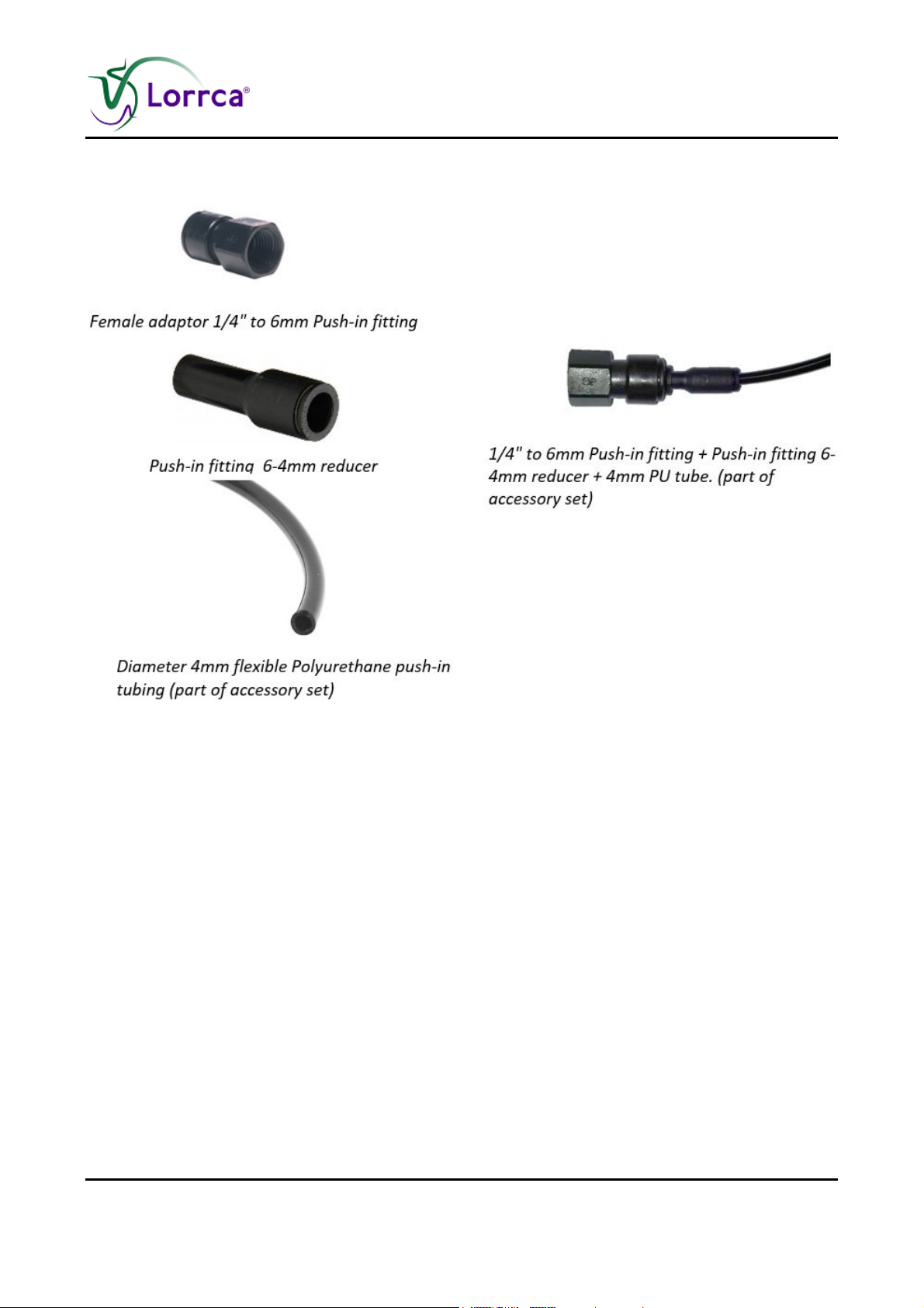
Low pressure gas tube connection
For safety purposes: Oxygen meter
5.2. Transport
When lifting the packaged instrument, take the following information into account:
The total weight of the instrument is 75 kg (including packaging).
The total weight of the reagent box is depending on the ordered amount.
Lorrca Maxsis User Manual Page 39
Version 5.04 MRN-231-EN
Page 42

Installation
5.3. Environmental conditions and setting up the instrument
5.3.1. Conditions
The instrument should be set up on a flat table, level and with sufficient room around it. (see Table
size and or Unpacking/Setting Up (on page 41) for dimensions).
For good operation, the CUP, BOB, bottles, keyboard and mouse should be easily seen and easy
to reach.
It is necessary that the locking protection covers are fully accessible for adjustment and repairs.
WARNING: Always connect to grounded wall sockets.
In order to ensure fault-free operation of the instrument, it is essential that the room where it is
located is temperature controlled.
(The temperature may not be less than 15 °C, nor exceed 35 °C). Keep the area around the
instrument clean and free of dust.
Page 40 Lorrca Maxsis User Manual
Version 5.04 MRN-231-EN
Page 43
Installation
5.3.2. Main power connection
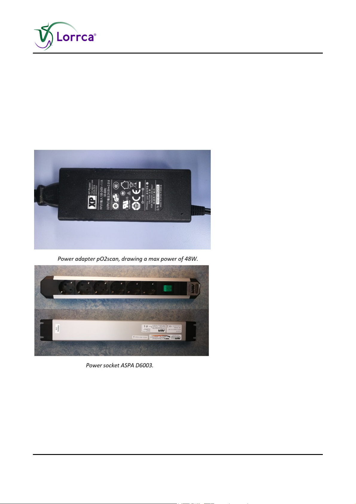
The instrument is delivered with an 10A/230V rated Euro plug lead 10A with locking system for IEC
inlets. Do not replace with inadequately rated cords. Also delivered is an extension socket.
For a 110V connection an IEC Lock PC 1063 120V US power cord can be delivered.
The pO2scan comes along with an additional power strip to make sure both Lorrca + pO2scan can
be powered. The power strip is equipped with a safety switch, enabling the user to power down the
entire Lorrca + pO2scan setup in case of calamities. The pO2scan draws power from a standard
laptop charging power supply.
5.3.3. Unpacking / Setting Up
1. When setting up, take a minimum table space of 700x900 mm in account.
Check for damage during transport.
Lorrca Maxsis User Manual Page 41
Version 5.04 MRN-231-EN
Page 44
Installation
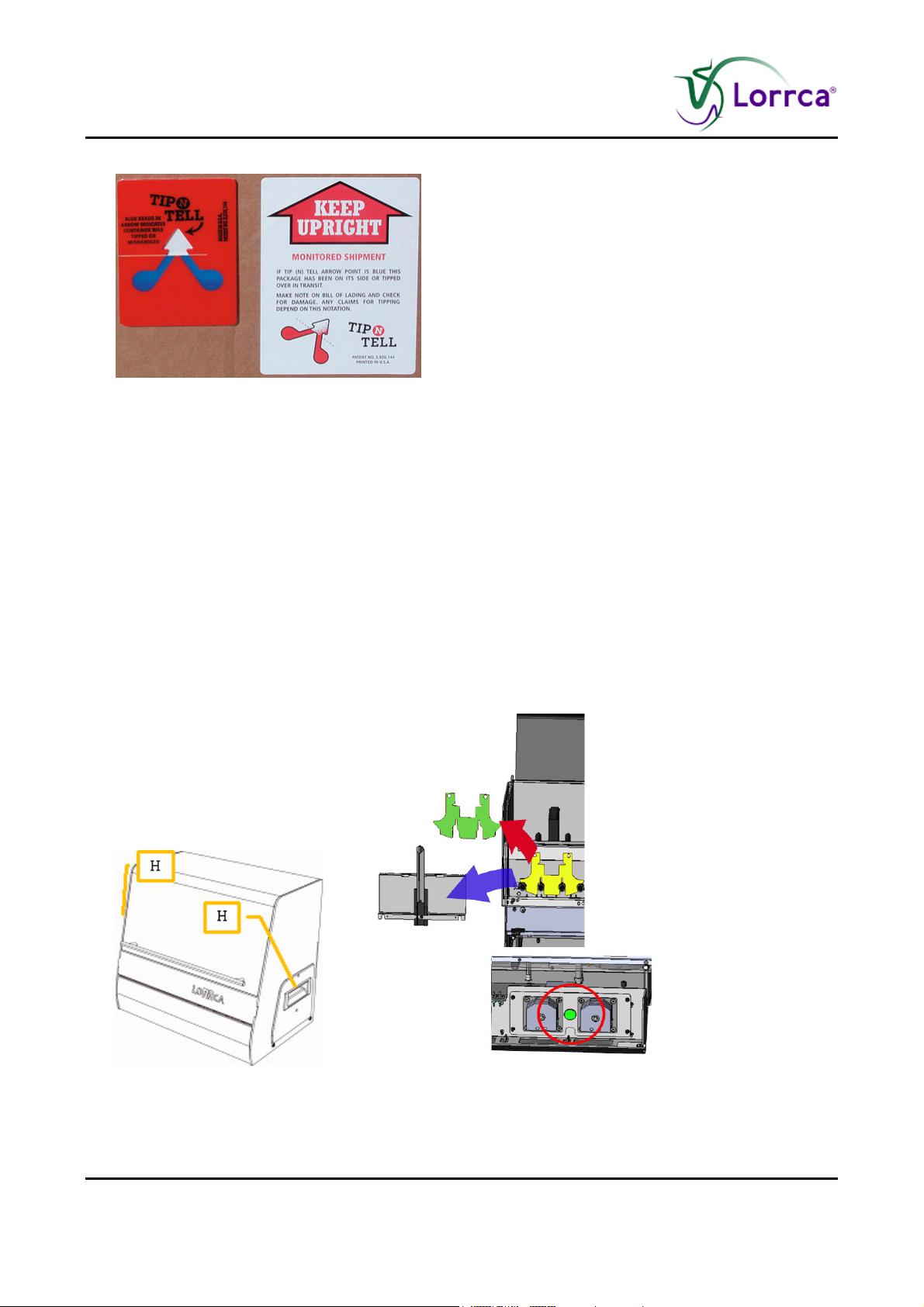
2. Check the Tip N Tell indicator if the packaging has been tipped. If so, act accordingly.
3. Remove the straps from the packaging and open it.
a. Check delivery for completeness;
Lorrca Reagents
b. Printer (if included in order)
c. Lorrca® MaxSis
d. Laptop
e. Accessory kit
4. Take the Laptop, printer and monitor out of the packaging and remove their boxes accordingly.
Place it on the table.
5. Connect the Laptop and Printer cables according the laptop and Printer installation instructions.
6. Take the Lorrca® MaxSis box out of the packaging in upright position and place it on the floor.
7. Open the box and lift the instrument out of the box by grabbing the handles (H) on the sides
(not the hood handle) of the instrument. Place it on the table.
8. Remove the protective materials from the instrument (store them to reuse in case of future
transport);
Foam pieces.
Page 42 Lorrca Maxsis User Manual
Version 5.04 MRN-231-EN
Page 45
Installation
Tie-wraps.
Safety plate on pinch valves
9. Unscrew the bolt from the pump assembly
10. Check/place the correct fuse (F). According ID-plate. Factory default is 230VAC. See section
Replace the main fuses (on page 170)
11. Fill the bottle de-ionized water. Fill the bottles for the Osmoscan.
12. Place the bottles and connect them according the labels. See drawing LORC070020 Tubing
diagram (on page 219)
13. Place tube cassettes of the gradient pump
14. Connect power cables to grounded sockets.
WARNING: Always connect to grounded wall sockets.
Lorrca Maxsis User Manual Page 43
Version 5.04 MRN-231-EN
Page 46
Installation
Connect data cables between the instrument and PC and printer.
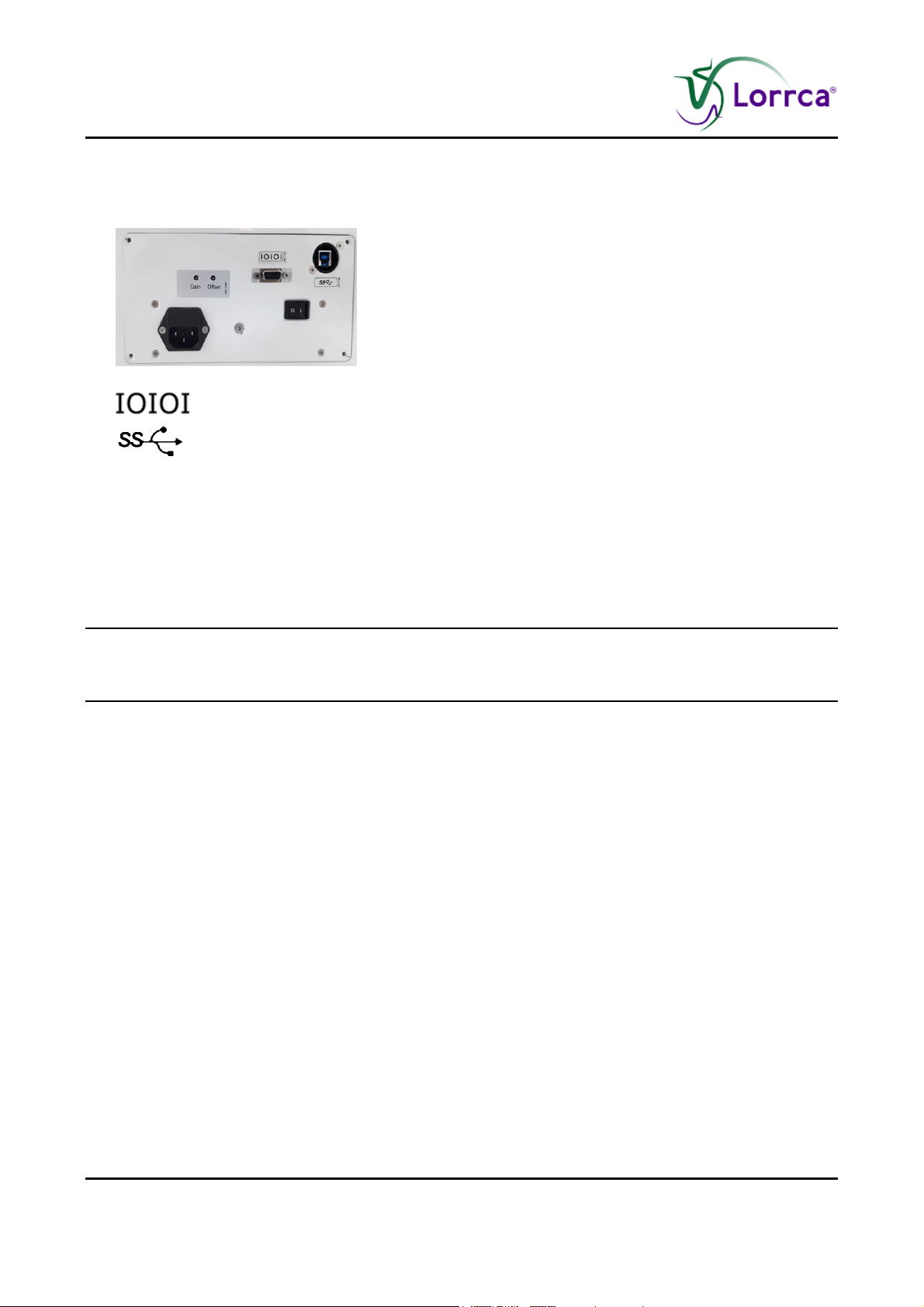
RS232 symbol
Connect camera connection (USB 3.0) on back panel and on the USB port at the right
side of the laptop
Connect the USB-Hub on USB port at the left side of the laptop
For Oxygenscan only: Connect the instrument to a N2-supply with use of the parts from the
accessory set and advised additional material (see Pre-installation requirements (on page
37)).
The Instrument is now ready for first start-up.
Make sure you are familiar with the use of the Lorrca® MaxSis, detailed instructions can be found
in the electronic version of the User manual which is installed on the PC, click on the Manual ICON
to get access to the manual.
Page 44 Lorrca Maxsis User Manual
Version 5.04 MRN-231-EN
Page 47
Installation
5.4. First Start-up
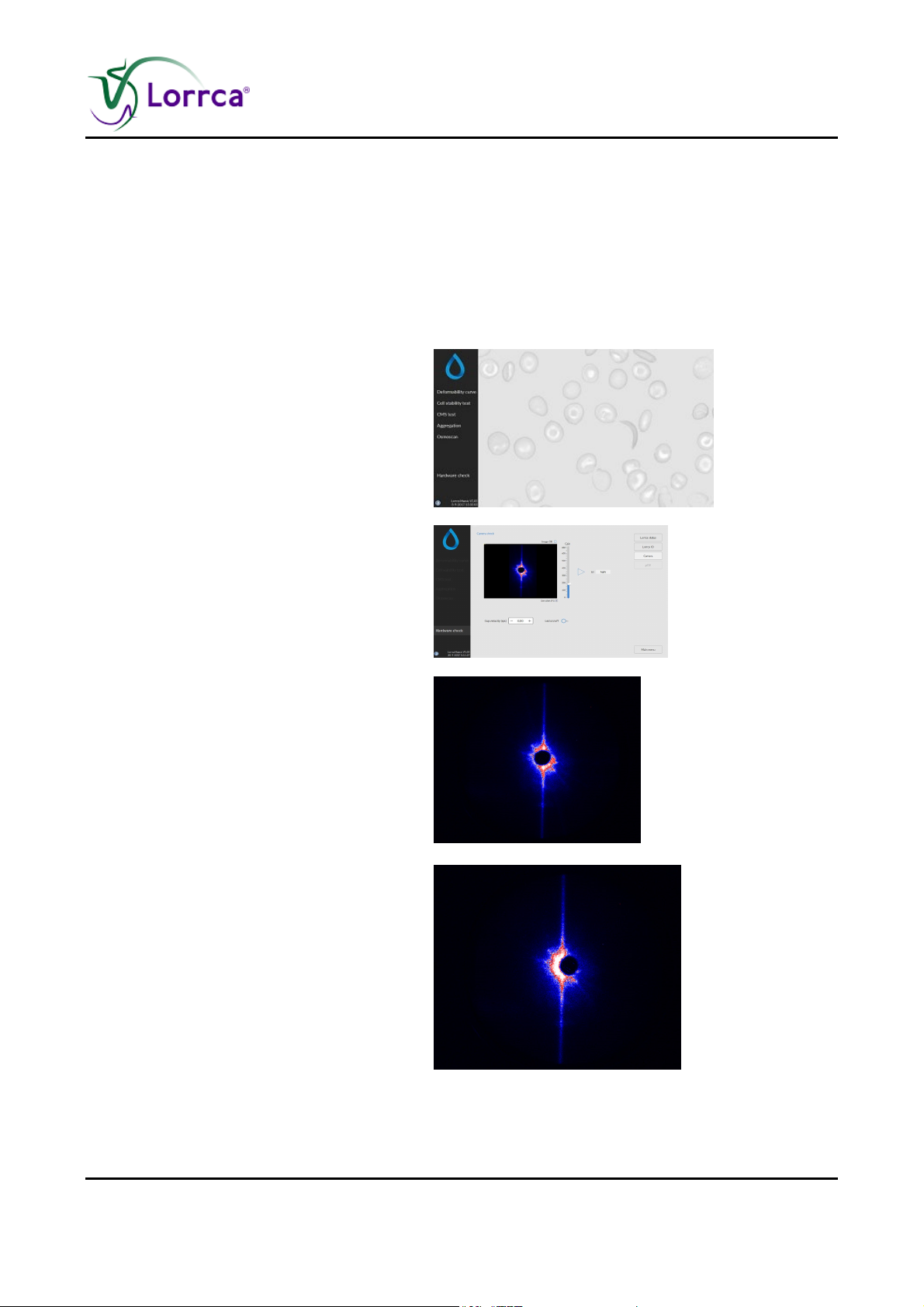
Steady state
After switching on, the Lorrca® MaxSis needs 5 minutes to warm up.
Before the instrument can be operated, you have to carry out the following checks and procedures:
Check that there are no strange objects (tools, for example) in the instrument.
Switch ON the instrument.
Start-up the PC.
Choose LoRRca software program.
Select <HARDWARE CHECK>.
Move the Bob down.
Choose <CAMERA>
Set camera gain at 250.
Close the hood.
Check the image:
OK: The instrument is now ready.
Not OK: Misaligned
Check position of the projection
screen.
Lorrca Maxsis User Manual Page 45
Version 5.04 MRN-231-EN
Page 48
Installation
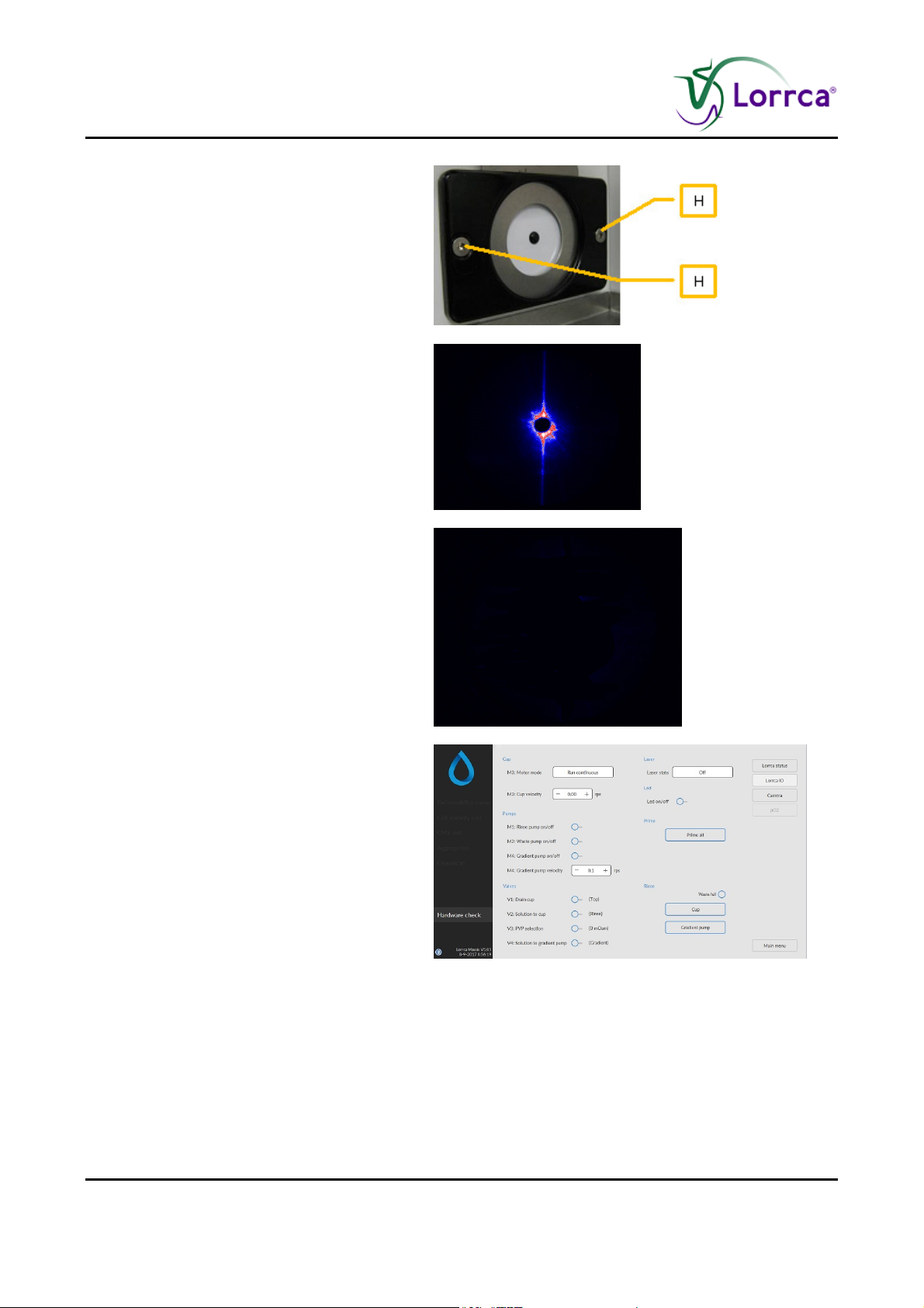
Alignment of the projection screen:
Use the hexagon key 2mm to loosen
the projection screen holder.
Align the projection screen until the
black dot on the screen is aligned with
the laser spot. Note: The projection
screen holder itself can also be
adjusted (equipped with slotted holes)
Tighten the screws of the projection
screen holder.
Not OK: Driver failure.
Update the camera driver. See
Camera driver installation (on page
156)
Choose <LORRCA IO><RINSE CUP> and
confirm.
The tubes are being filled.
Dry BOB and CUP. Do not scratch the cup
and do not touch the glass with your
fingers to prevent staining! Pay attention to
the hole in the BOB.
After this procedure, the instrument is in the start position.
Page 46 Lorrca Maxsis User Manual
Version 5.04 MRN-231-EN
Page 49

Installation
5.5. Checking Lorrca® MaxSis functionality
Both the elongation and aggregation program feature a “check” window that can be used to test
the hardware functions individually:
LoRRca status
LoRRca IO
Camera
The adjustments made with this checking feature are only temporary and will be restored to default
when closing the check window.
Lorrca Maxsis User Manual Page 47
Version 5.04 MRN-231-EN
Page 50
Installation
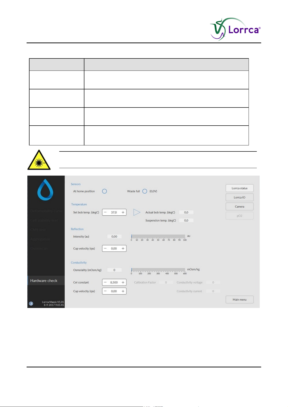
5.5.1. Instrument status
Function Description
At home position
Intensity (au)
LED is lit when CUP is at home position (= fixed position along cup
circumference where back-scatter intensity is acquired)
Back-scatter intensity (arbitrary units), should be within the range [0,
100] au during measurements (when blood is inserted).
BOB temperature Current BOB temperature in degrees Centigrade
Run motor at (rps)
Motor control. Set to desired cup revolution speed (rps = revolutions
per second).
During this test, the laser is turned on (flash) in order to enable back-scatter
intensity measurements.
Page 48 Lorrca Maxsis User Manual
Version 5.04 MRN-231-EN
Page 51
Installation
5.5.2. Lorrca IO
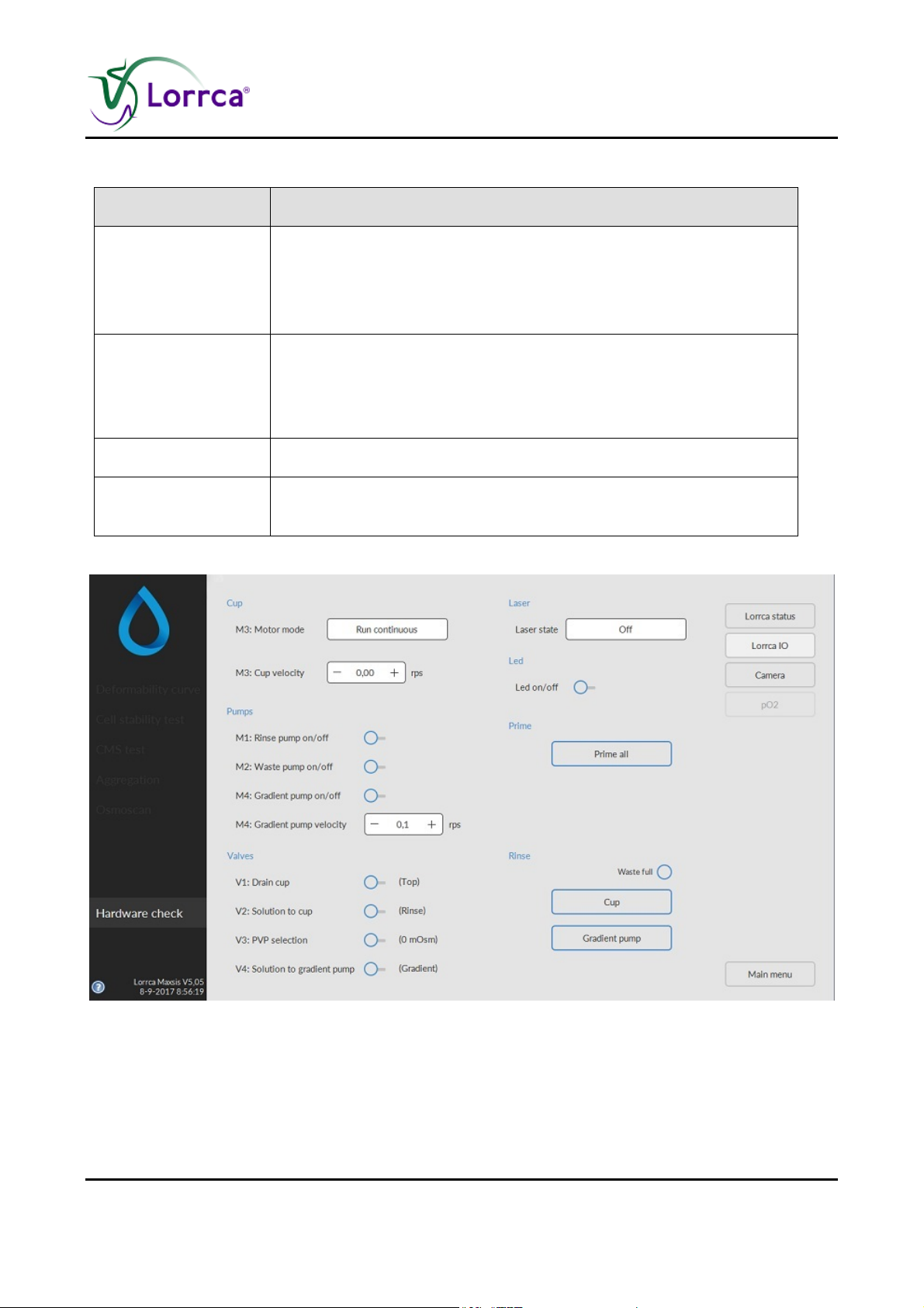
Function Description
Control to select one of the following laser states:
Laser state
1. On, continuous
2. On, Flash (Modulated)
3. Off.
Control to select one of the following motor modes:
Motor mode
1. Run until in home position,
2. Run continuous. If in the home position, the motor can be reactivated by changing any of the other motor parameters.
Run motor at (rps) Sets motor revolution speed
Valves
With toggling ON/OFF the functioning of the pinch valves can be
checked (each valve should give a "click")
Lorrca Maxsis User Manual Page 49
Version 5.04 MRN-231-EN
Page 52
Installation
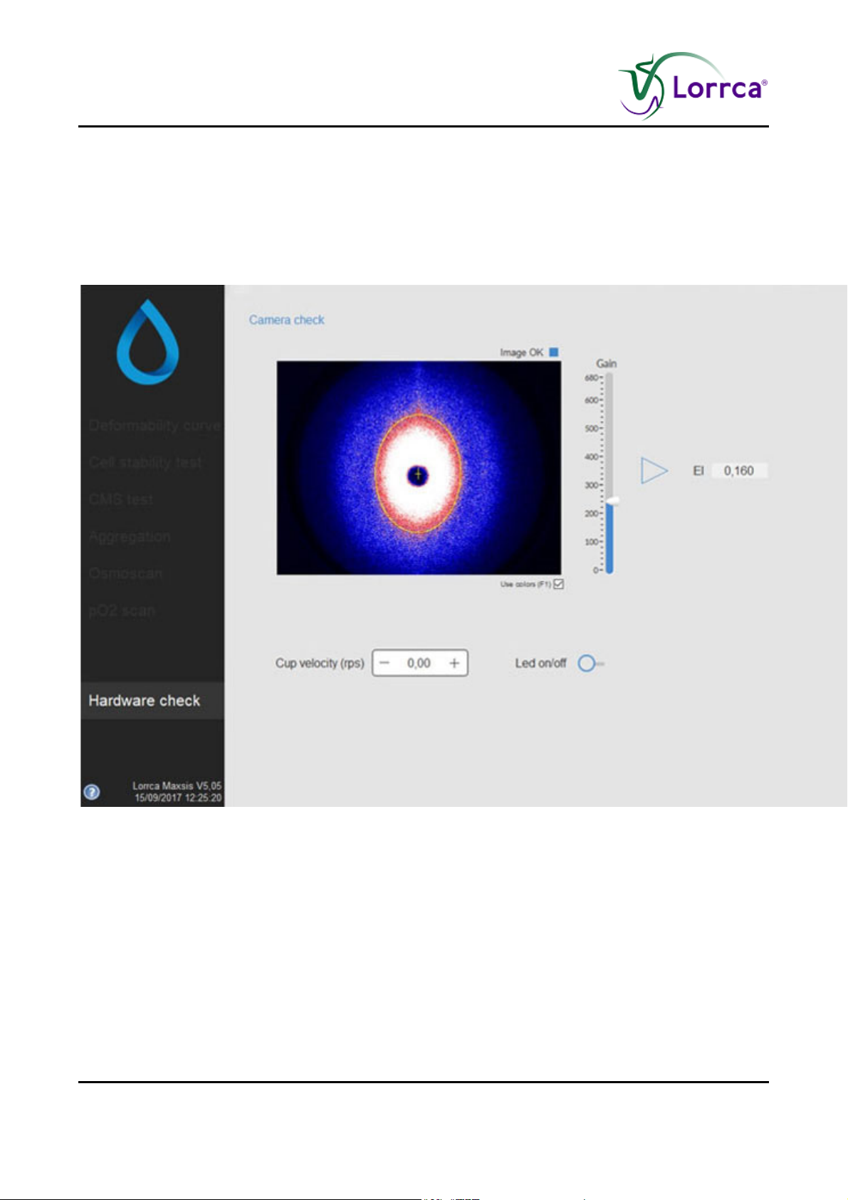
5.5.3. Camera
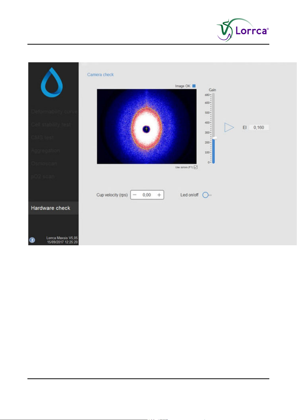
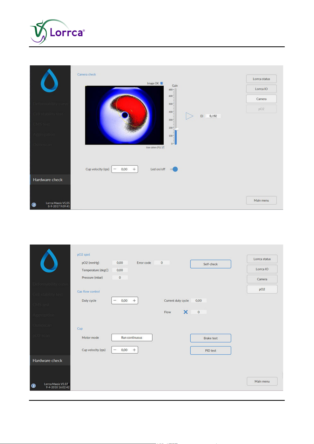
With this test, the laser is turned ON (continuous) and the motor speed is maintained as set in any
of the other tabs. The image shows a coloured version of the diffraction pattern (see screen). The
“Use colors” check box can be cleared to view the underlying gray scale image.
Page 50 Lorrca Maxsis User Manual
Version 5.04 MRN-231-EN
Page 53
Lorrca MaxSis Program
6. LORRCA MAXSIS PROGRAM
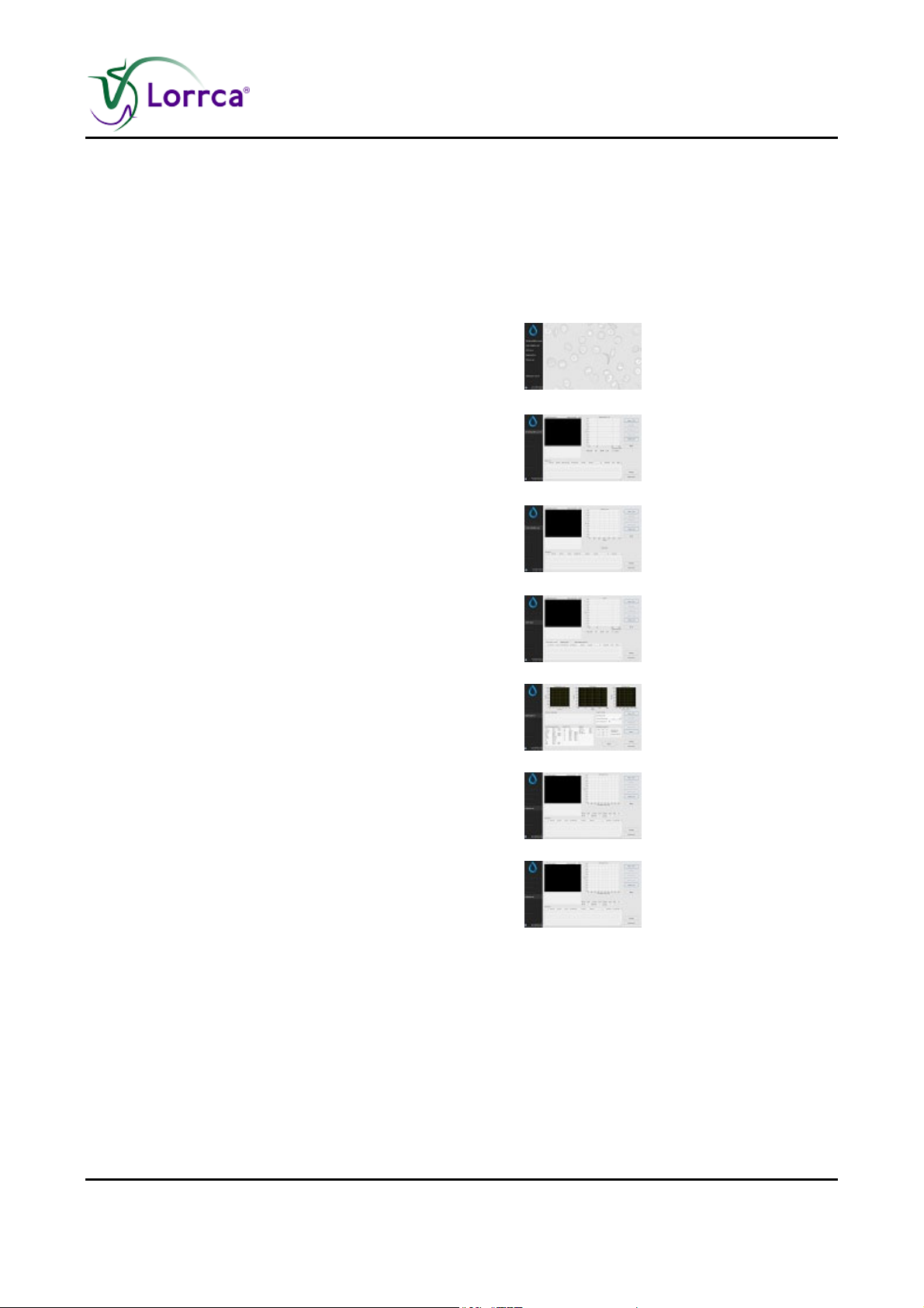
The Lorrca® MaxSis is controlled via an external computer that runs the Lorrca® MaxSis program
and controlled by mouse pointer.
The following type of measurements can be selected from the main screen:
Default screen is the Main screen (on page 52)
Deformability curve determination screen (on page
78)
Stability Curve determination screen (on page 85)
Cell Membrane stability screen (on page 88)
RBC aggregation screen (on page 96)
Osmoscan screen (on page 73)
Oygenscan screen (on page 81)
Lorrca Maxsis User Manual Page 51
Version 5.04 MRN-231-EN
Page 54
Lorrca MaxSis Program
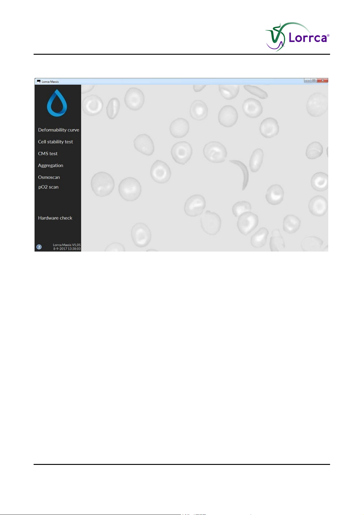
6.1. Main screen
6.2. Main screen settings
Page 52 Lorrca Maxsis User Manual
Version 5.04 MRN-231-EN
Page 55
Lorrca MaxSis Program
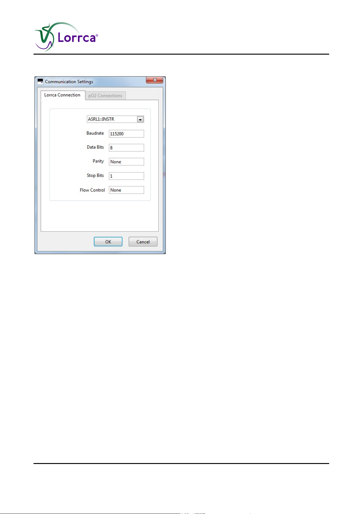
6.2.1. Screen communication settings
OMMUNICATION SETTINGS: Select the output port for communication.
C
Lorrca Connection
1. Serial output comport.ASRL1::INSTR. By default
2. Baud rate. Selectable 1200, 4800 ,9600, 38400 and many more default is set on 115200
3. Data bits. Selectable 7 or 8 data bits
4. Party bit: Selectable none, space, mark, even and odd
5. Stop bits: Selectable 1, 1.5 or 2 stop bits
6. Flow control: Selectable for;
None
XON/XOFF
RTS/CTS
DTR/DSR
XON/XOFF & RTS/CTS
XON/XOFF & DTR/DSR
pO2 Connection
Lorrca Maxsis User Manual Page 53
Version 5.04 MRN-231-EN
Page 56

Lorrca MaxSis Program
6.2.2. End of the day wash screen
When the program is shut down a pop-up screen appears with “End of day wash” message. To
perform an End of day wash exchange the rinse bottle with the cleaning solution bottle and follow
the software instructions.
6.3. Hardware check status
Page 54 Lorrca Maxsis User Manual
Version 5.04 MRN-231-EN
Page 57
Lorrca MaxSis Program
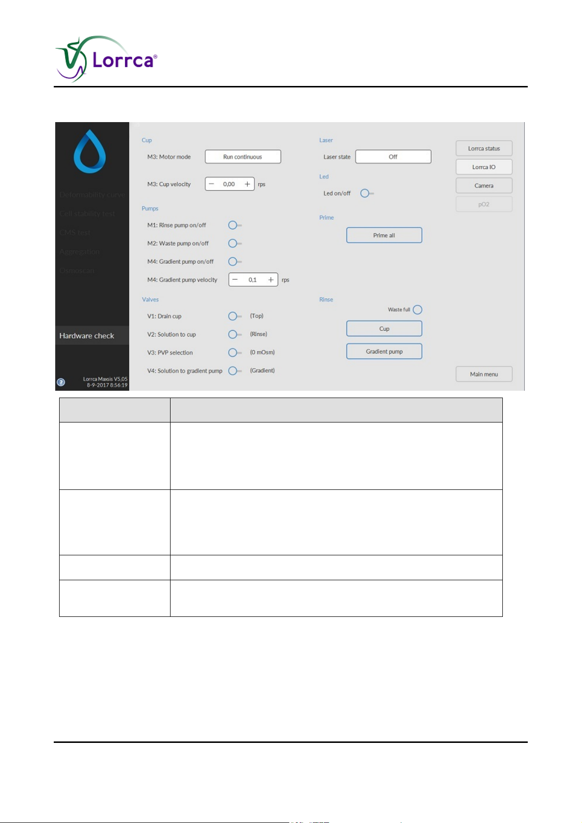
6.3.1. Hardware check IO screen
Function Description
Control to select one of the following laser states:
Laser state
1. On, continuous
2. On, Flash (Modulated)
3. Off.
Control to select one of the following motor modes:
Motor mode
1. Run until in home position,
2. Run continuous. If in the home position, the motor can be reactivated by changing any of the other motor parameters.
Run motor at (rps) Sets motor revolution speed
Valves
With toggling ON/OFF the functioning of the pinch valves can be
checked (each valve should give a "click")
Lorrca Maxsis User Manual Page 55
Version 5.04 MRN-231-EN
Page 58
Lorrca MaxSis Program
6.3.2. Hardware check Camera screen
Page 56 Lorrca Maxsis User Manual
Version 5.04 MRN-231-EN
Page 59
Lorrca MaxSis Program
6.3.2.1. Hardware check Camera Led on screen
6.3.3. Hardware pO2
Lorrca Maxsis User Manual Page 57
Version 5.04 MRN-231-EN
Page 60
Lorrca MaxSis Program
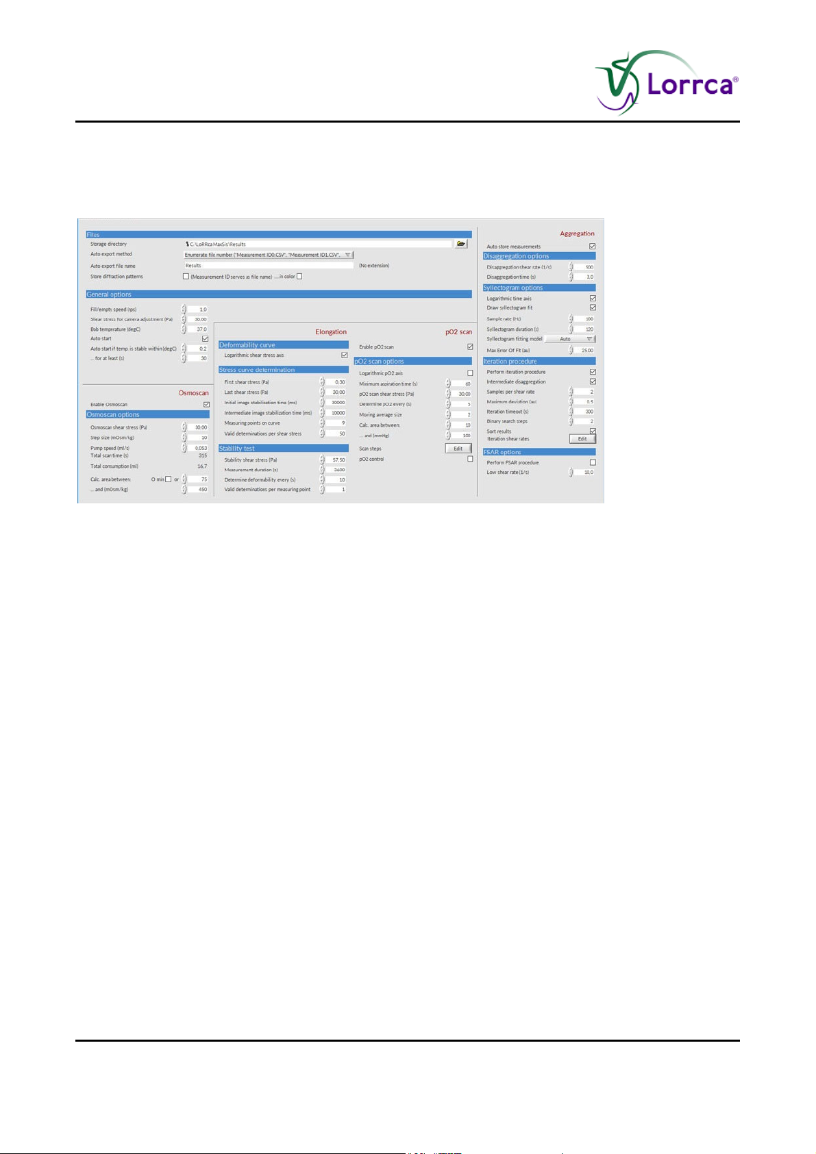
6.4. Settings screen
Before a measurement can be started check if the chosen settings are the appropriate ones, either
the default settings or customized settings.
You can always revert to the factory default settings by choosing <F
ILE ->LOAD DEFAULT>
Page 58 Lorrca Maxsis User Manual
Version 5.04 MRN-231-EN
Page 61

Lorrca MaxSis Program
6.4.1. Files
Settings Description
Storage directory Location for storing result files (measurements, diffraction
pattern images). If a "relative" path/name is given, it starts from
the program directory.
Auto export method Method for storing measurement results (as Comma Separated
Values (CSV) files):
<N
O EXPORT>
The results of the last measurement are always available from
file "Auto export file".CSV". This file is overwritten after each
measurement.
<C
ONCATENATE RESULTS TO SINGLE FILE>
With this selection measurements results are always added to a
file named "NameHistory.CSV". Some text editors or
spreadsheet programs cannot read extremely large CSV-files. It
is therefore advisable to backup and delete this file from the
hard disk regularly, before its size exceeds the applicable
maximum.
Auto export file name
Store diffraction
patterns
<E
NUMERATE FILE NUMBER>
With this selection, each measurement is stored in a separate
file with a name being equal to the patient name (as entered in
the "Insert blood sample dialog"). Additional measurements for
the same patient, will be stored with an enumeration number
[0..n]. For example, the first result file of patient Jones is stored
as Jones_0.CSV, the next as Jones_1.CSV and so on.
Name of the file (with extension ".CSV") that holds the last
measurement results. If the "Auto export method" is set to
"Concatenate results to single file", the name is also used to
create the name of the file containing the measurement history.
Checkbox to enable storing diffraction patterns. Only diffraction
patterns are stored that include the actual measurement, i.e.,
not those during camera adjustment.
Lorrca Maxsis User Manual Page 59
Version 5.04 MRN-231-EN
Page 62

Lorrca MaxSis Program
6.4.2. General options
Settings parameter Description Range
Fill empty speed (rps) Cup revolution speed (revolutions per
second) used at the moment of inserting or
removing the test suspension.
[0.1, 10] rps
Shear stress for camera
adjustment (Pa)
Shear stress applied during camera
adjustment (diaphragm).
Bob temperature (°C) Desired bob (and hence, suspension)
temperature in degrees Centigrade.
Auto start if temp. is stable
within (°C)
If temperature is within ± 0.2 °C, the
measurement starts after the value given
at parameter ... for at least (see next)
… for at least (s) Time to automatic start
6.4.3. Elongation
6.4.3.1. Deformability curve Parameters
Settings parameter Description
Logarithmic shear stress
axis
Checkbox Turns this option on/off
[0, 100] Pa
[20, 45] °C
[0.1, 10] °C
[5, 300] s
Page 60 Lorrca Maxsis User Manual
Version 5.04 MRN-231-EN
Page 63

Lorrca MaxSis Program
6.4.3.2. Stress curve determination Parameters
Settings parameter Description Range
First shear stress (Pa)
First and last shear stress to apply during the
[0.01, 100]
determination of the deformability curve. By taking
Last shear stress (Pa)
"First" higher that "Last", the curve will be completed in
reverse order.
Pa
Initial image
stabilisation time (ms)
Intermediate image
stabilisation time (ms)
Measuring points on
curve
Valid determinations
per shear stress
Following camera adjustment at a high shear stress,
the measurement starts with the "first measurementshear stress", described above. The cells in the
suspension need time to adjust to each new shear
stress, especially when the shear stress for camera
adjustment is high compared to the first measurementshear stress. This parameter defines the initial cell
stabilisation time following camera adjustment. If the
standard deviation of the elongation measurement at
the first measurement-shear stress is still quite high,
the initial stabilisation time may need to be increased.
Like the stabilisation time mentioned in the former
parameter description, the cells in the suspension need
time to adjust to each new shear stress. This
parameter defines the time for stabilisation of the
suspension between subsequent elongation
measurements.
Determines the number of shear stresses that are used
to build up the deformability curve.
Prescribes the number of subsequent EI
determinations (each from a newly acquired diffraction
image) to find the average EI (and SD) per shear
stress.
[0.1, 600] s
[0.1, 600] s
[2, 2000]
[2, 1000]
Lorrca Maxsis User Manual Page 61
Version 5.04 MRN-231-EN
Page 64

Lorrca MaxSis Program
6.4.3.3. Stability test parameters
Settings parameter Description Range
Stability shear stress
(Pa)
Shear stress used during the stability test (Pa)
[0.01, 100]
Pa
Measurement duration
Duration of stability test.
[1, 100000] s
(s)
Determine
deformability every (s)
Time that elapses before performing another
deformability measurement (diffraction pattern
[1, 3600] s
analysis).
Valid determinations
per measuring point
Prescribes the number of subsequent EI
determinations (each from a newly acquired diffraction
[1, 200]
image) to find the average EI (and SD) per
deformability measurement.
6.4.4. Aggregation
This section gives a short description for all Settings parameters that influence the way
aggregation measurements are performed.
Settings parameter Description
Auto store
measurements
Checkbox Turns this option on/off
6.4.4.1. Disaggregation options
Settings parameter Description Range
Disaggregation shear
rate (1/s)
disaggregation time (s)
This disaggregation shear rate and time apply
throughout the aggregation measurement
procedure:
1. Before measuring the syllectogram,
[5, 2500] /s
[0, 3600] s
2. For intermediate disaggregation during the
iteration procedure.
3. Just before applying the "Low shear rate" during
the FSAR measurement.
Page 62 Lorrca Maxsis User Manual
Version 5.04 MRN-231-EN
Page 65

Lorrca MaxSis Program
6.4.4.2. Syllectogram options
Settings parameter Description Range
Logarithmic time axis Check to obtain a logarithmic time scale for the
syllectogram. Remove check mark for linear time
scale.
Checkbox
Draw syllectogram fit
Sample rate (Hz)
Syllectogram duration
(s)
Syllectogram fitting
If checked, the syllectogram is superimposed by the
result of exponential fitting, using the selected
"Syllectogram model (see below).
Number of samples to take per second when
measuring the syllectogram curve. Must be high
enough to record fastest details (the peak) of the
syllectogram.
Syllectogram measurement duration.
A
UTO:
In auto-mode, all models are evaluated and the
program will present the best fitting model. The
result of other models can still be examined and
printed.
Mathematical model used to fit the syllectogram:
Tri-exponential (rise-fall-fall)
Bi-exponential (rise-fall)
Bi-exponential (fall-fall).
Checkbox
[10, 1000] Hz
[1, 3600] s
-
Uni-exponential (rise)
Uni-exponential (fall)
See Appendix Additional Information section Triexponential syllectogram representation (on
page 208)
Max Error Of Fit (au) It is evaluated whether or not each of the fitting
models was successful from the error-of-fit
parameter (EOF). Since the syllectogram is sampled
uniformly most data points stem from the tail of the
curve. To prevent the fitting algorithm from focusing
on this region, the curves were re-sampled by
selecting 300 points uniformly distributed on a
logarithmic time scale. The EOF is defined as the
root of the mean square sum of these 300 samples.
Lorrca Maxsis User Manual Page 63
Version 5.04 MRN-231-EN
[0.01, 100] au
Page 66

Lorrca MaxSis Program
6.4.4.3. Iteration parameters setting
Settings parameter Description Range
Perform iteration
procedure
Intermediate
disaggregation
Samples per shear
rate
Maximum deviation
(au)
Checkbox, to include the iteration procedure for the
determination of the threshold shear rate (see
Appendix). The iteration procedure is determined
following measurement of the syllectogram. During
iteration, only one sample is taken per cup
revolution to avoid optical disturbances.
Checkbox to disaggregate the blood suspension
between successive measurement shear rates.
Intermediate disaggregation is recommended and
may be favourable as the standard procedure, since
potential aggregates will break down during
disaggregation, resulting in the same starting point
before each back-scatter measurement at a given
shear stress.
Number of back-scatter-intensity measurements to
perform at each shear stress. Each individual
sample is taken once per revolution, at the home
position. The program records both the mean backscatter and its standard deviation.
When a new shear rate is adjusted, the aggregation
state of the suspension will gradually become
stable. The program checks the absolute error
between N successive data points and keeps on
sampling until the absolute error is smaller than the
value entered here or until an iteration-timeout
occurs.
-
-
[2, 200]
[0.1, 0.5] au
Iteration timeout (s) When the aggregation signal does not get stable
[10, 3600] s
within the time entered here, the measurement is
aborted and an error message appears.
Binary search steps A binary search algorithm is used to automatically
[0, 100]
generate two more shear rates to fine-tune the
rough procedure (which used shear rates obtained
from the user defined "iterate.txt" file). Each binary
search step results in two more shear rates to
measure the back-scatter intensity. They are chosen
centered between the current optimum shear rate
and next higher and lower shear rates. See also
Appendix.
Sort results Checkbox, to sort the results: The lowest shear rate
-
first and the highest shear rate last (default). By not
Page 64 Lorrca Maxsis User Manual
Version 5.04 MRN-231-EN
Page 67
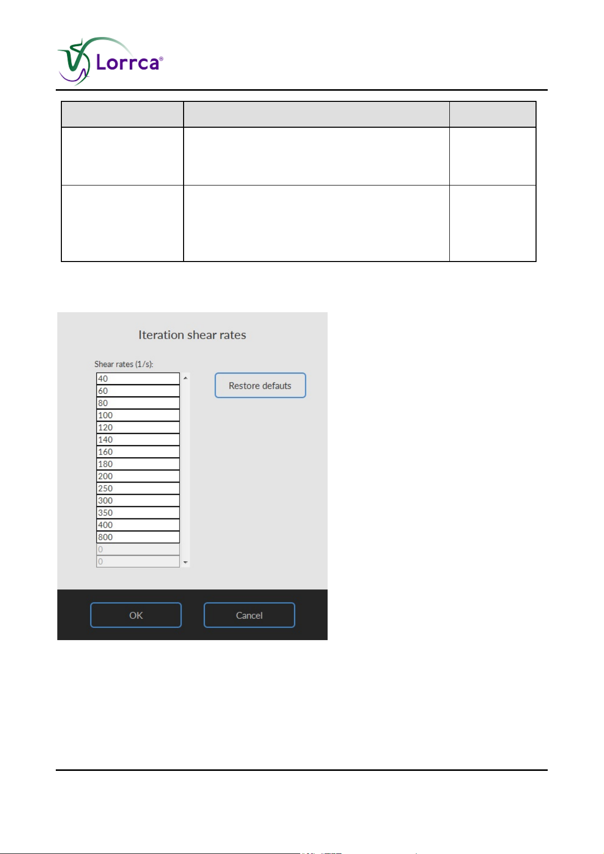
Lorrca MaxSis Program
Settings parameter Description Range
sorting the measurement points, and if intermediate
disaggregation is not enabled, it is possible to study
memory effects (hysteresis) of RBC aggregation vs.
shear rate.
Iteration shear rates
Presets values to which the iteration procedure is
performed. Default values are applicable for human
RBC’s.
Press <E
DIT> to change the values.
6.4.4.3.1. Edit Iteration shear rates
[1, 7745] 1/s
Lorrca Maxsis User Manual Page 65
Version 5.04 MRN-231-EN
Page 68

Lorrca MaxSis Program
6.4.4.4. FSAR options
Settings parameter Description Range
Perform FSAR
procedure
Checkbox, to include the FSAR procedure in the
aggregation measurement. The FSAR
-
measurement is performed immediately following
the iteration procedure. Note: The acquisition of the
backscatter intensity during the FSAR measurement
is similar to that during the iteration procedure (one
sample per cup revolution). Acquisition parameters
of the iteration procedure (Samples per shear rate,
Maximum deviation, Iteration timeout) also apply to
the FSAR measurement.
Low shear rate (1/s) Low shear rate for determining FSARIscglow/I0. The
[1, 2500] /s
low shear rate is taken 10/s by default.
6.4.5. Osmoscan options
This is only available when “Enable Osmoscan” is checked, and Osmoscan option is available on
the instrument
Settings parameter Description Range
Enable Osmoscan Checkbox, Turns this option on/off
-
Osmoscan shear
…
stress (Pa)
Step size (mOsm/kg) …
Pump speed (ml/s)
Total scan time (s) …
Total consumption (ml) …
Calc. area between: Checkbox, Min or
…and (mOsm/kg)
[30, 30] (Pa)
[5, 5]
(mOsm/kg)
[0.0053,0.0]
(ml/s)
540 (s)
(ml)
[75,75]
[450,450]
Page 66 Lorrca Maxsis User Manual
Version 5.04 MRN-231-EN
Page 69

Lorrca MaxSis Program
6.4.6. Oxygenscan options
This is only available when “Enable pO2 scan” is checked, and Oxygen scan module is available
on the instrument
Settings parameter Description Range
Enable pO2 axis Checkbox, Turns this option on/off
Logarithmic pO2 axis Checkbox
pO2 scan shear stress
(PA)
Determine pO2 every
(s)
Moving average size
Calc area between:
...and (mmHg)
Scan steps see pO2 Steps (on page 68)
pO2 control Checkbox
0-100
0-3600
0-40
0-250
0-250
pO2 control max.
speed (mmHg/min)
(visible when pO2 control is activated) For adjusting
deoxygenation
pO2 control P-term (visible when pO2 control is activated) For adjusting
deoxygenation
pO2 control I-term (visible when pO2 control is activated) For adjusting
deoxygenation
Lorrca Maxsis User Manual Page 67
Version 5.04 MRN-231-EN
Page 70
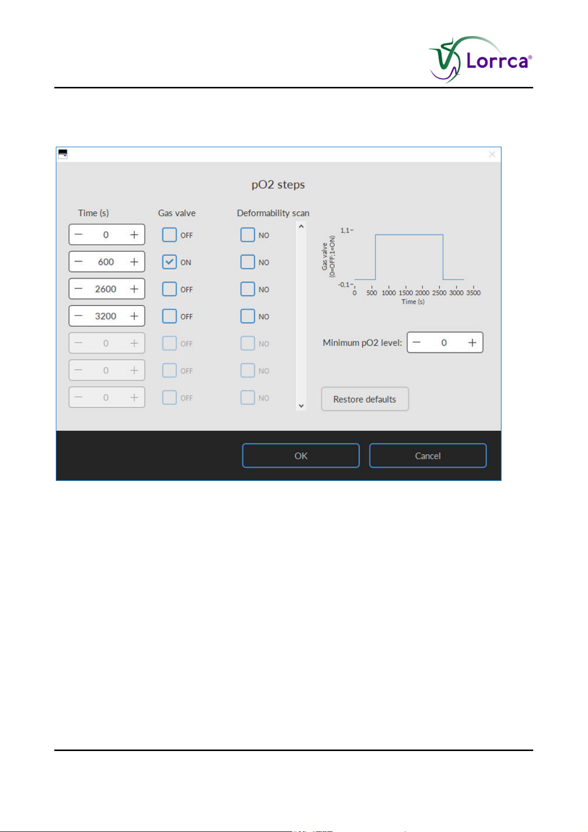
Lorrca MaxSis Program
6.4.6.1. pO2 Steps
If pO2 control is disabled:
Page 68 Lorrca Maxsis User Manual
Version 5.04 MRN-231-EN
Page 71
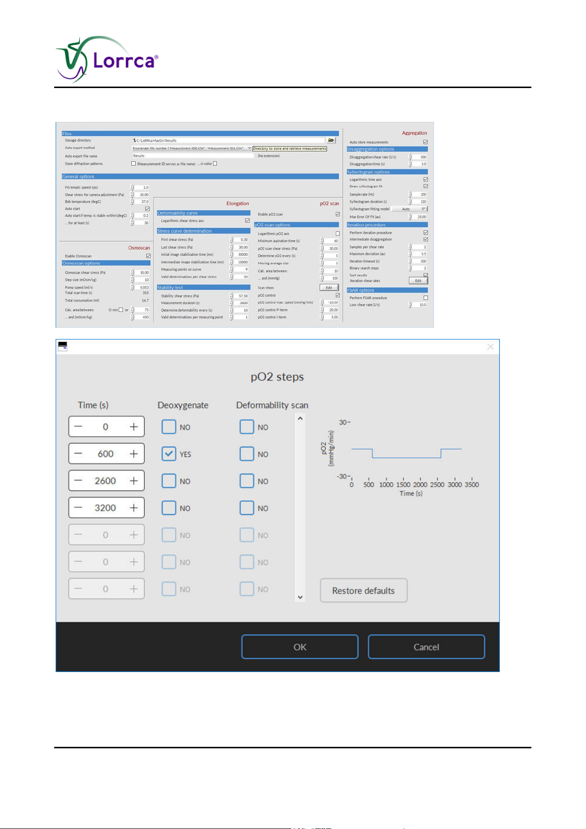
Lorrca MaxSis Program
If pO2 control is enabled:
Lorrca Maxsis User Manual Page 69
Version 5.04 MRN-231-EN
Page 72
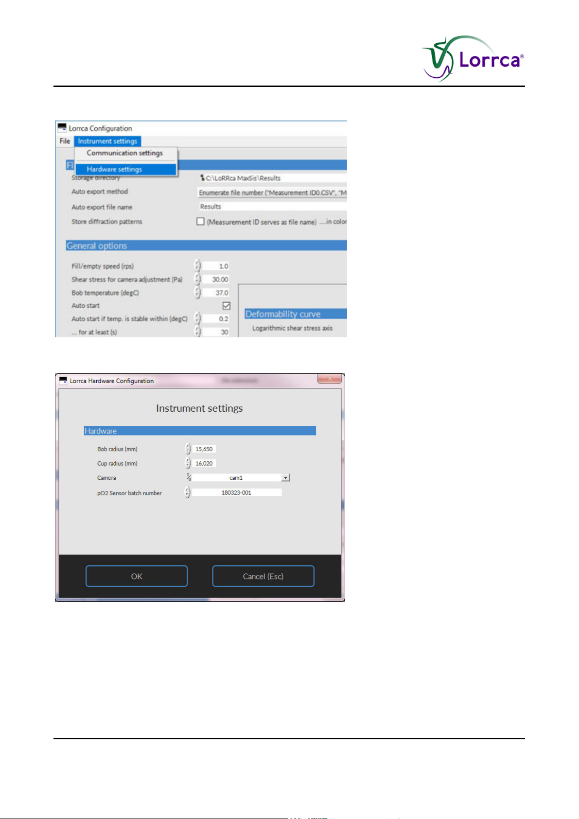
Lorrca MaxSis Program
Select HARDWARE SETTINGS at the top of the SETTINGS-screen:
Screen Instrument settings appears:
Page 70 Lorrca Maxsis User Manual
Version 5.04 MRN-231-EN
Page 73
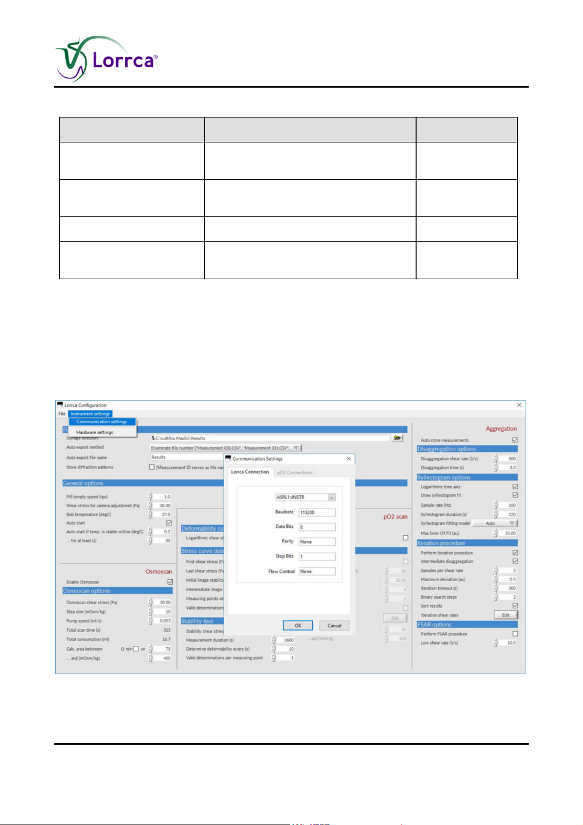
Lorrca MaxSis Program
Settings parameter Description Range/Setting
BOB radius (mm) Outer radius of the static bob, in
[5, 50] mm
millimeters.
CUP radius (mm) Inner radius of the rotating cup, in
millimeters.
Camera
pO2 Sensor batch number
(used for pO2 option)
File name for calibration information
sensor-spot
6.4.7. Screen communication settings
[5, 50] mm
cam1
XXXXXX-xxx
Lorrca Maxsis User Manual Page 71
Version 5.04 MRN-231-EN
Page 74
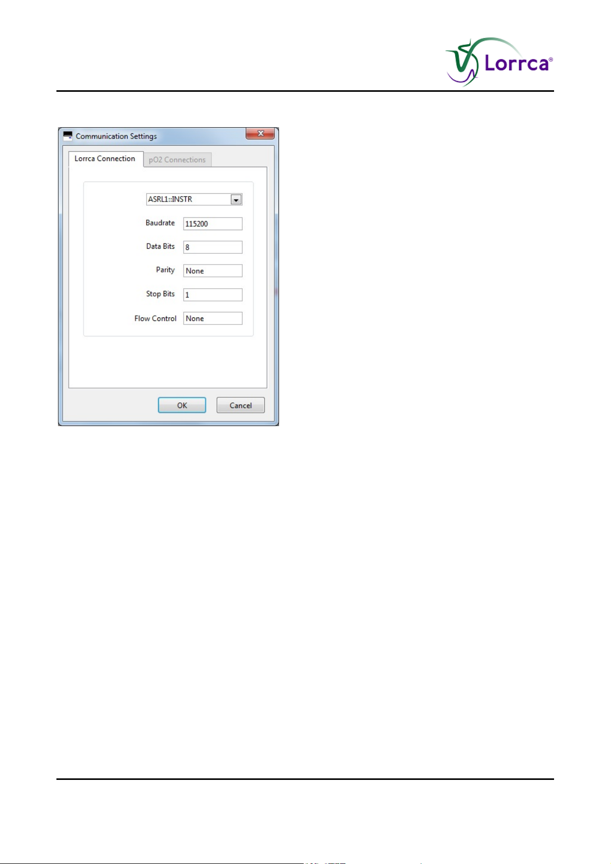
Lorrca MaxSis Program
OMMUNICATION SETTINGS: Select the output port for communication.
C
Lorrca Connection
1. Serial output comport.ASRL1::INSTR. By default
2. Baud rate. Selectable 1200, 4800 ,9600, 38400 and many more default is set on 115200
3. Data bits. Selectable 7 or 8 data bits
4. Party bit: Selectable none, space, mark, even and odd
5. Stop bits: Selectable 1, 1.5 or 2 stop bits
6. Flow control: Selectable for;
None
XON/XOFF
RTS/CTS
DTR/DSR
XON/XOFF & RTS/CTS
XON/XOFF & DTR/DSR
Page 72 Lorrca Maxsis User Manual
Version 5.04 MRN-231-EN
Page 75
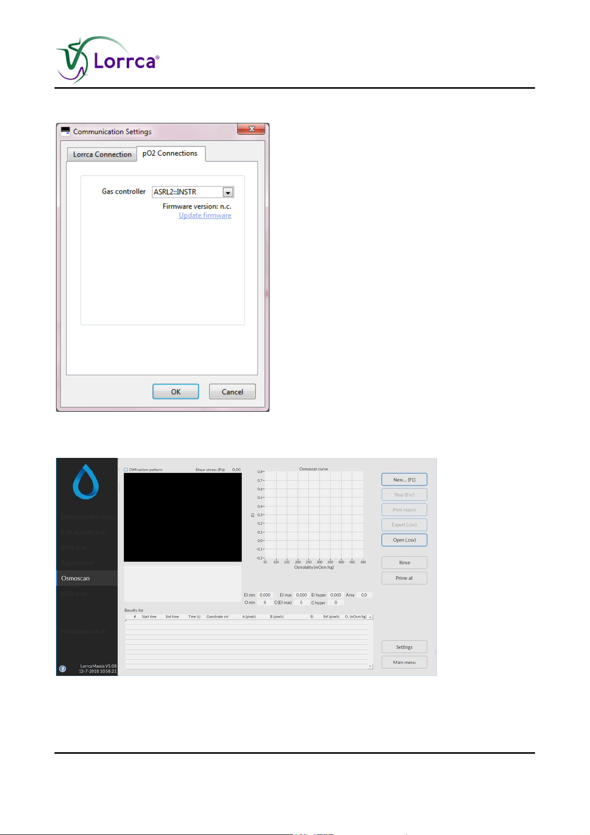
pO2 Connection
Lorrca MaxSis Program
6.5. Osmoscan screen
Lorrca Maxsis User Manual Page 73
Version 5.04 MRN-231-EN
Page 76
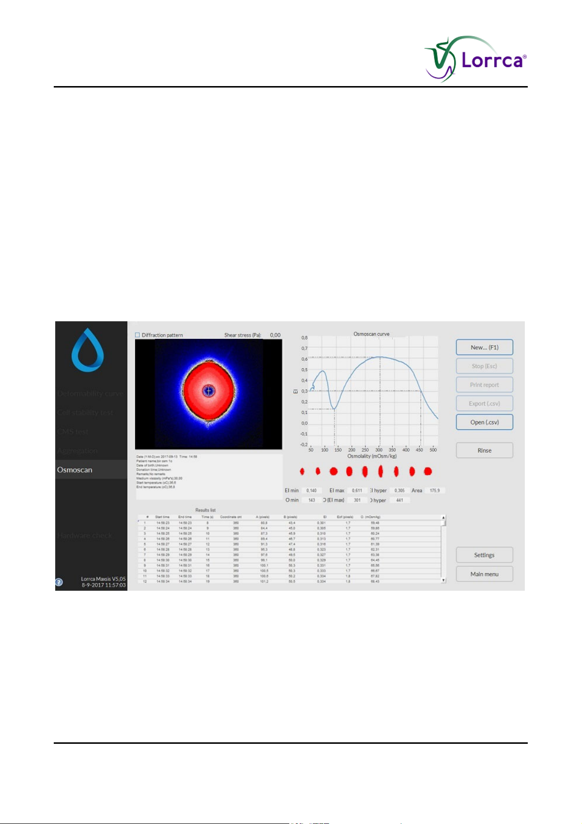
Lorrca MaxSis Program
This screen appears when starting a scan. See Osmoscan options (on page 66) settings for
details on the Settings parameters that influence the measurement.
A measurement starts after subsequently clicking <N
On this screen are shown:
1. Coloured diffraction pattern.
2. Curve display screen.
3. Indication of cell shape.
4. Measurement and sample details.
5. Measurement results.
6. Parameters.
6.5.1. Osmoscan result screen
EW...(F1)>.
At measurement completion measurement results are displayed on-screen, the software offers an
option to print (yes/no).
It is possible to print a measurement report by clicking the <P
RINT REPORT> button.
The latest results automatically overwrite the results file (Default name: Results.CSV). If enabled,
the results will also be written to other files (see “Settings/Files (on page 59)”). Return to the main
menu by clicking the <M
AIN MENU> button.
Check Osmoscan parameters explanation (on page 75)
Page 74 Lorrca Maxsis User Manual
Version 5.04 MRN-231-EN
Page 77

Lorrca MaxSis Program
6.5.1.1. Osmoscan parameters explanation
The following result parameters are given in Results file and printed report:
Parameter Description
# Measurement number
Start time Actual time that was valid after setting a new shear stress and
immediately following the image stabilisation time.
End time Actual time that was valid after the last EI measurement at the given
shear stress was performed.
Time (s) Time, in seconds, since the beginning of the measurement.
Coordinate count Number of coordinates in the iso-intensity curve that describes the
shape of the diffraction pattern.
A (pixels) Vertical axis of ellipse.
B (pixels) Horizontal axis of ellipse.
EI Elongation index
Eof (pixels) Error of fit This parameter represents the average distance (in pixel
units) of the iso-intensity pixels to the best-fit ellipse that resulted. It
reflects how well the iso-intensity coordinates comply with the ellipse
model.
O, (mOsm/kg) Osmolality is a count of the number of particles in a fluid sample,
mOsm/kg means milli-osmole per kilogram
Lorrca Maxsis User Manual Page 75
Version 5.04 MRN-231-EN
Page 78
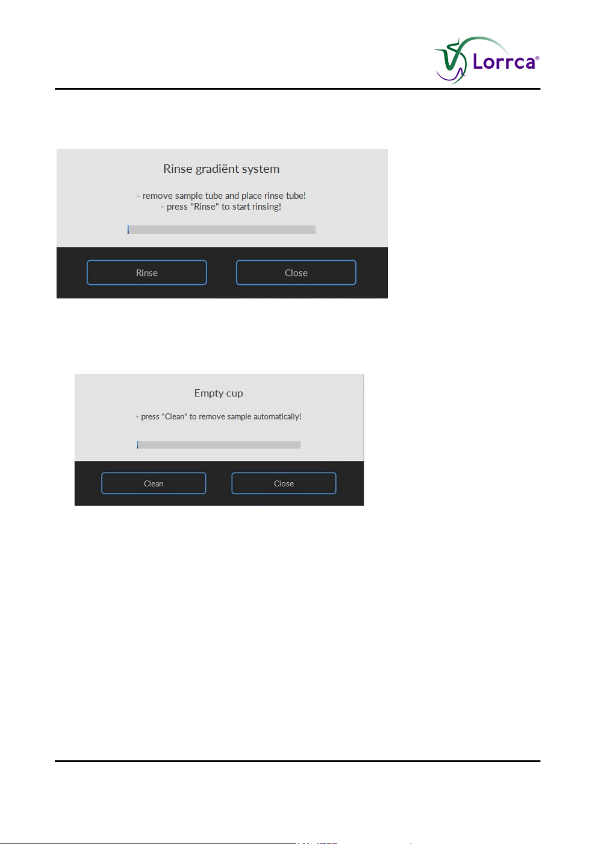
Lorrca MaxSis Program
6.5.1.2. Rinse gradiënt Osmoscan screen
Screen R
INSE GRADIENT SYSTEM appears:
1. Open the hood.
2. Remove empty sample tube.
3. Place tube with demi-water (+/- 2,5 ml).
4. Press <R
Screen E
INSE>. to remove sample and rinse the system. Sample is lost and no longer available.
MPTY CUP appears.
Press <C
LEAN>
5. Remove empty (rinse) tube.
6. Press OK and the Osmoscan screen appears.
7. Press <F1> or click on N
EW...F1 to perform another Osmoscan.
or
Press <
MAIN MENU> to perform other tests (perform in that case also an “END OF DAY WASH (on page
142)”).
or
Exit the software and perform an “E
ND OF DAY WASH (on page 142)”.
Page 76 Lorrca Maxsis User Manual
Version 5.04 MRN-231-EN
Page 79
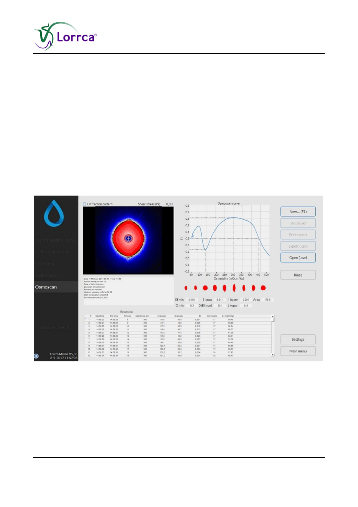
Lorrca MaxSis Program
6.5.2. Osmoscan curve
The Osmoscan window appears by clicking the <Osmoscan>-button from the introduction window.
A measurement starts after clicking "N
starting a scan. See "Settings" for details on the Settings parameters that influence the
measurement.
EW…(F1)". The figure shows the window that appears before
A measurement starts after subsequently clicking <N
On this screen are shown:
1. Coloured diffraction pattern.
2. Curve display screen.
3. Indication of cell shape.
4. Measurement and sample details.
5. Measurement results.
6. Parameters
EW...(F1)>.
Lorrca Maxsis User Manual Page 77
Version 5.04 MRN-231-EN
Page 80
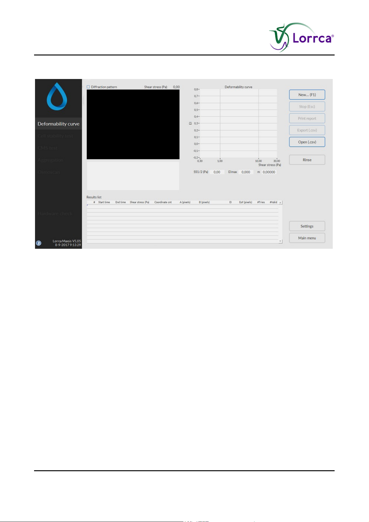
Lorrca MaxSis Program
6.6. Deformability curve determination screen
This screen appears when starting a deformability measurement. See Deformability curve (on
page 60) for details on the Settings parameters that influence the measurement.
A measurement starts after subsequently clicking <N
EW...(F1)>.
On this screen are shown:
1. Coloured diffraction pattern.
2. Curve display screen.
3. Indication of cell shape.
4. Measurement and sample details.
5. Measurement results.
Page 78 Lorrca Maxsis User Manual
Version 5.04 MRN-231-EN
Page 81
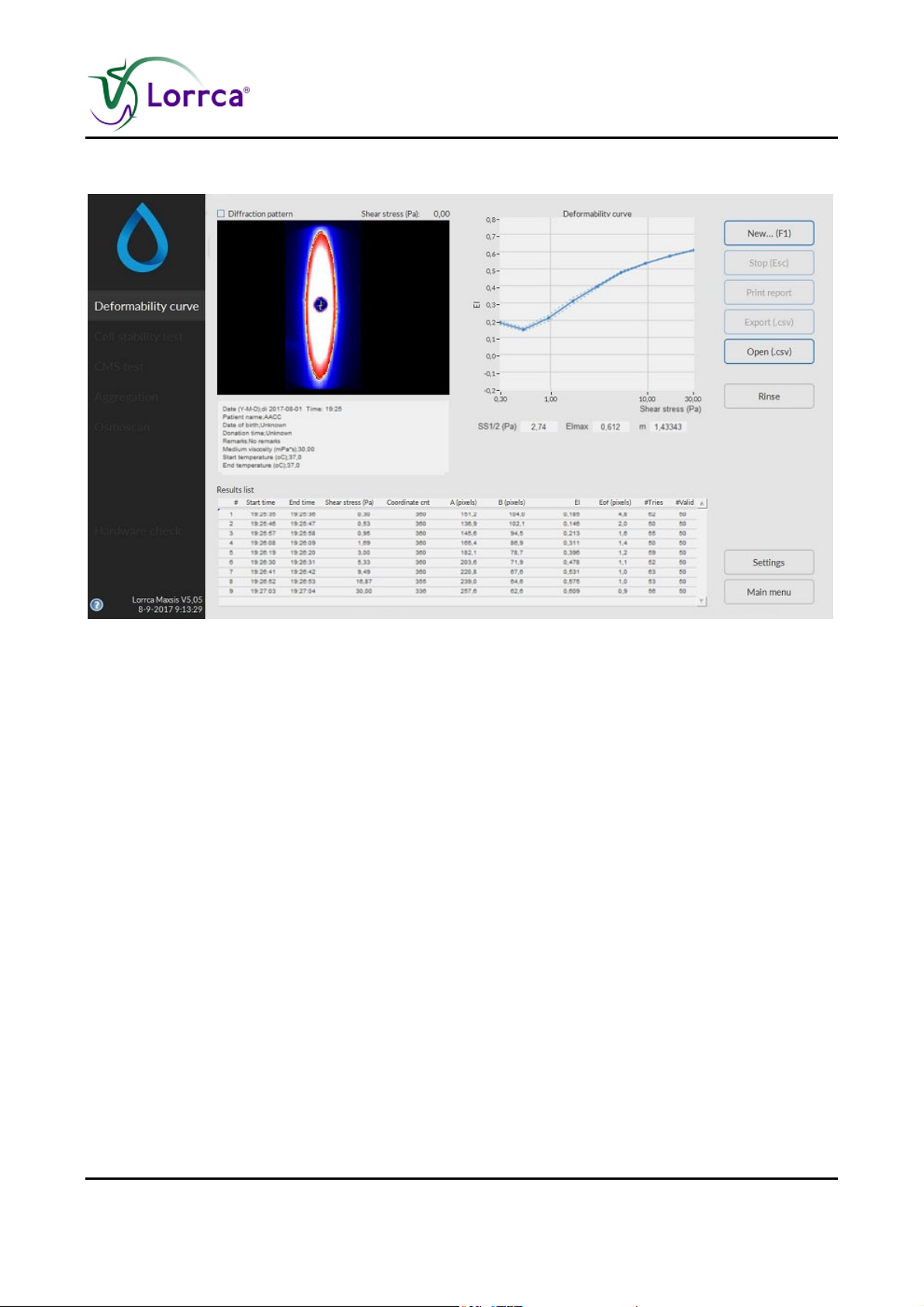
Lorrca MaxSis Program
6.6.1. Deformability curve result screen
At measurement completion measurement results are displayed on-screen, the software offers an
option to print (yes/no).
It is possible to print a measurement report by clicking the <P
RINT REPORT> button.
The latest results automatically overwrite the results file (Default name: Results.CSV). If enabled,
the results will also be written to other files (see “Settings/Files (on page 59)”). Return to the main
menu by clicking the <M
AIN MENU> button.
Check Deformability curve determination parameters explanation (on page 80)
Lorrca Maxsis User Manual Page 79
Version 5.04 MRN-231-EN
Page 82

Lorrca MaxSis Program
6.6.1.1. Deformability curve determination parameters explanation
The following result parameters are given in Results file and printed report:
Parameter Description
Start time Actual time that was valid after setting a new shear stress and
immediately following the image stabilisation time.
End time Actual time that was valid after the last EI measurement at the given
shear stress was performed.
Shear stress (Pa) Applied shear stress.
Coordinate count or
Crd cnt
Number of coordinates in the iso-intensity curve that describes the
shape of the diffraction pattern.
A (pixels) Vertical axis of ellipse.
B (pixels) Horizontal axis of ellipse.
EI Elongation index.
Eof (pixels) Error of fit. This parameter represents the average distance (in pixel
units) of the iso-intensity pixels to the best-fit ellipse that resulted. It
reflects how well the iso-intensity coordinates comply with the ellipse
model.
#Tries Number of diffraction patterns that were analysed at the current shear
stress.
#Valid The number of diffraction patterns that were within the ±2SD
confidence interval. This number agrees with the desired count as
given in the Settings menu (<Settings<Determinations per shear
stress).
6.6.1.2. Explain Rinse cup deformability screen
Page 80 Lorrca Maxsis User Manual
Version 5.04 MRN-231-EN
Page 83
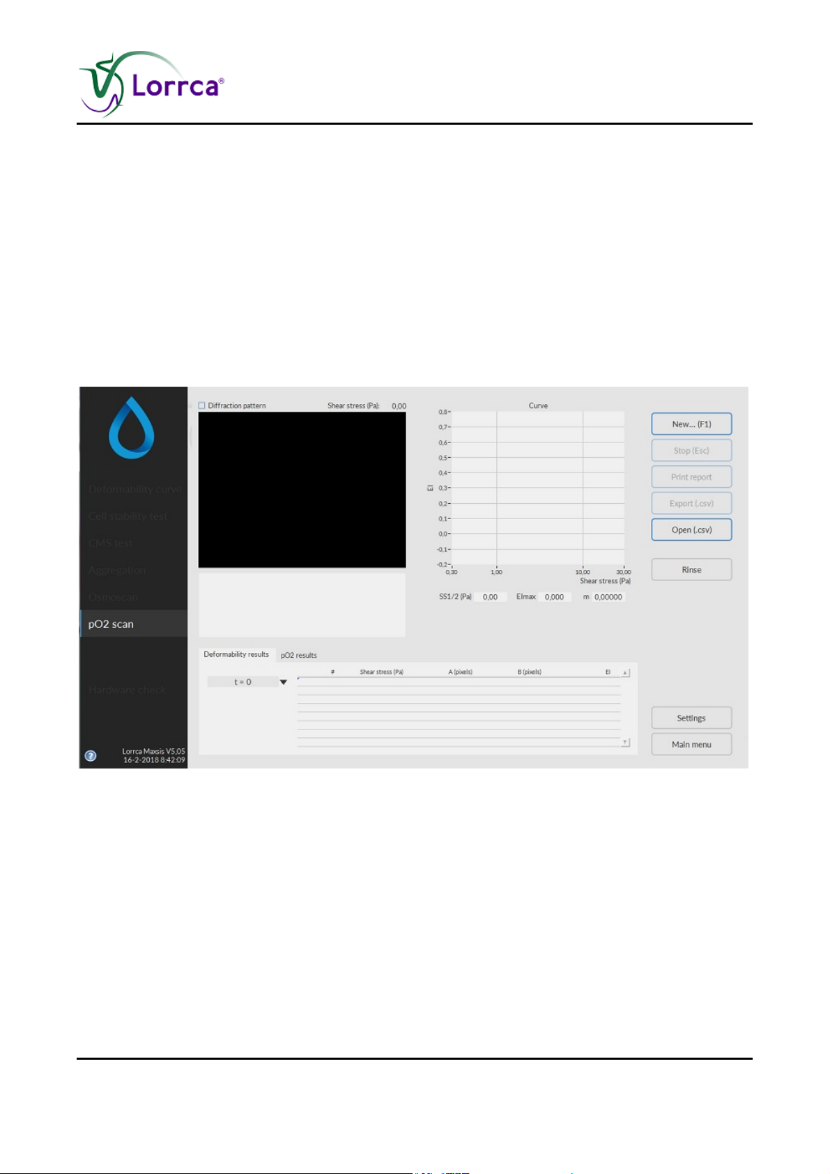
Lorrca MaxSis Program
After a measurement has completed, the program sets the fill/empty speed (<SETTINGS> <GENERAL
OPTIONS
FILL/EMPTY SPEED (RPS)>) and asks the operator to remove the blood sample.
Press <CLEAN>.
Sample is removed and system is rinsed. Sample is lost and no longer available.
A new measurement can now be started or return to the main menu by pressing <M
perform other tests.
Or exit the software and perform an “E
ND OF DAY WASH (on page 142)”.
6.7. Oxygenscan screen
AIN MENU> to
This screen appears when starting a scan. See Oxyscan options (on page 67) settings for details
on the Settings parameters that influence the measurement.
A measurement starts after subsequently clicking <N
EW...(F1)>.
On this screen are shown:
1. Coloured diffraction pattern.
2. Curve display screen.
3. Indication of cell shape.
4. Measurement and sample details.
5. Measurement results.
6. Parameters.
Lorrca Maxsis User Manual Page 81
Version 5.04 MRN-231-EN
Page 84
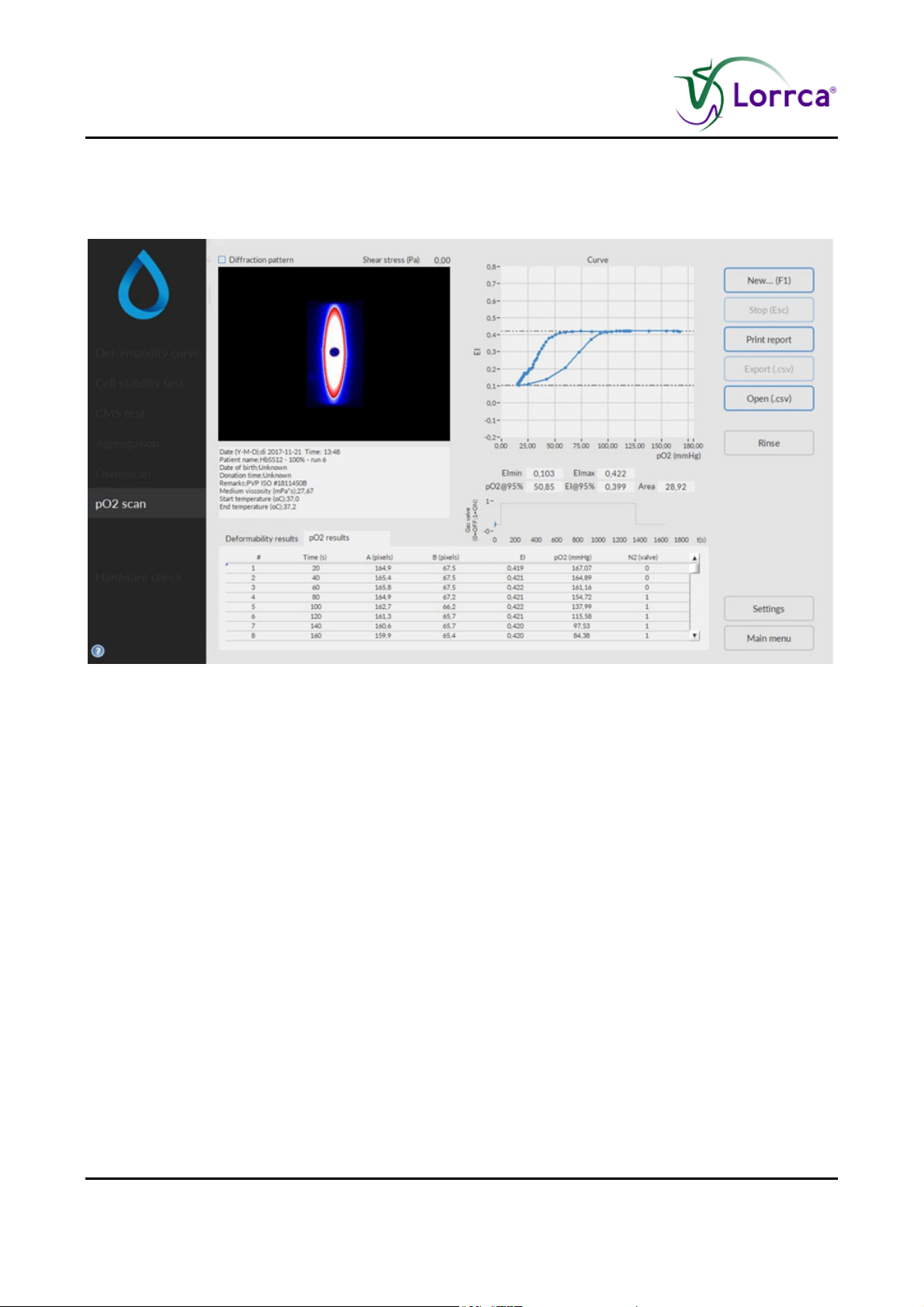
Lorrca MaxSis Program
6.7.1. Oxygenscan result screen
At measurement completion measurement results are displayed on-screen, the software offers an
option to print (yes/no).
It is possible to print a measurement report by clicking the <P
RINT REPORT> button.
The latest results automatically overwrite the results file (Default name: Results.CSV). If enabled,
the results will also be written to other files (see “Settings/Files (on page 59)”). Return to the main
menu by clicking the <M
AIN MENU> button.
Check Oxygenscan parameters explanation (on page 83)
Page 82 Lorrca Maxsis User Manual
Version 5.04 MRN-231-EN
Page 85

Lorrca MaxSis Program
6.7.1.1. Oxygenscan parameters explanation
The following result parameters are given in Results file and printed report:
Parameter Description
# Measurement number
Start time Actual time that was valid after setting a new shear stress and
immediately following the image stabilisation time.
End time Actual time that was valid after the last EI measurement at the given
shear stress was performed.
Time (s) Time, in seconds, since the beginning of the measurement.
Coordinate count Number of coordinates in the iso-intensity curve that describes the
shape of the diffraction pattern.
A (pixels) Vertical axis of ellipse.
B (pixels) Horizontal axis of ellipse.
EI Elongation index
P02 (mm/Hg)
N2 (valve)
6.7.1.2. Explain Rinse gradient Oxygen screen
Screen R
INSE GRADIENT SYSTEM appears:
1. Open the hood.
2. Remove empty sample tube.
3. Place tube with demi-water (+/- 2,5 ml).
Lorrca Maxsis User Manual Page 83
Version 5.04 MRN-231-EN
Page 86

Lorrca MaxSis Program
4. Press <RINSE>. to remove sample and rinse the system. Sample is lost and no longer available.
Screen E
MPTY CUP appears.
Press <C
LEAN>
5. Remove empty (rinse) tube.
6. Press OK and the Oxygenscan screen appears.
7. Press <F1> or click on N
EW...F1 to perform another Oxygenscan.
or
Press <
MAIN MENU> to perform other tests (perform in that case also an “END OF DAY WASH (on page
142)”).
or
Exit the software and perform an “E
ND OF DAY WASH (on page 142)”.
Page 84 Lorrca Maxsis User Manual
Version 5.04 MRN-231-EN
Page 87
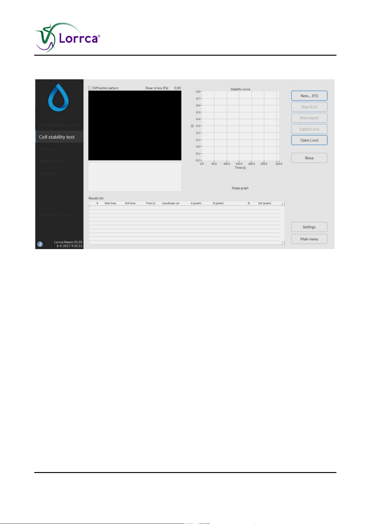
Lorrca MaxSis Program
6.8. Stability Curve determination screen
This screen appears when starting a stability test. See Stress curve determination (on page 61)
for details on the Settings parameters that influence the measurement.
A measurement starts after subsequently clicking <N
EW...(F1)>.
On this screen are shown:
1. Coloured diffraction pattern.
2. Curve display screen.
3. Indication of cell shape.
4. Measurement and sample details.
5. Measurement results.
Lorrca Maxsis User Manual Page 85
Version 5.04 MRN-231-EN
Page 88
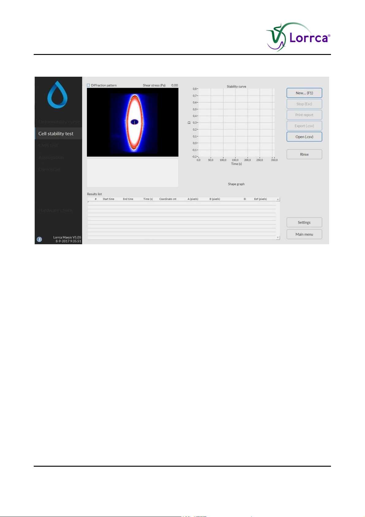
Lorrca MaxSis Program
6.8.1. Stability curve determination results screen
At measurement completion measurement results are displayed on-screen, the software offers an
option to print (yes/no).
It is possible to print a measurement report by clicking the <P
RINT REPORT> button.
The latest results automatically overwrite the results file (Default name: Results.CSV). If enabled,
the results will also be written to other files (see “Settings/Files (on page 59)”). Return to the main
menu by clicking the <M
AIN MENU> button.
Check Stability curve determination parameters explanation (on page 87)
Page 86 Lorrca Maxsis User Manual
Version 5.04 MRN-231-EN
Page 89

Lorrca MaxSis Program
6.8.1.1. Stability curve determination parameters explanation
The following result parameters are given in Results file and printed report:
Parameter Description
# Measurement number
Start time Actual time that was valid after setting a new shear stress and
immediately following the image stabilisation time.
End time Actual time that was valid after the last EI measurement at the given
shear stress was performed.
Time (s) Time, in seconds, since the beginning of the measurement.
Coordinate count Number of coordinates in the iso-intensity curve that describes the
shape of the diffraction pattern.
A (pixels) Vertical axis of ellipse.
B (pixels) Horizontal axis of ellipse.
EI Elongation index
Eof (pixels) Error of fit. This parameter represents the average distance (in pixel
units) of the iso-intensity pixels to the best-fit ellipse that resulted. It
reflects how well the iso-intensity coordinates comply with the ellipse
model.
6.8.1.2. Open Stability curve files
A .SMP or .CSV result file can be shown again. Default folder C://LoRRca
MaxSis/Results/Elongation.
Lorrca Maxsis User Manual Page 87
Version 5.04 MRN-231-EN
Page 90
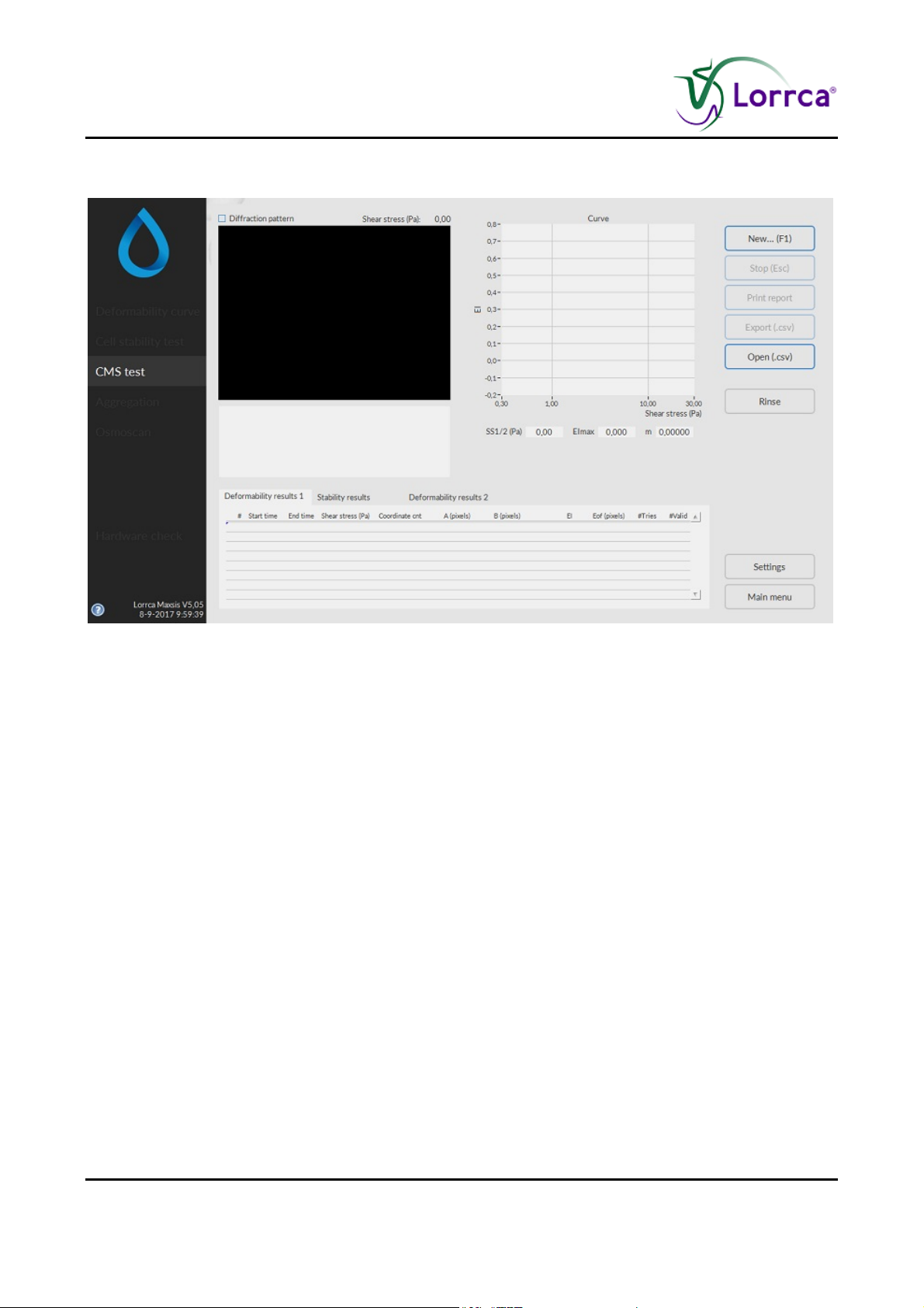
Lorrca MaxSis Program
6.9. Cell Membrane stability screen
This screen appears when starting a stability test. See Stability test (on page 62) Settings for
details on the Settings parameters that influence the measurement.
The cell membrane stability test consists of 3 stages.
A measurement starts after subsequently clicking <N
EW...(F1)>.
On this screen are shown:
1. Coloured diffraction pattern.
2. Curve display screen.
3. Indication of cell shape.
4. Measurement and sample details.
5. Measurement results.
Page 88 Lorrca Maxsis User Manual
Version 5.04 MRN-231-EN
Page 91
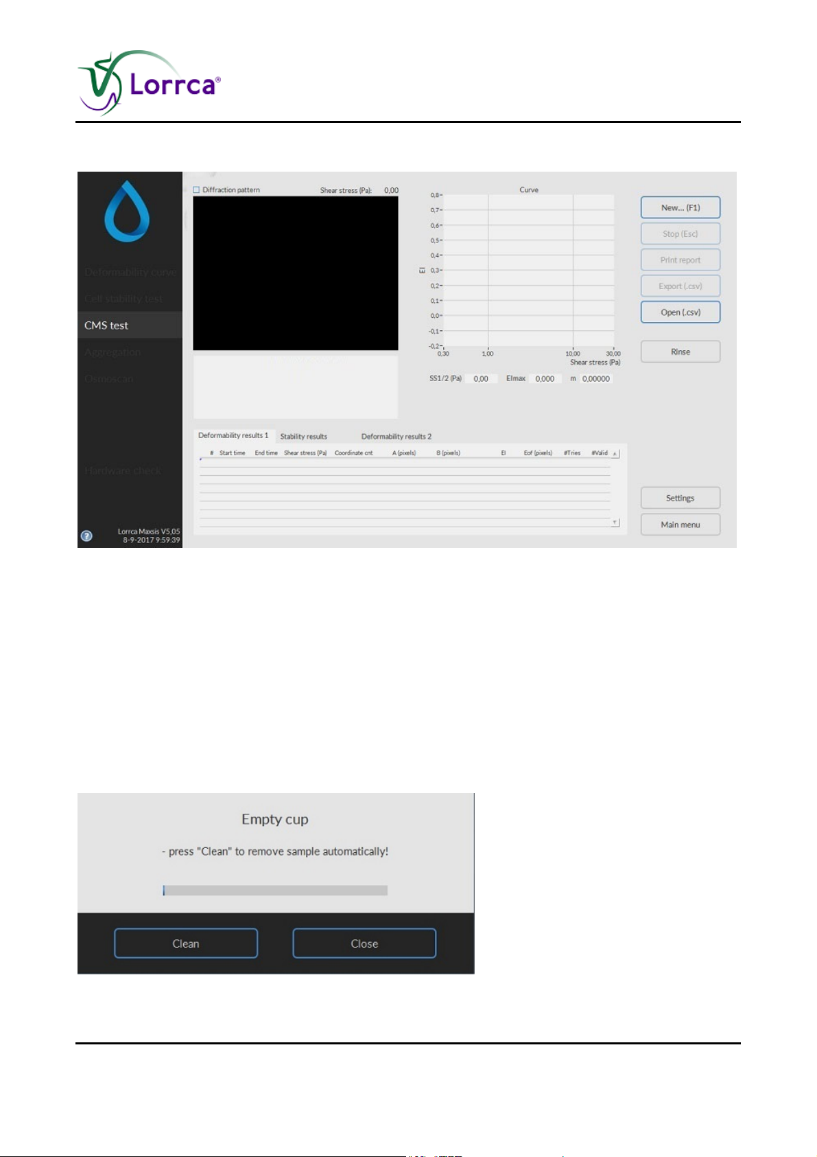
Lorrca MaxSis Program
6.9.1. Deformability results 1 screen
At measurement completion measurement results are displayed on-screen, the software offers an
option to print (yes/no).
It is possible to print a measurement report by clicking the <P
RINT REPORT> button.
The latest results automatically overwrite the results file (Default name: Results.CSV). If enabled,
the results will also be written to other files (see “Settings/Files (on page 59)”). Return to the main
menu by clicking the <M
AIN MENU> button.
Check Deformability results 1 parameters explanation (on page 93)
6.9.2. Rinse cup cell membrane screen
Lorrca Maxsis User Manual Page 89
Version 5.04 MRN-231-EN
Page 92
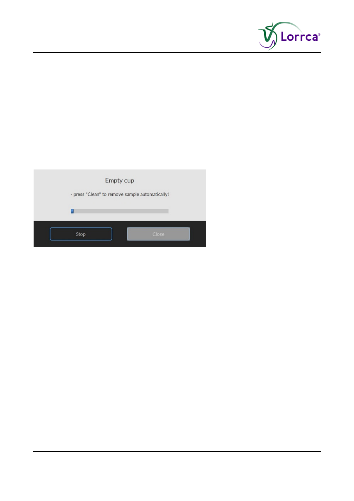
Lorrca MaxSis Program
After a measurement has completed, the program sets the fill/empty speed (<SETTINGS> <GENERAL
OPTIONS
FILL/EMPTY SPEED (RPS)>) and asks the operator to remove the blood sample.
Press <CLEAN>.
Sample is removed and system is rinsed. Sample is lost and no longer available.
A new measurement can now be started or return to the main menu by pressing <M
AIN MENU> to
perform other tests.
Or exit the software and perform an “E
ND OF DAY WASH (on page 142)”.
Return to Cell Membrane stability screen (on page 88) or Deformability results screen (on
page 89).
6.9.3. Empty cup cell membrane screen
Page 90 Lorrca Maxsis User Manual
Version 5.04 MRN-231-EN
Page 93
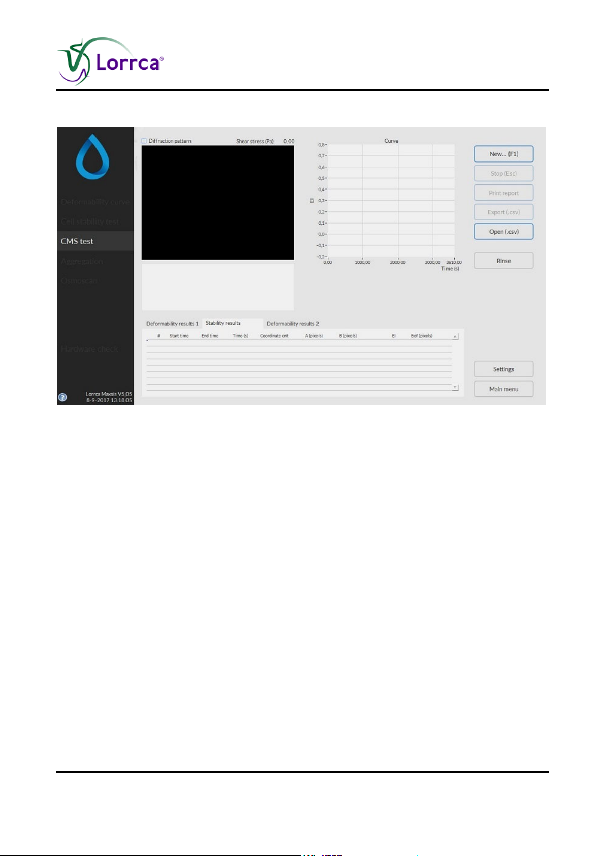
Lorrca MaxSis Program
6.9.4. Cell membrane stability results screen
At measurement completion measurement results are displayed on-screen, the software offers an
option to print (yes/no).
It is possible to print a measurement report by clicking the <P
RINT REPORT> button.
The latest results automatically overwrite the results file (Default name: Results.CSV). If enabled,
the results will also be written to other files (see “Settings/Files (on page 59)”). Return to the main
menu by clicking the <M
AIN MENU> button.
Check Stability results parameters explanation (on page 94)
Lorrca Maxsis User Manual Page 91
Version 5.04 MRN-231-EN
Page 94
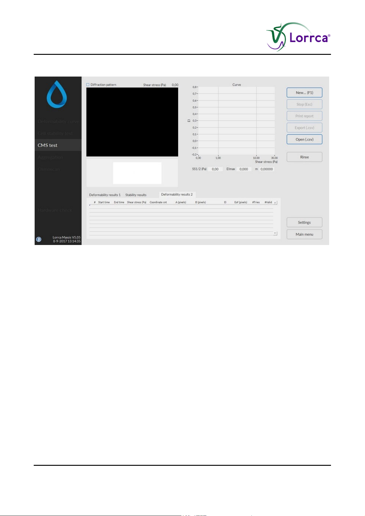
Lorrca MaxSis Program
6.9.5. Deformability results 2 screen
At measurement completion measurement results are displayed on-screen, the software offers an
option to print (yes/no).
It is possible to print a measurement report by clicking the <P
RINT REPORT> button.
The latest results automatically overwrite the results file (Default name: Results.CSV). If enabled,
the results will also be written to other files (see “Settings/Files (on page 59)”). Return to the main
menu by clicking the <M
AIN MENU> button.
Check Deformability results 2 parameters explanation (on page 95)
Page 92 Lorrca Maxsis User Manual
Version 5.04 MRN-231-EN
Page 95

Lorrca MaxSis Program
6.9.6. At measurement completion
6.9.6.1. Deformability results 1 parameters explanation
The following result parameters are given in Results file and printed report:
Parameter Description
Start time
Actual time that was valid after setting a new shear stress and
immediately following the image stabilisation time.
End time Actual time that was valid after the last EI measurement at the given
shear stress was performed.
Shear stress (Pa) Applied shear stress.
Coordinate count or
Crd cnt
Number of coordinates in the iso-intensity curve that describes the
shape of the diffraction pattern.
A (pixels) Vertical axis of ellipse.
B (pixels) Horizontal axis of ellipse.
EI Elongation index.
Eof (pixels) Error of fit. This parameter represents the average distance (in pixel
units) of the iso-intensity pixels to the best-fit ellipse that resulted. It
reflects how well the iso-intensity coordinates comply with the ellipse
model.
#Tries
Number of diffraction patterns that were analysed at the current shear
stress.
#Valid
The number of diffraction patterns that were within the ±2SD
confidence interval. This number agrees with the desired count as
given in the Settings menu (<Settings<Determinations per shear
stress).
Return to Cell Membrane stability screen (on page 88) or Deformability results screen (on
page 89).
Lorrca Maxsis User Manual Page 93
Version 5.04 MRN-231-EN
Page 96

Lorrca MaxSis Program
6.9.6.2. Stability results parameters explanation
The following result parameters are given in Results file and printed report:
Parameter Description
# Measurement number
Start time Actual time that was valid after setting a new shear stress and
immediately following the image stabilisation time.
End time Actual time that was valid after the last EI measurement at the given
shear stress was performed.
Time (s) Time, in seconds, since the beginning of the measurement.
Coordinate count Number of coordinates in the iso-intensity curve that describes the
shape of the diffraction pattern.
A (pixels) Vertical axis of ellipse.
B (pixels) Horizontal axis of ellipse.
EI Elongation index
Eof (pixels) Error of fit. This parameter represents the average distance (in pixel
units) of the iso-intensity pixels to the best-fit ellipse that resulted. It
reflects how well the iso-intensity coordinates comply with the ellipse
model.
Return to Cell Membrane stability screen (on page 88) or Deformability results screen (on
page 89).
Page 94 Lorrca Maxsis User Manual
Version 5.04 MRN-231-EN
Page 97

Lorrca MaxSis Program
6.9.6.3. Deformability results 2 parameters explanation
The following result parameters are given in Results file and printed report:
Parameter Description
Start time Actual time that was valid after setting a new shear stress and
immediately following the image stabilisation time.
End time Actual time that was valid after the last EI measurement at the given
shear stress was performed.
Shear stress (Pa) Applied shear stress.
Coordinate count or
Crd cnt
Number of coordinates in the iso-intensity curve that describes the
shape of the diffraction pattern.
A (pixels) Vertical axis of ellipse.
B (pixels) Horizontal axis of ellipse.
EI Elongation index.
Eof (pixels) Error of fit. This parameter represents the average distance (in pixel
units) of the iso-intensity pixels to the best-fit ellipse that resulted. It
reflects how well the iso-intensity coordinates comply with the ellipse
model.
#Tries Number of diffraction patterns that were analysed at the current shear
stress.
#Valid The number of diffraction patterns that were within the ±2SD
confidence interval. This number agrees with the desired count as
given in the Settings menu (<Settings<Determinations per shear
stress).
Lorrca Maxsis User Manual Page 95
Version 5.04 MRN-231-EN
Page 98
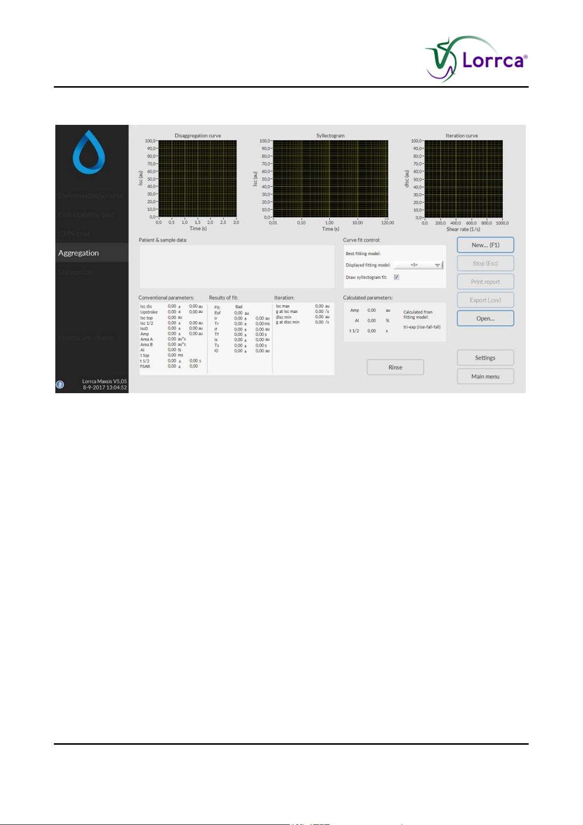
Lorrca MaxSis Program
6.10. RBC aggregation screen
This screen appears when starting RBC aggregation test. See Aggregation (on page 62) settings
and the following option selections for details on the Settings parameters that influence the
measurement.
1. Disaggregation level.
2. Syllectogram, following cup cessation.
3. Iteration curve (I()) retrieving the threshold shear rate.
4. Results area.
5. Syllectogram model selection, control for displaying the curve fit and an indication of the bestfitting model
Page 96 Lorrca Maxsis User Manual
Version 5.04 MRN-231-EN
Page 99
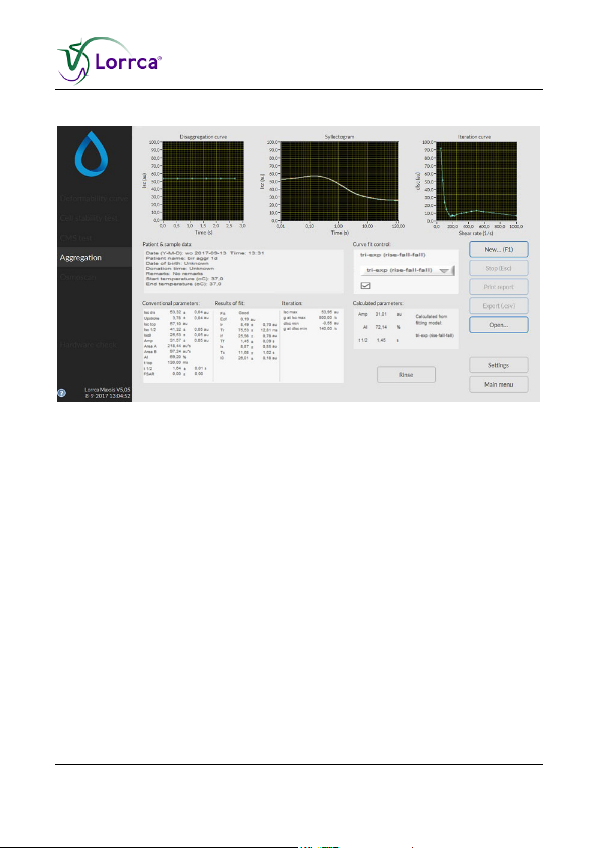
Lorrca MaxSis Program
6.10.1. RBC aggregation result screen
At measurement completion measurement results are displayed on-screen, the software offers an
option to print (yes/no).
It is possible to print a measurement report by clicking the <P
RINT REPORT> button.
The latest results automatically overwrite the results file (Default name: Results.CSV). If enabled,
the results will also be written to other files (see “Settings/Files (on page 59)”). Return to the main
menu by clicking the <M
AIN MENU> button.
Check RBC parameters explanation (on page 98)
Lorrca Maxsis User Manual Page 97
Version 5.04 MRN-231-EN
Page 100

Lorrca MaxSis Program
6.10.1.1. Aggregation parameters explanation
The following result parameters are given in Results file and printed report:
Result parameter Description
Patient and sample data Contains patient and sample data:
Patient name, Blood donation time, Remarks, Date and
time, Sample start/end temperature.
Conventional parameters
Iscdis Average back-scatter intensity measured during
disaggregation (prior to syllectogram measurement)
Upstroke Change in back-scatter intensity due to RBC relaxation.
Isctop – Isc dis
Isc top Maximum back-scatter intensity recorded throughout
the syllectogram => Peak intensity (usually the top of
the syllectogram).
Isc½ Back-scatter intensity at t ½
(Isc½ = Isc top – (Amp/2)).
Isc0 Syllectogram base level (average of last 40 samples).
Note that the syllectogram duration must be long
enough to obtain a valid base level, i.e., at full
aggregation.
Amp Syllectogram amplitude (Isc top – Isc0) representing the
extent of aggregation.
Area A, Area B, AI See Appendix E.
t top Time at which the peak occurs within the syllectogram
(cup cessation is taken as t=0).
t ½ Time that elapses until the peak intensity is reduced by
half the amplitude (hence, at Isc ½).
FSAR Flow to Stasis Aggregation Ratio See Appendix E
Results of fit These results correspond to the selected syllectogram
fitting model.
Fit Indicates whether the fit was successful (Good) or not
(Bad). The fit is considered "Bad" if the Eof exceeds the
Page 98 Lorrca Maxsis User Manual
Version 5.04 MRN-231-EN
 Loading...