

Page 1
17" COLOR LCD DUAL QUAD
SECURITY SURVEILLANCE SYSTEM
WITH INTERNET REMOTE VIEWING
Instruction Manual
English Version 1.0
MODEL:
SG17L7584
Copyright (c) 2006 LOREX Technology Inc.
www.lorexcctv.com
Page 2
Thank you for purchasing the IP enabled 17” LCD 2 Page/8 Channel Color Quad Observation system.
Lorex is committed to providing our customers with a high quality, reliable security product.
The IP enabled Observation system allows you to make an ethernet LAN connection from the monitor
to a router for internet monitoring. With this 2 Page Quad system, you are capable of viewing up to 8
camera locations in real time (4 cameras per page). This system provides multiple viewing options including: Quad, Sequential, Selectable or Sequential Picture in Picture, Zoom, Freeze and full screen
viewing options.
This system includes 4 Color CCD cameras and Web Ready Software to connect the monitor to a home
network. Connect a DVR or a time lapse VCR to this system to record key events. Additional cameras
can be added to view up to 8 locations.
To learn more about this 17” 2 Page/8 Channel Color Quad Observation system and to learn about our
complete range of accessory products, please visit our website at:
http://www.lorexcctv.com
CAUTION
RISK OF ELECTRIC SHOCK
DO NOT OPEN
CAUTION: TO REDUCE THE RISK OF ELECTRIC SHOCK
DO NOT REMOVE COVER (OR BACK).
NO USER SERVICEABLE PARTS INSIDE.
REFER SERVICING TO A QUALIFIED SERVICE PERSONNEL
The lightning flash with arrowhead symbol, within an
equilateral triangle, is intended to alert the user to the
presence of uninsulated “dangerous voltage” within the
product’s enclosure that may be of sufficient magnitude
to constitute a risk of electric shock to persons.
The exclamation point within an equilateral triangle is
intended to alert the user to the presence of important
operating and maintenance (servicing) instructions in
the literature accompanying the appliance.
WARNING: TO PREVENT FIRE OR SHOCK HAZARD,
DO NOT EXPOSE THIS UNIT TO RAIN OR MOISTURE.
CAUTION: TO PREVENT ELECTRIC SHOCK, MATCH WIDE BLADE
OF PLUG TO WIDE SLOT, FULLY INSERT.
2
Page 3
Important Safeguards
Important Safeguards
In addition to the careful attention devoted to quality standards in the manufacture process of your video
product, safety is a major factor in the design of every instrument. However, safety is your responsibility too.
This sheet lists important information that will help to assure your enjoyment and proper use of the video
product and accessory equipment. Please read them carefully before operating and using your video product.
Installation
1. Read and Follow Instructions - All the safety and
operating instructions should be read before the
video product is operated. Follow all operating
instructions.
2. Retain Instructions - The safety and operating
instructions should be retained for future reference.
3. Heed Warnings - Comply with all warnings on the
video product and in the operating instructions.
4. Polarization - Do not defeat the safety purpose of
the polarized or grounding-type plug.
A polarized plug has two blades with
one wider than the other.
A grounding type plug has two blades
and a third grounding prong.
The wide blade or the third prong are
provided for your safety.
If the provided plug does not fit into
your outlet, consult an electrician for
replacement of the obsolete outlet
5. .Power Sources - This video product should be
operated only from the type of power source
indicated on the marking label. If you are not sure of
the type of power supply to your location, consult
your video dealer or local power company. For video
products intended to operate from battery power, or
other sources, refer to the operating instructions.
6. Overloading - Do not overload wall outlets of
extension cords as this can result in the risk of fire
or electric shock. Overloaded AC outlets, extension
cords, frayed power cords, damaged or cracked wire
insulation, and broken plugs are dangerous. They
may result in a shock or fire hazard. Periodically
examine the cord, and if its appearance indicates
damage or deteriorated insulation, have it replaced
by your service technician.
7. Power-Cord Protection - Power supply cords should
be routed so that they are not likely to be walked on
or pinched by items placed upon or against them,
paying particular attention to cords at plugs,
convenience receptacles, and the point where they
exit from the video product.
8. Ventilation - Slots and openings in the case are
provided for ventilation to ensure reliable operation
of the video product and to protect it from
overheating. These openings must not be blocked
or covered. The openings should never be blocked
by placing the video equipment on a bed, sofa, rug,
or other similar surface. This video product should
never be placed near or over a radiator or heat
register. This video product should not be placed in
a built-in installation such as a bookcase or rack
unless proper ventilation is provided or the video
product manufacturer’s instructions have been
followed.
9. Attachments - Do not use attachments unless
recommended by the video product manufacturer as
they may cause a hazard.
10. Water and Moisture - Do not use this video product
near water. For example, near a bath tub, wash bowl,
kitchen sink or laundry tub, in a wet basement, near
a swimming pool and the like.
Caution: Maintain electrical safety. Powerline
operated equipment or accessories connected to
this unit should bear the UL listing mark of CSA
certification mark on the accessory itself and should
not be modified so as to defeat the safety features.
This will help avoid any potential hazard from
electrical shock or fire. If in doubt, contact qualified
service personnel.
11. Accessories - Do not place this video equipment
on an unstable cart, stand, tripod, or table. The video
equipment may fall, causing serious
damage to the video product. Use
this video product only with a cart,
stand, tripod, bracket, or table
recommended by the
manufacturer or sold with the video
product. Any mounting of the product
should follow the manufacturer’s
instructions and use a mounting accessory
recommended by the manufacturer.
3
Page 4

Important Safeguards
Service
13. Servicing - Do not attempt to service this video
equipment yourself as opening or removing covers
may expose you to dangerous voltage or other
hazards. Refer all servicing to qualified service
personnel.
14. Conditions Requiring Service - Unplug this video
product from the wall outlet and refer servicing to
qualified service personnel under the following
conditions.
A. When the power supply cord or plug is
damaged.
B. If liquid has been spilled or objects have fallen
into the video product.
C. If the video product has been exposed to rain
or water.
D. If the video product does not operate normally
by following the operating instructions. Adjust
only those controls that are covered by the
operating instructions. Improper adjustment of
other controls may result in damage and will often
require extensive work by a qualified technician
to restore the video product to its normal
operation.
E. If the video product has been dropped or the
cabinet has been damaged.
Use
19. Cleaning - Unplug the video product from the wall
outlet before cleaning. Do not use liquid cleaners or
aerosol cleaners. Use a damp cloth for cleaning.
20. Product and Cart Combination - Video and cart
combination should be moved with care. Quick
stops, excessive force, and uneven surfaces may
cause the video product and car combination to
overturn.
21. Object and Liquid Entry - Never push objects for
any kind into this video product through openings as
they may touch dangerous voltage points or
“short-out” parts that could result in a fire or electric
shock. Never spill liquid of any kind on the video
product.
22. Lightning - For added protection for this video
product during a lightning storm, or when it is left
unattended and unused for long periods of time,
unplug it from the wall outlet and disconnect the
antenna or cable system. This will prevent damage
to the video product due to lightning and power line
surges.
F. When the video product exhibits a distinct
change in performance. This indicates a need for
service.
15. Replacement Parts - When replacement parts are
required, have the service technician verify that the
replacements used have the same safety
characteristics as the original parts. Use of
replacements specified by the video product
manufacturer can prevent fire, electric shock or other
hazards.
16. Safety Check - Upon completion of any service or
repairs to this video product, ask the service
technician to perform safety checks recommended
by the manufacturer to determine that the video
product is in safe operating condition.
17. Wall or Ceiling Mounting - The cameras provided
with this system should be mounted to a wall or
ceiling only as instructed in this guide, using the
provided mounting brackets.
18. Heat - The product should be situated away from
heat sources such as radiators, heat registers,
stoves, or other products (including amplifiers) that
produce heat.
4
Page 5

General Precautions
NOTE
This equipment has been certified and found to comply with the limits regulated by FCC, EMC, and LVD. Therefore, it
is designated to provide reasonable protection against interference and will not cause interference with other appliance
usage.
However, it is imperative that the user follows this manuals guidelines to avoid improper usage which may result in
damage to the unit, electrical shock and fire hazard injury
In order to improve the feature functions and quality of this product, the specifications are subject to change without
notice from time to time.
FCC CLASS B NOTICE
Note:
This equipment has been tested and found to comply with the limits for a Class B digital device, pursuant to Part
15 of the FCC Rules. These limits are designed to provide reasonable protection against harmful interference in
a residential installation. This equipment generates, uses, and can radiate radio frequency energy and, if not installed and used in accordance with the instruction, may cause harmful interference to radio communications.
However, there is no guarantee that interference will not occur in a particular installation. If this equipment does
cause harmful interference to radio or television reception (which can be determined by turning the equipment on
and off), the user is encouraged to try to correct the interference by one or more of the following measures:
z Reorient or relocate the receiving antenna
z Increase the separation between the equipment and receiver
z Connect the equipment into an outlet on a circuit different from that to which the receiver is
connected
z Consult the dealer or an experienced radio or television technician for assistance
General Precautions
1. All warnings and instructions of this manual should be followed
2. Remove the plug from the outlet before cleaning. Do not use liquid aerosol detergents. Use a water dampened cloth
for cleaning
3. Do not use this unit in humid or wet places
4. Keep enough space around the unit for ventilation. Slots and openings in the storage cabinet should not be blocked
5. During lightning storms, or when the unit is not used for a long time, disconnect the power supply, antenna, and cables
to protect the unit from electrical surge
LOREX TECHNOLOGY INC.
http://www.lorexcctv.com
5
Page 6

Observation System Features
Observation System Features
• High Resolution 17" LCD Monitor with Network Interface for Remote Viewing over the internet*
• Ultra Sharp image reproduction with High Contrast Ratio
• Dual Quad Technology allows for viewing of up to 8 cameras
• Wide Viewing Angle with On-screen viewing of date, time and camera title
• Fast Response Time (prevents ghosting)
• Slim Space Saving Design
• Convenient cable channel for running wires
• Flexible stand allows for height adjustment and vertical screen tilting
• Convenient operation using remote control
• 8 camera inputs (8 DIN, 8 BNC and Audio RCA)
• Pixel-based Motion Detection
• Multiple Viewing Modes (Full Screen, Sequencing, Quad & PIP)
• Freeze-frame & digital Zoom
• Universal power supply (100 - 240 VAC)
* Broadband Internet connection and Router required for Remote viewing over the internet
NOTE: To increase the life of the CRT and to help prevent BURN-IN on the monitor, it is strongly recommended that the monitor be set to STANDBY MODE when not in use for observation. In STANDBY
MODE, output to a connected recording system will continue
Standard Camera Features
• Color Night Vision** camera with listen-in audio
• 1/4" advanced CCD image sensor
• 12 IR LEDs provide illumination up to 15 ft. (4.5M)
• Color video by day, automatically switches to B&W at night
• Excellent low light sensitivity with built-in infrared LED
• Profession Grade Weatherproof *** camera
** Night Vision Range up to 15ft in ideal conditions
*** IP44, Not intended for direct exposure to rain, snow or water
NetViewer Software
• View and Record from your PC - Connect your Observation System to your Network
• Minimum System Requirements: Windows XP, Pentium 4 processor with 256MB RAM
6
Page 7

Table of Contents
Table of Contents
Getting Started .......................................................................................... 8
SG17L7584 - Front - Primary Function Buttons ................................... 9-12
SG17L7584 - Front - Secondary Function Buttons ................................. 13
SG17L7584 - Back ............................................................................. 14-15
Remote Control ....................................................................................... 16
Installing Cameras .................................................................................. 17
Connecting Cameras .............................................................................. 18
Monitor Features ..................................................................................... 19
Cable Channel ........................................................................................ 20
Main Menu Control .................................................................................. 21
Time / Date Set .......................................................................................................................... 22
Sequence Set ............................................................................................................................ 23
PIP/POP Set .............................................................................................................................. 24
Title Set ..................................................................................................................................... 25
Alarm Set ................................................................................................................................... 26
Motion Set ............................................................................................................................ 27-28
System Set ................................................................................................................................ 29
Monitor Set ................................................................................................................................ 31
NetViewer - Installation Requirements .................................................... 32
Network Connectivity .............................................................................. 33
Setting Up Your DDNS Account ........................................................ 34-35
Using the Lorex IPEdit Application .......................................................... 36
Finding Your External IP Address ............................................................................................. 36
Router Port Forwarding ........................................................................... 37
Troubleshooting ................................................................................. 38-39
Observation System Specifications - Appendix #1 ................................. 40
Camera Specifications - Appendix #2 ..................................................... 41
Connecting to a Single Channel DVR / VCR - Appendix #3 ................... 42
Connecting to a Multi-Channel DVR - Appendix #4 ................................ 43
Connecting a Slave Monitor - Appendix #5 ............................................. 44
Connecting Motion / Alarm Device - Appendix #6 .................................. 45
Full Connectivity Diagram - Appendix #7 ................................................ 46
Optional Accessories .............................................................................. 47
7
Page 8
Getting Started
Getting Started
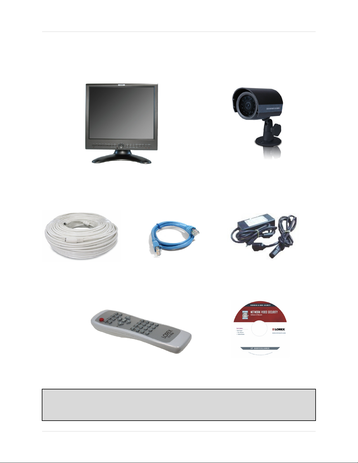
The SG17L7584 system comes with the following components:
17” Color 2 Page / 8 Channel Dual
Quad LCD Monitor
Cables (57’ Length)
Ethernet
Cable
4 x 1/4” CCD Color IR Day/Night
Cameras (with
Removable Sunshade)
Standard Power Cable4 x Camera
Remote Control NetViewer
Software
CHECK YOUR PACKAGE TO CONFIRM THAT YOU HAVE RECEIVED THE COMPLETE
SYSTEM, INCLUDING ALL COMPONENTS SHOWN ABOVE.
8
Page 9
SG17L7584 - Front - Primary Function Buttons
SG17L7584 - Front - Primary Function Buttons
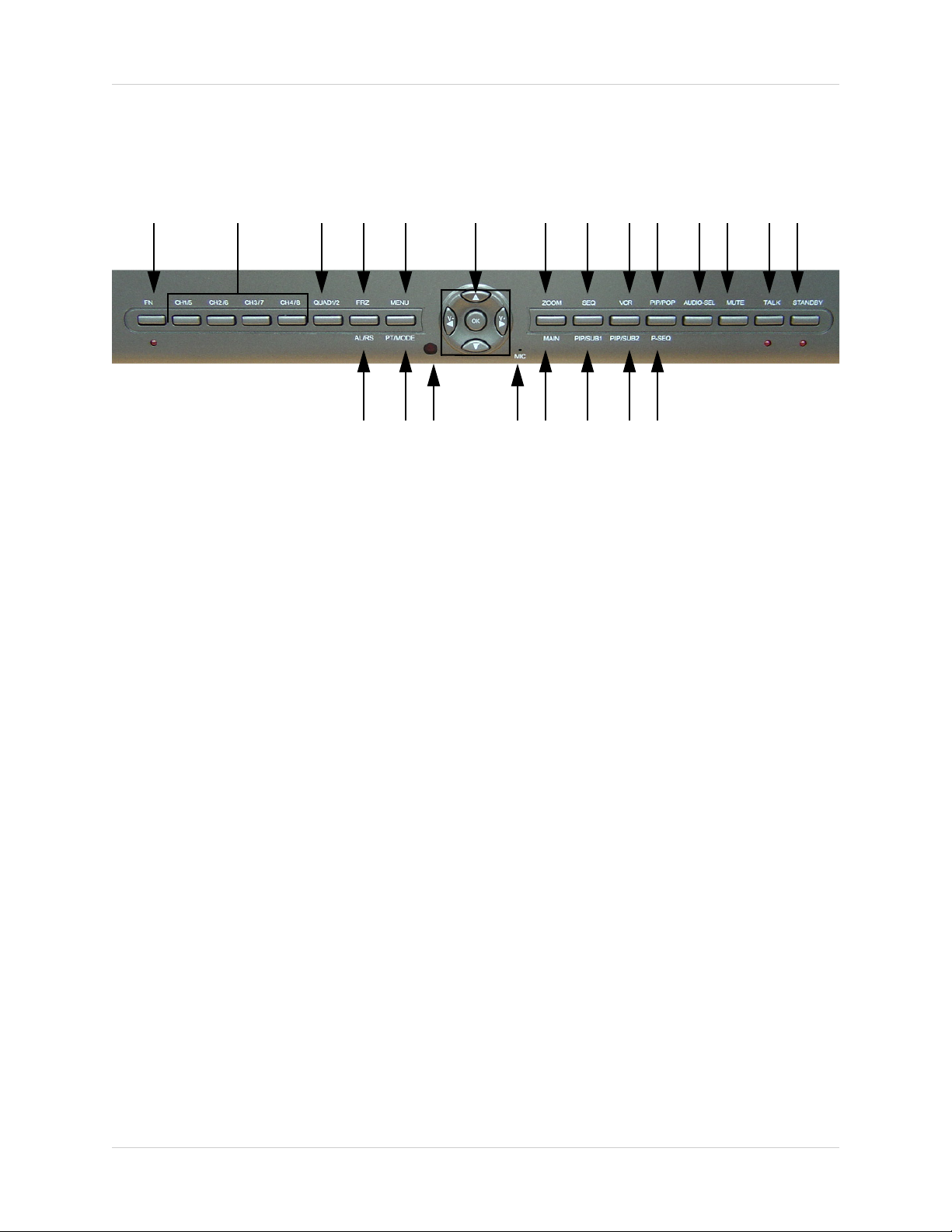
1 2 3 4 5 6 7 8 9 10 11 12 13 14
15 16 17 18 19 20 21 22
1. FN (FUNCTION) BUTTON - When this button is pressed, the LED below the button will turn
ON indicating that secondary function of the front panel buttons can be activated.
To de-activate the secondary function for the buttons (and reactivate the primary functions),
press the button [FN] button again and the LED will turn off.
2. CAMERA SELECT BUTTONS (CAM1/5 - CAM4/8) - Pressing a camera button will display
video from the selected camera in the FULL SCREEN of the monitor.
• To view live video from Camera 1, press the Cam 1 button.
• To view live video from Cameras 2-4 in FULL SCREEN mode, press the CH2, CH3 or CH4
buttons
• To view live video from Cameras 5-8 in FULL SCREEN mode, press the FN BUTTON (the
red LED below the FN button will be lit), and press the CH5 - CH8 Buttons.
3. QUAD 1/2 BUTTON - Displays 4 channels in Quad Mode.
• Press the [QUAD] button to display the CAM 1 - CAM 4 cameras in 4 equal Quadrants on
the monitor.
• Press the FN button (the red LED below the FN button will be lit), and Press the [QUAD]
button to display the CAM 5 - CAM 8 cameras in 4 equal Quadrants on the monitor.
To exit Quad mode (and return to Full Screen mode), press a CAMERA SELECT button.
9
Page 10
SG17L7584 - Front - Primary Function Buttons
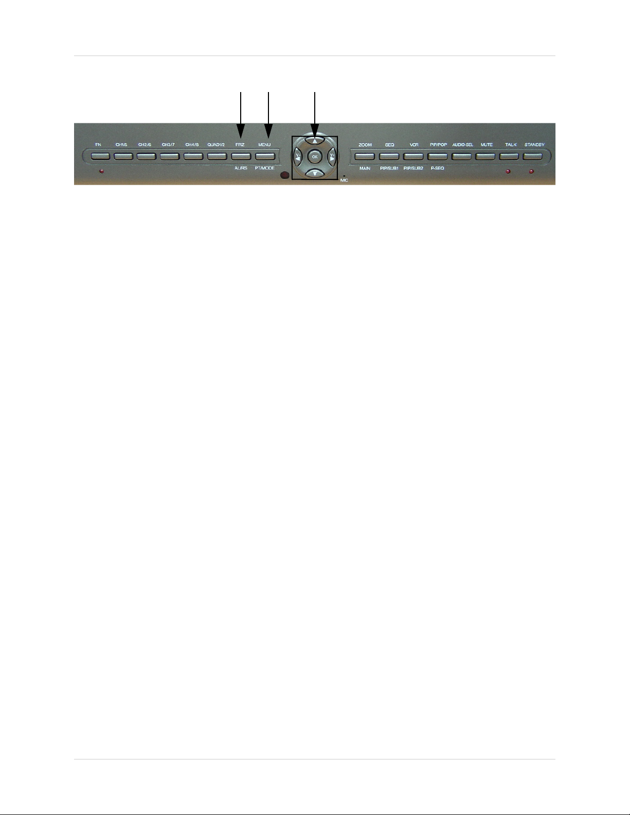
45 6
4. FRZ ALL BUTTON - The function of the FRZ ALL (Freeze All) button is to digitally freeze the
image that is being displayed on the monitor. To freeze an image:
• Press the [FRZ] button while viewing a FULL SCREEN single camera in live video. This will
freeze the camera image being viewed.
• Pressing the [FRZ] button while in Quad mode. This will freeze all four cameras displayed on
the monitor. An "F" will appear in the On-Screen Display.
• To return to live video, press the [FRZ] button again.
5. MENU BUTTON - Press the [Menu] button to enter the menu option screen. For further details
on MENU OPTIONS, please refer to Page 22
6. NAVIGATION BUTTONS - The Navigation buttons are used under multiple circumstances:
• In the Menu Mode, the Navigation buttons are used to scroll LEFT / UP / DOWN / RIGHT.
When a menu option is selected, they are also used to scroll though the various options. The
[OK] button in the center confirms selections in the Menu mode
• In the Zoom Mode, the Navigation buttons are used to select the region to zoom in (LEFT
/ UP / DOWN / RIGHT).
• In the PTZ Mode, use the Navigation buttons to PAN sideways. Press OK to select whether
to MOVE / ZOOM / FOCUS the PTZ Camera
• Volume Control: In the live viewing mode, the LEFT / RIGHT navigation buttons are used
to lower / raise the volume.
.
10
Page 11

SG17L7584 - Front - Primary Function Buttons
789
7. ZOOM BUTTON - This monitor is equipped with 2 times digital ZOOM. To utilize this feature
proceed as follows:
• Set the monitor to full screen mode or Quad mode for the desired channel
• Press the ZOOM button. ZOOM mode is now active
• Use the Navigation Buttons [
ÇÈÅÆ ] keys to move the area being captured in 2x ZOOM
MODE.
• To exit ZOOM MODE, press the ZOOM button again.
8. SEQ BUTTON - This function is used to Sequence between all camera locations in Full Screen
mode in sequential order. The letters SEQ will appear in the on-screen display during sequencing
and QUAD MODE display.
• To change Sequence settings through the MENU, refer to Page 24.
• To exit Sequence Mode, Press the SEQ button again.
9. VCR / DVR BUTTON - Changes the display from the Live Mode Camera inputs to the DVR/
VCR Audio/Video playback and recording unit. To return to the normal viewing of the Camera
inputs, press [VCR] button again.
11
Page 12
SG17L7584 - Front - Primary Function Buttons
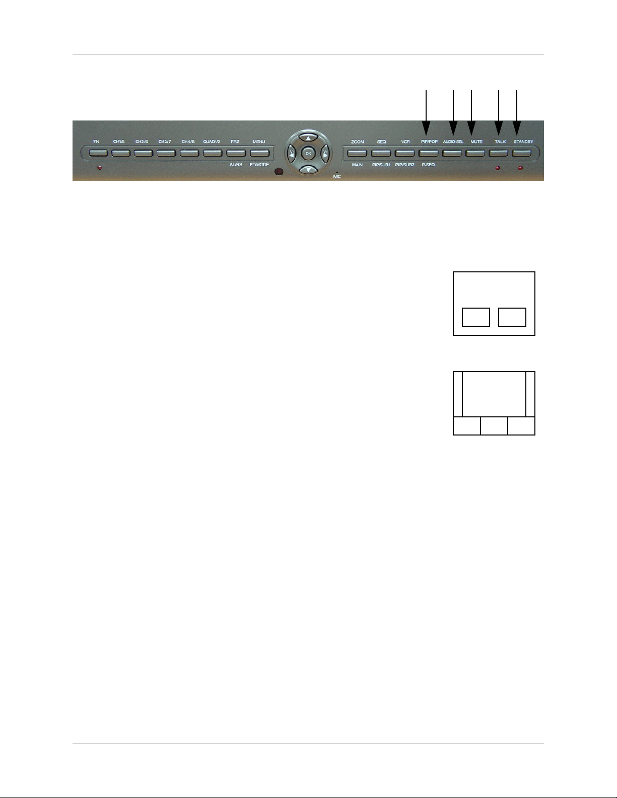
10 11 12 13 14
10. PIP POP BUTTON - Display a main camera image with secondary
camera sub-images:
• PIP (Picture In Picture) allows you to view three locations
simultaneously, one being the main channel, the others being viewed
as small images on the screen. To view detailed settings, see Main
Menu Controls on Page 25.
DUAL PIP
• POP (Picture on Picture) divides the screen into 4 screens, with the
main channel occupying two-thirds of the screen. Refer to the diagrams
adjacent that illustrates the difference between Dual PIP and POP.
Press the PIP/POP button to switch between the two functions. To
change these settings, See Main Menu Controls on Page 25.
POP MODE
11. AUDIO SEL BUTTON - In Quad Mode, the user can select the channel with audio. Pressing
this button automatically changes the audio from camera to camera. An icon indicates which
channel is currently receiving audio.
12. MUTE BUTTON - This button mutes audio. Press this button again to turn the audio feature
back ON.
13. TALK BUTTON - Press and hold this button to talk to a specific camera location. This button
must be pressed the entire time, while talking. To listen to the camera location, release the Talk
button.
NOTE: The supplied cameras DO NOT support this function. The supplied cameras support
LISTEN IN AUDIO only.
14. STANDBY BUTTON - This switch will turn the screen ON/OFF. A red LED indicator light is
ON when the monitor is in Standby mode. Press the button to turn the screen ON. Allow for 5-7
seconds for the picture to appear.
NOTE: To provide longer life to the CRT monitor, press the Standby switch when the system is
not in use (turns off the screen). The system will continue to record images to the DVR/VCR.
12
Page 13
SG17L7584 - Front - Secondary Function Buttons
SG17L7584 - Front - Secondary Function Buttons
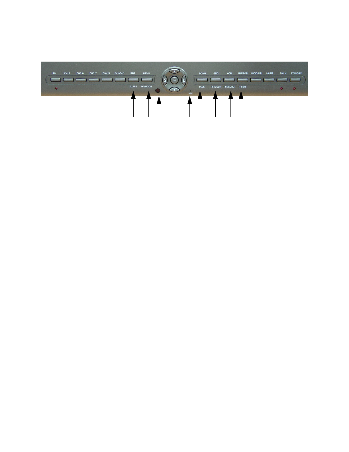
15 16 17 18 19 20 21 22
15. ALRS (ALARM RESET) BUTTON - To reset an alarm when it is active, press the [FN] button
to activate the secondary functions (note that the LED below the button will turn on), and press
the ALRS button. The alarm will be reset.
16. PAN / TILT BUTTON - Press the [FN] button to activate the secondary functions followed by
the [PT Mode] button to activate the Pan/Tilt functions for Channel 1.
NOTE: Accessory PTZ Camera model SG7380 is required to operate this feature.
17. IR RECEIVER - Infrared receiver for optional Remote Control
18. MIC - Enable TWO-WAY AUDIO with select LOREX cameras
19. MAIN BUTTON - Pressing the Main button while in the PIP, Dual PIP or POP mode will change
the camera input of the main screen being displayed.
20. SUB 1 BUTTON - Press the FN button to activate the secondary function, then press the SUB
1 button. This button is used to select the camera that is displayed in the 1st PIP window.
21. SUB 2 BUTTON - Press the FN button to activate the secondary function, then press the SUB
2button. When the Dual PIP mode is selected, this button is used to change the camera that is
displayed in the 2nd PIP window.
22. P-SEQ BUTTON (PIP SEQUENCE) - This button is used to sequence the small image or main
image in PIP mode, Press the [FN] button while in PIP mode or POP mode, this function will be
active. To exit PIP sequencing, press this button again.
13
Page 14
SG17L7584 - Back
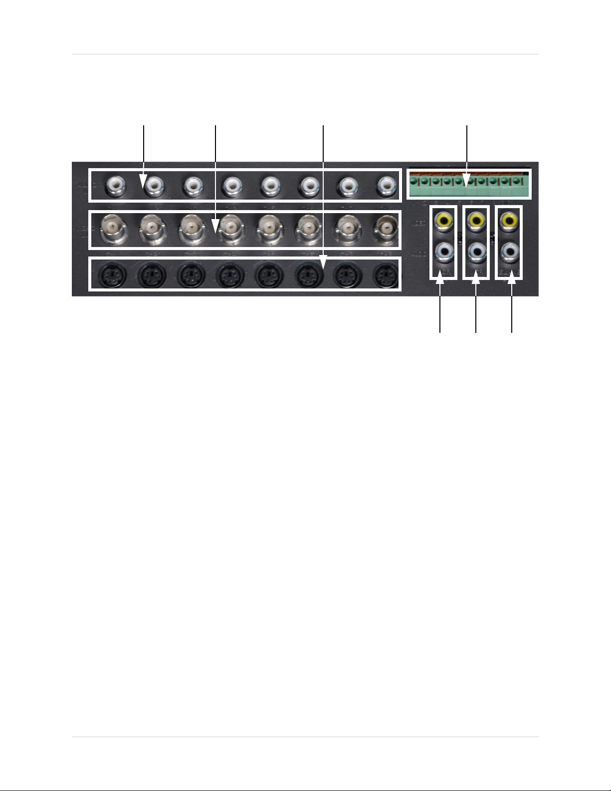
SG17L7584 - Back
12 3 4
567
1. RCA AUDIO INPUTS - Channel 1-8 Audio inputs (for non-DIN type cameras with standard RCA
Audio output).
2. BNC VIDEO INPUTS - Channel 1-8 camera inputs (used to connect Cameras with BNC
connection type), or can be used for Looping Video Output to a DVR
NOTE: When DIN type cameras are connected on a channel, the BNC CONNECORS serve
as LOOPING VIDEO OUTPUTS, and will send video to another device (such as a DVR or
SLAVE MONITOR).
3. 6 PIN DIN CAMERA INPUTS - Channel 1-8 Camera inputs (for cameras with 6 pin DIN
connection). Cameras can be connected using either 6 PIN DIN or BNC (Video) and RCA (Audio)
terminals.
4. ALARM FUNCTION TERMINALS (INPUT/OUTPUT) - These terminals are used to connect
external alarm devices such as a motion sensor, door/alarm sensor, or time lapse VCR for Alarm
Recording.
5. DVR / VCR AUDIO AND VIDEO IN - Use with A/V cables (not supplied) to receive audio and
video from an external source (DVR/VCR)
6. DVR / VCR AUDIO AND VIDEO OUT - Use the A/V cables (not supplied) to send audio and
video from the monitor to a DVR/VCR
7. SLAVE A/V OUT - Audio/Video Output signal for transmitting to a slave Monitor or VCR
14
Page 15
SG17L7584 - Back
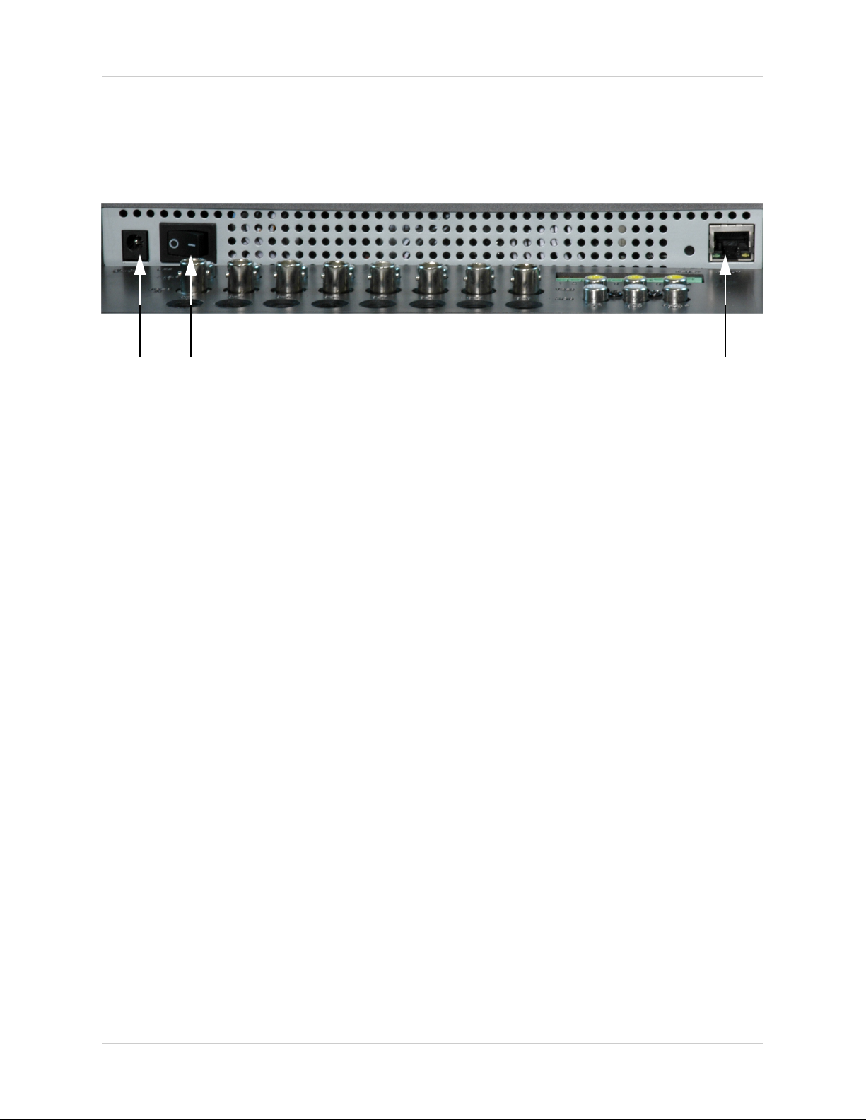
SG17L7584 - Back
Additional controls can be accessed by tilting the monitor forward.
12 3
1. AC INPUT - Connect the AC power (using the power cord provided with the unit) from the monitor
to an electrical outlet
2. POWER SWITCH - This button controls power to the entire unit. Depress the side with the ‘I"
to turn power ON. Depress the other side to turn the unit OFF
3. ETHERNET PORT - Connects the monitor to a router for connection to the internet. Refer to
the Netviewer Instructions on Page 33 for Remote Connection.
15
Page 16
Remote Control
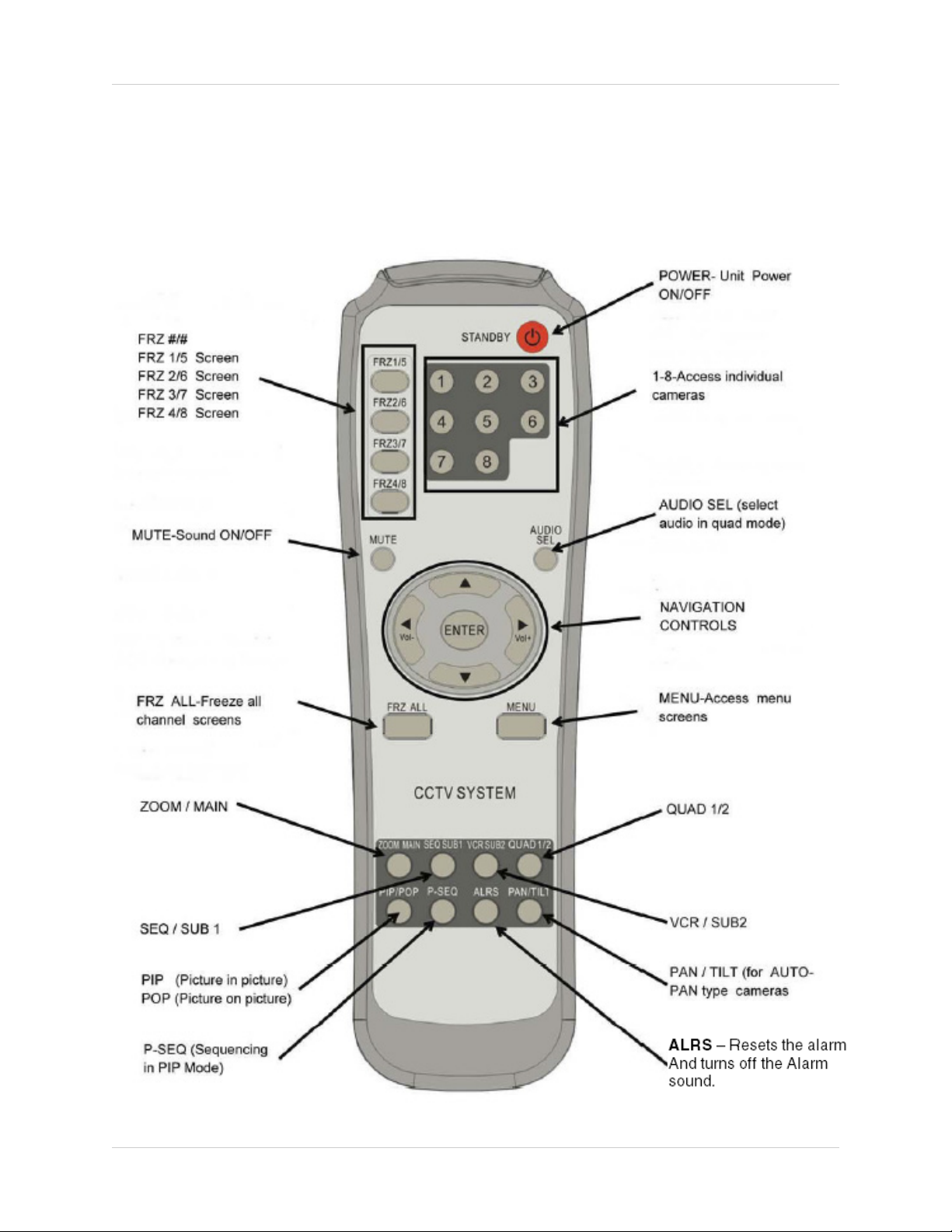
Remote Control
Listed below is a quick reference for the Remote Control. For details on specific features, refer to
the SG17L7584 - Primary / Secondary Buttons on Pages 10-14.
16
Page 17

Installing Cameras
Installing Cameras
The SG17L7584 Observation System includes 4 - 1/4” CCD Color IR Day/Night Indoor/Outdoor
Cameras*
INFRA-RED LEDs Provides illumination for low
light conditions
CAMERA LENS Delivers CCD Color image
to the Observation System
using a 6mm lens
MICROPHONE Picks up sound near the
camera and transmits to the
Observation System
INPUT CABLE (BACK) -
Delivers Video / Audio /
Power from the Observation
System to the Camera
BRACKET -
Metal bracket connects to
the Camera for mounting to
walls, ceilings and other
surfaces
* Picture changes from Color to B&W under low light conditions.
Mounting Bracket Installation
1. Attach the pedestal to the ceiling, wall or
other surface by the base using the
provided screws.
2. The mounting bracket must be attached to
a structural device such as a wall stud or
ceiling rafter using the supplied screws.
3. Attach the camera to the pedestal
Adjust the angle of the camera, and tighten
the thumbscrew to set the position
Installation Warnings:
• Install the camera away from direct sunlight.
• Avoid places where humidity is high, or where the camera cannot
adequately be protected from the rain or other elements.
17
Page 18

Connecting Cameras
Connecting Cameras
The SG17L7584 Observation System includes 4 x 1/4” Color CCD DIN Cameras. Additional
cameras can be added to the 4 additional camera inputs using the DIN or BNC ports.
DIN Connected Cameras
4 x 1/4” COLOR CCD DIN cameras are
included with the Observation System.
These cameras have a single cable, and
receive power directly from the
Observation System. The DIN ports are
located on to the bottom row of inputs,
and are labeled as CH1 - CH8
To Connect the Cameras to the Monitor:
1. Connect the female end of the supplied
57’ extension’ cable to the camera
OBSERVATION SYSTEM
2. Connect the male end of the supplied
57’ extension cable to an open DIN
channel on the back of the Observation
System
Continue connecting additional DIN
cameras.
BNC Connected Cameras
BNC connected cameras are not
included with the Observation System,
however can be ordered online at
www.lorexcctv.com
BNC Cameras have several cables and
receive power from a wall outlet
1. Connect the Video cable to an open
BNC Video Port (middle row of ports)
on the back of the Observation System
labeled CH1 - CH8
2. Connect the Audio cable to correspond
to the Audio port (top row of ports) on
the back of the Observation System
matching the port connected in step 1
3. Connect the AC power and camera ,
and connect the AC Adapter to an
electrical outlet
DIN Connected
Camera
(4 x 1/4” CCD
Included)
Power
BNC Connected
Camera
(Optional)
18
Page 19

Monitor Features
The SG17L7584 Observation System has adjustable tilt and height positioning.
The height can be adjusted using the thumbscrews at the base.
Monitor Features
• Loosen the thumbscrews (located on the lower left and right
sides of the base)
• Adjust the Monitor to the desired height
• Tighten the screw to hold the Monitor positioning
Thumbscrews
The Monitor can be tilted at a 45° angle (where the base
meets the monitor). Tilting the Monitor gives easy access
to the additional connection ports (Power and Ethernet
Connection).
Monitor Tilting
Point
19
Page 20
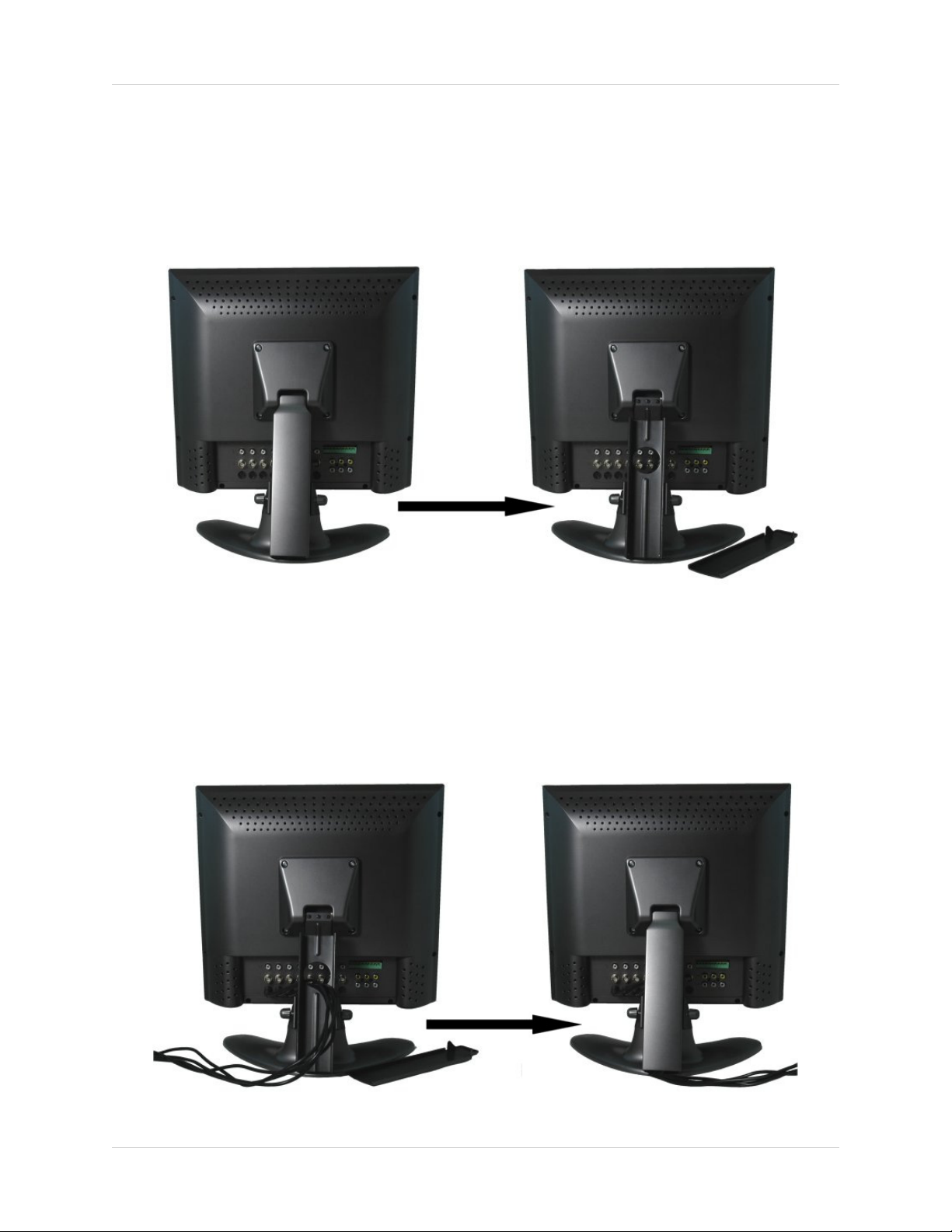
Cable Channel
Cable Channel
The SG17L7584 Observation System comes with a built in cable channel to easily organize and
conceal wiring.
1. Remove the Cable Channel Cover.
2. Connect the Power Cable, Cameras, Ethernet Cable and any Alarm Devices to the System by
running the cables through the hole in the stand before connecting to the Observation System.
3. Once all cables have been connected to the System, replace the Cable Channel cover.
20
Page 21

Main Menu Control
Main Menu Control
Enter the MENU screen by pressing the MENU button. Scroll through the 9 options by pressing
the UP and DOWN buttons. To enter a sub-menu, navigate to the option and press the OK
button. To exit a SUBMENU, select the RETURN option (and press the OK button) which takes
you back to the MAIN MENU. To exit the MAIN MENU, select the EXIT option from the
sub-menu (and press the OK button).
Outlined below are the buttons used to access menu settings:
KL
: Scroll up and down within a menu option
OK
: Press this button to select and change the values in a menu option
MENU
NOTE:
After 60 seconds of inactivity in the Menu mode, the system will go back to the previously
displayed live camera screen
: Complete modifications of a menu option; exit a menu
TIME/DATE
SEQUENCE
PIP/POP
TITLE
ALARM
MOTION
SYSTEM
MONITOR
EXIT
Set the Date and Time display
Camera sequence setup
Picture In Picture / Picture On Picture Setup
Change Camera descriptions
Alarm setup options
Setup of Motion Detection
Observation System preference setup
Adjust Monitor picture display settings
Exit to Camera view
[MAIN MENU CONTROL]
01. TIME/DATE SET
02. SEQUENCE SET
03. PIP/POP SET
04. TITLE SET
05. ALARM SET
06. MOTION SET
07. SYSTEM SET
08. MONITOR SET
09. EXIT
21
Page 22

Time / Date Set
Time / Date Set
This submenu allows you to change the TIME and DATE displayed on the monitor (On Screen
Display), and recorded through an optional DVR / VCR.
1. DISP MON - Display the DATE / TIME on the
monitor screen. Available options include Y and N.
To set this feature, navigate by pressing the
L buttons to highlight, and press the OK button to
switch between Y and N.
2. DISP REC - Display the DATE / TIME on the DVR
recording. Available options include Y and N. To
set this feature, navigate by pressing the
buttons to highlight, and press the OK button to
switch between Y and N.
3. TIME - Change the display TIME. To set this
feature, navigate by pressing the
to highlight, and press the OK button to select.
Navigate between the HH/MM/SS columns using
I and J buttons, and use the K and L buttons
the
to change. Press the OK button to complete the
change.
K and L buttons
K and
K and L
[TIME/DATE SET]
DISP MON
DISP REC
TIME
DATE
DATE FORMAT
RETURN
EXIT
:
[Y]
:
[Y]
:
10:45:08
:
01/01/2006
:
MM/DD/YYYY
:
[
]
:
[
]
4. DATE - Change the display DATE. To set this
feature, navigate by pressing the
to highlight, and press the OK button to select.
Navigate between the MM/DD/YYYY columns
using the
buttons to change. Press the OK button to accept
the change.
5. DATE FORMAT - Change the way the DATE is
displayed. To set this feature, navigate by pressing
the
button to scroll through the available options: MM/
DD/YYYY, YYYY/MM/DD and DD/MM/YYYY
6. RETURN - Return to the MAIN MENU. Navigate
by pressing the
press the OK button to select
7. EXIT - Return to the camera view. Navigate by
pressing the
press the OK button to select
I and J buttons, and use the K and L
K and L buttons to highlight, and press the OK
K and L buttons to highlight, and
K and L buttons to highlight, and
K and L buttons
22
Page 23

Sequence Set
Sequence Set
This submenu allows you to change the length of time a camera is displayed while the
SEQUENCE (SEQ) feature is enabled. When in SEQUENCE mode, the observation monitor cycles through available cameras in the sequence shown below.
NOTE: If a camera is set to 0 SEC, it will be skipped
in the AUTO SEQUENCING. Any channel without
an attached camera will be skipped automatically.
1. QUAD-A - Shows cameras 1 - 4 in QUAD screen
mode. To change the length of display time, press
K and L buttons to highlight, and press the OK
the
button to select the function. Press the
buttons to change the number of display seconds,
and press the OK button to accept the change
2. CH1 - CH4 - Shows cameras 1 - 4 in FULL
SCREEN screen mode. To change the length of
display time, press the
and press the OK button to select the function.
Press the
of display seconds, and press the OK button to
accept the change
3. QUAD-B - Shows cameras 1 - 4 in QUAD screen
mode. To change the length of display time, press
K and L buttons to highlight, and press the OK
the
button to select the function. Press the
buttons to change the number of display seconds,
and press the OK button to accept the change
K and L buttons to change the number
K and L buttons to highlight,
K and L
K and L
QUAD-A
CH1
CH2
CH3
CH4
QUAD-B
CH5
CH6
CH7
CH8
RETURN
EXIT
[SEQUENCE SET]
:
03 SEC
:
03 SEC
:
03 SEC
:
03 SEC
:
03 SEC
:
03 SEC
:
03 SEC
:
03 SEC
:
03 SEC
:
03 SEC
:
[
]
]
:
[
4. CH5 - CH8 - Shows cameras 1 - 4 in FULL
SCREEN screen mode. To change the length of
display time, press the
and press the OK button to select the function.
Press the K and L buttons to change the number
of display seconds, and press the OK button to
accept the change
5. RETURN - Return to the MAIN MENU. Navigate
by pressing the
press the OK button to select
6. EXIT - Return to the camera view. Navigate by
pressing the
press the OK button to select
K and L buttons to highlight, and
K and L buttons to highlight,
K and L buttons to highlight, and
23
Page 24

PIP/POP Set
PIP/POP Set
This submenu allows you to change the settings for PIP (Picture IN Picture) and POP (Picture ON
Picture). PIP displays small viewing screen(s) superimposed onto the larger main viewing screen,.
POP displays small viewing screen(s) along the top or bottom of the larger main viewing screen.
1. PIP SEQUENCE - Switch between SUB and MAIN
views. Navigate by pressing the
to highlight, and press the OK button to change
the PIP sequence mode
K and L buttons
[PIP/POP SET]
2. PIP POSITION - Changes the location of the PIP
(Picture In Picture) images. Navigate by pressing
K and L buttons to highlight, and press the OK
the
button to switch between PIP views:
[00] [01]
[02] [03]
PIP SEQUENCE
PIP POSITION
POP POSITION
RETURN
EXIT
:
:
:
:
:
[SUB]
[00]
[01]
]
[
]
[
3. POP POSITION - Changes the location of the POP
(Picture On Picture) images. Navigate by pressing
K and L buttons to highlight, and press the OK
the
button to switch between POP views:
[00] [01]
24
Page 25

Title Set
4. RETURN - Return to the MAIN MENU. Navigate
by pressing the
press the OK button to select
5. EXIT - Return to the camera view. Navigate by
pressing the
press the OK button to select
K and L buttons to highlight, and
K and L buttons to highlight, and
[PIP/POP SET]
PIP SEQUENCE
PIP POSITION
POP POSITION
RETURN
EXIT
:
:
:
:
:
[SUB]
[00]
[01]
[
]
[
]
Title Set
This submenu allows you to change the displayed description of the camera (8 character max.).
This is useful for identifying camera locations (i.e. “FRNT DR” (Front Door), “DOCK 1” (Loading
Dock #1), etc.) Available characters include A-Z, 0-9, and space.
1. DISPLAY - Sets the camera TITLE display on the
monitor. Navigate by pressing the
to highlight, and press the OK button to change
between Y and N. Selecting Y will display each
camera title, while selecting N will remove the
description from the ON SCREEN DISPLAY.
K and L buttons
[TITLE SET]
2. CH1 - CH8 - Set the TITLE for individual cameras.
To set the camera TITLE, navigate by pressing the
K and L buttons to highlight, and press the OK
button to select. Navigate by using the
buttons, and use the K and L buttons to select
numbers and letters. Press the OK button to accept
the change. There is a limit of 8 characters.
3. RETURN - Return to the MAIN MENU. Navigate
by pressing the
press the OK button to select
4. EXIT - Return to the camera view. Navigate by
pressing the
press the OK button to select
K and L buttons to highlight, and
K and L buttons to highlight, and
I and J
DISPLAY
CH1
CH2
CH3
CH4
CH5
CH6
CH7
CH8
RETURN
EXIT
:
[Y]
:
[C1]
:
[C2]
:
[C3]
:
[C4]
:
[C5]
:
[C6]
:
[C7]
:
[C8]
:
:
]
[
]
[
25
Page 26

Alarm Set
Alarm Set
This submenu allows you to configure the ALARM alert type and duration.This alarm type is used
in conjunction with external alarm input terminals. PIR cameras are offered by LOREX, but are not
included with this system.
1. ALARM - Configures the ALARM type for an alarm
event. Navigate by pressing the K and L buttons
to highlight, and press the OK button to switch
between DISPLAY modes:
• OFF - Alarm function is turned OFF
• OSD (On Screen Display) - When the alarm
occurs, the OSD displays [AL] in the
corresponding screen location.
• OSD + BUZZER - When an Alarm occurs, the
OSD [AL] appears on the corresponding
screen location, and a Buzzer will sound for the
set alarm period.
2. CH1 - CH8 - Set the alarm mode for cameras 1
through 8.
• Change the Alarm Interval - Navigate by
pressing the
number of seconds, and press the OK button
to select. Use the K and L buttons to change
the number of seconds for alarm display, and
press the OK button to accept the change.
• Press the
type OK button to change between alarm
modes. Alarm Modes include OFF (no alarm),
N/O (Normally Open) and N/C (Normally
Closed). Press OK to accept the change.
K and L buttons to highlight the
I and J buttons to highlight the alarm
ALARM
CH1
CH2
CH3
CH4
CH5
CH6
CH7
CH8
RETURN
EXIT
[ALARM SET]
:
[OFF]
:
10 SEC
:
10 SEC
:
10 SEC
:
10 SEC
:
10 SEC
:
10 SEC
:
10 SEC
:
10 SEC
]
:
[
]
[
:
[N/O]
[N/O]
[N/O]
[N/O]
[N/O]
[N/O]
[N/O]
[N/O]
NOTE: This N/O N/C Setting is for the external
alarm input terminal ONLY, and will not affect the
PIR cameras offered by Lorex.
3. RETURN - Return to the MAIN MENU. Navigate
by pressing the
press the OK button to select
4. EXIT - Return to the camera view. Navigate by
pressing the
press the OK button to select
26
K and L buttons to highlight, and
K and L buttons to highlight, and
Page 27

Motion Set
Motion Set
This submenu allows you to change the configurations for MOTION detection, using the monitors
built-in Pixel Based Motion Detection.
1. MOTION - Sets the motion detection alarm mode.
Navigate by pressing the
highlight, and press the OK button to switch
between MOTION alarm modes:
K and L buttons to
[MOTION SET]
• OFF - Motion Detection is disabled
• OSD (On Screen Display) - Visual alert only [MD]
• OSD + BUZZER - Both Visual and Audible alerts
2. CHANNEL - Configure the MOTION detect
settings for channel sets CH1/5, CH2/6, CH3/7 and
CH4/8. Navigate by pressing the
to highlight, and press the OK button to select the
channel to change. Once a channel has been
selected the SENSITIVITY and AREA can be
configured.
3. SENSITIVITY - Configure the sensitivity of the
MOTION detect. Navigate by pressing the
K and L buttons
K and
L buttons to highlight, and press the OK button to
set the SENSITIVITY mode from [00] to [05] (where
05 is the most sensitive setting). Press OK to
accept the selection.
MOTION
CHANNEL
SENSITIVITY
AREA
RETURN
EXIT
:
:
:
:
:
:
[OFF]
[CH1/5]
[02]
[00]
]
[
[
]
27
Page 28

Motion Set
4. AREA - Sets the area for motion detection.
Navigate by pressing the
highlight, and press the OK button to set the
MOTION detection area. Selections include:
K and L buttons to
[MOTION SET]
[01] [02]
[03] [04]
[05]
[00]
(FULL
SCREEN)
MOTION
CHANNEL
SENSITIVITY
AREA
RETURN
EXIT
:
:
:
:
:
:
[OFF]
[CH1/5]
[02]
[00]
]
[
[
]
5. RETURN - Return to the MAIN MENU. Navigate
by pressing the
press the OK button to select
6. EXIT - Return to the camera view. Navigate by
pressing the
press the OK button to select
28
K and L buttons to highlight, and
K and L buttons to highlight, and
Page 29

System Set
System Set
This submenu allows you to change the general preferences for the OBSERVATION SYSTEM.
1. KEY BUZZER - Sets the audible BUZZER that can
be heard when pressing any key to ON or OFF.
Navigate by pressing the K and L buttons to
highlight, and press the OK button to select Y or N.
[SYSTEM SET]
2. LOSS BUZZER - Sets the audible BUZZER ON/
OFF when a loss of channel signal is detected.
Navigate by pressing the
highlight, and press the OK button to accept
3. QUAD LINE - Enable / Disable the white dividing
lines on the QUAD screen. Navigate by pressing
K and L buttons to highlight, and press the OK
the
button to select Y or N
4. BLANK COLOR - Changes the background color
of the MENU screen. Navigate by pressing the
and L buttons to highlight, and press the OK button
to select BLUE, GREY or BLACK
5. VCR OUT - Sets the VCR out mode. Navigate by
pressing the
press the OK button to select ACTUAL (outputs
what is ON-SCREEN) or QUAD (outputs in QUAD
mode).
6. TITLE/TIME - Sets the on-screen location of the
Camera TITLE and TIME. Navigate by pressing
K and L buttons to highlight, and press the OK
the
button to select:
K and L buttons to highlight, and
K and L buttons to
K
KEY BUZZER
LOSS BUZZER
QUAD LINE
BLANK COLOR
VCR OUT
TITLE/TIME
PAN/TILT(CH1)
ALARM OUT
DEFAULT SET
RETURN
EXIT
:
:
:
:
:
:
:
:
:
:
:
[N]
[N]
[Y]
[BLUE]
[QUAD]
[TL/TR]
[N]
[N/O]
[N]
]
[
]
[
• TL/TR - Top Left / Top Right
• TL / BR - Top Left / Bottom Right
• BL/TR - Bottom Left / Top Right
• BL/BR - Bottom Left / Bottom Right
• TR/TL - Top Right / Top Left
• TR/BL - Top Right / Bottom Left
• BR/TL - Bottom Right / Top Left
• BR/BL - Bottom Right / Bottom Left
29
Page 30

System Set
7. PAN/TILT - Adjust the Pan / Tilt of the camera (PTZ
cameras only). Select Y if a PTZ camera is
connected.
[SYSTEM SET]
8. ALARM OUT - Set to N/O (Normally Open) or set
to N/C (Normally Closed).
9. DEFAULT SET - Set to Y to reset the unit to factory
defaults upon exiting the menu
10. RETURN - Return to the MAIN MENU. Navigate
by pressing the
press the OK button to select
11. EXIT - Return to the camera view. Navigate by
pressing the
press the OK button to select
K and L buttons to highlight, and
K and L buttons to highlight, and
KEY BUZZER
LOSS BUZZER
QUAD LINE
BLANK COLOR
VCR OUT
TITLE/TIME
PAN/TILT(CH1)
ALARM OUT
DEFAULT SET
RETURN
EXIT
:
:
:
:
:
:
:
:
:
:
:
[N]
[N]
[Y]
[BLUE]
[QUAD]
[TL/TR]
[N]
[N/O]
[N]
]
[
[
]
30
Page 31

Monitor Set
Monitor Set
This submenu allows you to change the picture settings for the OBSERVATION SYSTEM
MONITOR.
1. CONTRAST - Adjust the image contrast. Navigate
by pressing the K and L buttons to highlight, and
press the OK button to select. Press the
buttons to change the CONTRAST (maximum of
63). Press OK to accept the changes.
2. BRIGHT - Adjust the image brightness. Navigate
by pressing the
press the OK button to select. Press the
buttons to change the BRIGHT (maximum of 63).
Press OK to accept the changes
3. COLOR - Adjust the image color. Navigate by
pressing the
press the OK button to select. Press the
buttons to change the COLOR (maximum of 63).
Press OK to accept the changes
K and L buttons to highlight, and
K and L buttons to highlight, and
K and L
K and L
K and L
CONTRAST
BRIGHT
COLOR
TINT
SHARPNESS
RETURN
EXIT
[MONITOR SET]
:
:
:
:
:
:
:
[31/63]
[31/63]
[31/63]
[31/63]
[05/11]
[
]
]
[
4. TINT - Adjust the image contrast. Navigate by
pressing the
press the OK button to select. Press the
buttons to change the TINT (maximum of 63).
Press OK to accept the changes
5. SHARPNESS - Adjust the image sharpness.
Navigate by pressing the
highlight, and press the OK button to select. Press
K and L buttons to change the SHARPNESS
the
(maximum of 11). Press OK to accept the changes
6. RETURN - Return to the MAIN MENU. Navigate
by pressing the
press the OK button to select
7. EXIT - Return to the camera view. Navigate by
pressing the
press the OK button to select
K and L buttons to highlight, and
K and L
K and L buttons to
K and L buttons to highlight, and
K and L buttons to highlight, and
31
Page 32

NetViewer - Installation Requirements
NetViewer - Installation Requirements
The NetViewer software (included with the Observation System) has the following installation
requirements.
Minimum System Requirements:
Operating System Windows 2000
Windows XP Home Edition
Windows XP Professional
Processor .Pentium 4 - 1.5 GHz Processor (or equivalent)
Memory 256 MB RAM
Hard Drive 50 MB - Installation space required
* Additional Hard Drive space required for recording.
Recorded file size will vary depending on recording
quality settings
Recommended System Requirements:
Operating System Windows XP Home Edition
Windows XP Professional
Processor Pentium 4 / 3 GHz Processor (or equivalent)
Memory 1024 MB RAM
Hard Drive 50 MB - Installation space required
* Additional Hard Drive space required for recording.
Recorded file size will vary depending on recording
quality settings
Please refer to the NetViewer Installation Guide included with your Observation System for
further details.
32
Page 33
Network Connectivity
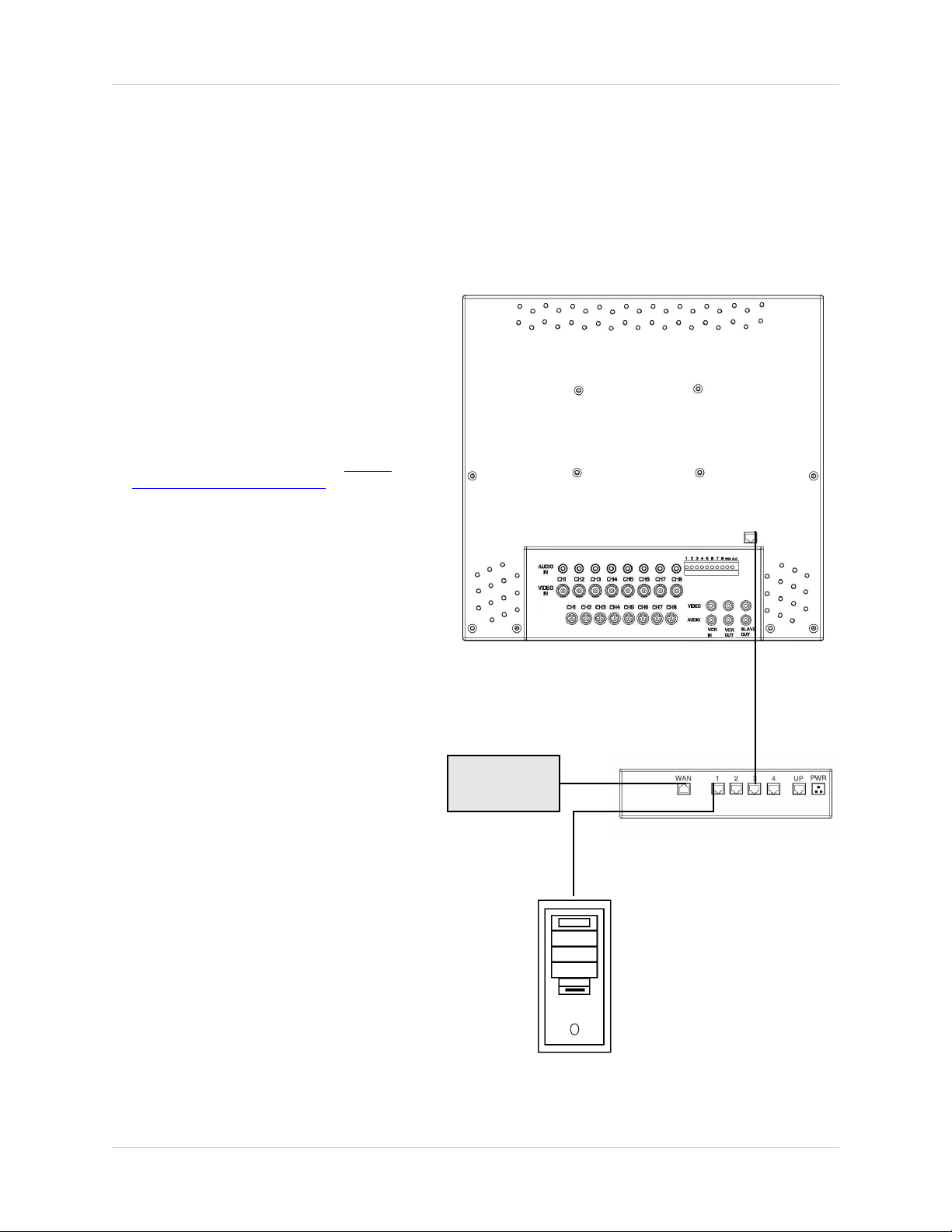
Network Connectivity
The SG17L7584 Observation System can be remotely controlled using your existing network and
the provided NetViewer software.
1. Connect the Observation System to
the Router using the supplied
Ethernet Cable. Power the
Observation unit on. You may need
to tilt the monitor forward to access
the Ethernet Port.
NOTE: The Observation System
must be connected to the router
prior to powering on the system.
This allows the system to
communicate on your network
2. Set up a web account at http://
DDNS.strategicvista.net. Refer to
Pages 35 - 36 for setup and
configuration instructions.
3. Install the NetViewer software on
your PC. See Page 33 for
installation requirements, and refer
to the provided ‘NetViewer Guide’
with your product for details on
using the software.
4. Find the IP address of your
Observation using the Lorex IPEdit
application. See Page 37 for details
OBSERVATION SYSTEM
5. Enable PORT FORWARDING on
your Router. Refer to the
instructions on Page 38 for details.
INTERNET
ROUTER
(Not Included)
PC
(Not Included)
33
Page 34
Setting Up Your DDNS Account
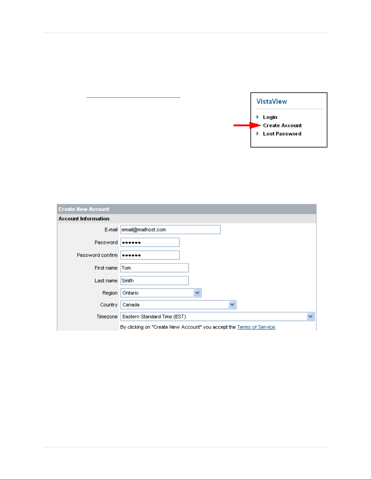
Setting Up Your DDNS Account
Lorex offers a free DDNS server for use with your System. A DDNS account allows you to set up
a web site address that points back to your Local Network. The following outlines how to set up
your free DNS account.
1. Navigate to http://DDNS.strategicvista.net
2. Select the Create Account option from the list on the left
side of the screen.
3. Complete the Account Information fields with your personal information
34
Page 35

Setting Up Your DDNS Account
4. Complete the System Information fields as follows:
• Product License: Select your product model from the Product
License drop down menu
• <Product Code> - <MAC Address>: Locate the MAC address
of your (recorded while loading the System)
• URL Request: Choose a URL for your DDNS connection (i.e.
your name, your company or business name, or anything of
your choice.)
NOTE: The URL request must not exceed 8 CHARACTERS
5. Click the Create New Account link at the bottom of the form to submit your request.
6. Your Account information will be sent to you at the E-mail Address you used in Step 3.
Service provider:
Domain name:
User name:
Password:
You will need this information for remote access to your System. Record YOUR
below:
Service Provider: _____________________________________________
Domain Name: _______________________________________________
User Name: _________________________________________________
Password: __________________________________________________
dns1.strategicvista.net
tomsmith.strategicvista.net
tomsmith1
<leave this field blank>
information
NOTE: The information sent to you in E-mail is CASE SENSITIVE. It is important
when setting up your DDNS information on your Observation System.
35
Page 36

Using the Lorex IPEdit Application
Using the Lorex IPEdit Application
The Lorex IP Edit application allows you to find and change the details of your Lorex
network device (i.e.. Observation System, DVR, or IP Camera).
1. Connect the LAN output of the OBSERVATION SYSTEM to your router using the provided
Ethernet cable.
2. Download the Lorex IPEdit application from the http://www.lorexcctv.com website
3. Double -click the application to run
4. A list of all detected Lorex Network Devices will be shown. Click on the name of the device on
the MONITOR LISTS section (left side) to populate the device data on the right side list
5. The IP address can be changed from this screen.
• Click on the IP address fields to change
• Click on SUBMIT to update the system IP address
Finding Your External IP Address
You will need to have your External IP address to set up your DDNS account. One of the fastest
ways to find this information is to use a 3rd Party website such as http://www.showmyip.com
Your IP address can also be found within your Router settings. Refer to your router user guide for
further details.
36
Page 37

Router Port Forwarding
Router Port Forwarding
How do I enable Port Forwarding on my Router?
You will need to enable port forwarding on your Router to allow for external communications with
your Observation System.
Computers, Observation Systems, and other devices inside your network can only communicate
directly with each other within the internal network. Computers and systems outside your network
cannot directly communicate with these devices. When a system on the internal network needs
to send or receive information from a system outside the network (i.e.. from the Internet), the
information is sent to the Router.
NETWORK EXAMPLE
Router
External IP
216.13.154.34
Internet
When a computer on the Internet needs to send data to your internal network, it sends this data
to the external IP address of the Router. The Router then needs to decide where this data is to
be sent to. This is where setting up Port Forwarding becomes important.
Port Forwarding tells the router which device on the internal network to send the data to. When
you set up port forwarding on your Router, it takes the data from the external IP address:port
number and sends that data to an internal IP address:port number (i.e Router External IP
216.13.154.34:5000 to Observation System Internal IP 192.168.0.3:5000).
Router
Internal IP
192.168.0.1
Internal Network
Computer
Internal IP
192.168.0.2
Observation
System
Internal IP
192.168.0.3
The instructions found online in the Router Configuration Guide
forwarding configurations for a selection of different router models.
Visit our Consumer Guides Support
website at http://www.lorexcctv.com for more details
will assist you in the port
37
Page 38

Troubleshooting
Troubleshooting
When a malfunction occurs, it may not be serious and can be corrected easily. The following
describes the most common problems and solutions. Please refer to the following before calling
your Observation System dealer
Problem:
Observation System Unit is not receiving power, or is not powering up
Check:
• Confirm that all cables are connected correctly
• Confirm that the ON/OFF (I/O) switch on the rear of the unit (beside the power cable connection)
is ON (in the I position)
• Confirm that there is power at the outlet:
z Connecting the power cable to another outlet
z Test the outlet with another plugged device (such as an electric calculator or
phone charger)
• If the unit is connected through a power bar or surge protector, try bypassing the bar and
connecting the power directly to the wall outlet
Problem:
Observation System is not responding when any of the buttons are pushed or does not come out
of STANDBY MODE
Check:
• Turn the master power switch OFF using the (I/O) switch on the rear of the unit (beside the
power cable connection):
z Press the (I/O) switch to the OFF position (O)
z Wait for 1 minute - all LED light indicators on the front of the unit will be off
z Press the (I/O) switch to the ON position (I)
The unit will make an audible alert when powered back on
38
Page 39

Troubleshooting
Problem:
The image on the Observation System is too dark or too bright
Check:
• Adjust the CONTRAST and BRIGHTNESS of the unit (Refer to the Menu section)
Problem:
The image on the Observation System appears, but does not have sound
Check:
• Check the VOLUME
• Check the CAMERA connection to the Observation System
• Confirm that the Camera has sound capabilities (Refer to the manual for the camera model
for further information on the Camera functionality)
Problem:
The picture on the Observation System is poor, shrinks or flickers
Check:
• Check the camera video cable and connections
• Disconnect and reconnect the cable at the Observation System and at the Camera
• Clean the camera lens
• Adjust the CONTRAST and BRIGHTNESS settings in the Menu (Page 32)
• Check that the Camera is not in direct sunlight
Problem:
There is no picture appearing on a Channel / Camera is not displaying
Check:
• Check the camera video cable and connections
• Disconnect and reconnect the cable at the Observation System and at the Camera
• Try moving the camera to another channel or use another cable
39
Page 40

Observation System Specifications - Appendix #1
Observation System Specifications - Appendix #1
Display
17” TFT LCD
Pixels (H x V) 1280 H x 1024 V
Pixel Arrangement RGB Vertical Strip
Pixel Pitch 0.264 x 0.264
White Luminance 260 cd/m
Contrast Ratio 450:1 (typical)
Camera Capable
Quad Speed 30 fps
Camera Input Any combination of 8 DIN / 8 BNC Cameras
Up to 8 Cameras
² (typical)
(up to 8 camera total)
Alarm Inputs / Outputs 8 / 2
Input Signal 1 Vp-p @ 75
Power Source Multi Voltage 100~240 VAC 50/60 Hz
Power Consumption 45 Watts
Operating Temperature 32
° F ~ 104° F
° C ~ 25° C
0
Color Metallic Grey
40
Page 41

Camera Specifications - Appendix #2
Camera Specifications - Appendix #2
Image Device
1/4" Interline transfer type color CCD
Effective Pixels 512 H x 492 V (252k PIXELS)
Scanning System 525 Lines 2:1 Interlace
Resolution Horizontal 350 TV lines
Shutter Speed 1/60 ~ 1/10,000 sec.
S/N Ratio More than 48dB (AGC off)
Sync. System Internal
Min. Illumination 1.0 Lux (without LED) / 0.1 Lux (with LED
White Balance AWB
Video Output VBS 1.0 Vp-p (75 ohms load)
Lens
Power Supply
Power Consumption
Operating Temp
Fixed Lens (6mm)
DC12V ±10% (from the monitor)
100mA (without LED) / 180mA (with LED)
14°F - 113°F ( -10°C - +45°C)
)
Weather Proof Rating
Operating Humidity
As our products are subject to continuous improvement, LOREX Technology Inc. and its
subsidiaries reserve the right to modify product design, specifications and prices, without notice
IP44
90% RH max.
and without incurring any obligation.
E&OE
41
Page 42
Connecting to a Single Channel DVR / VCR - Appendix #3
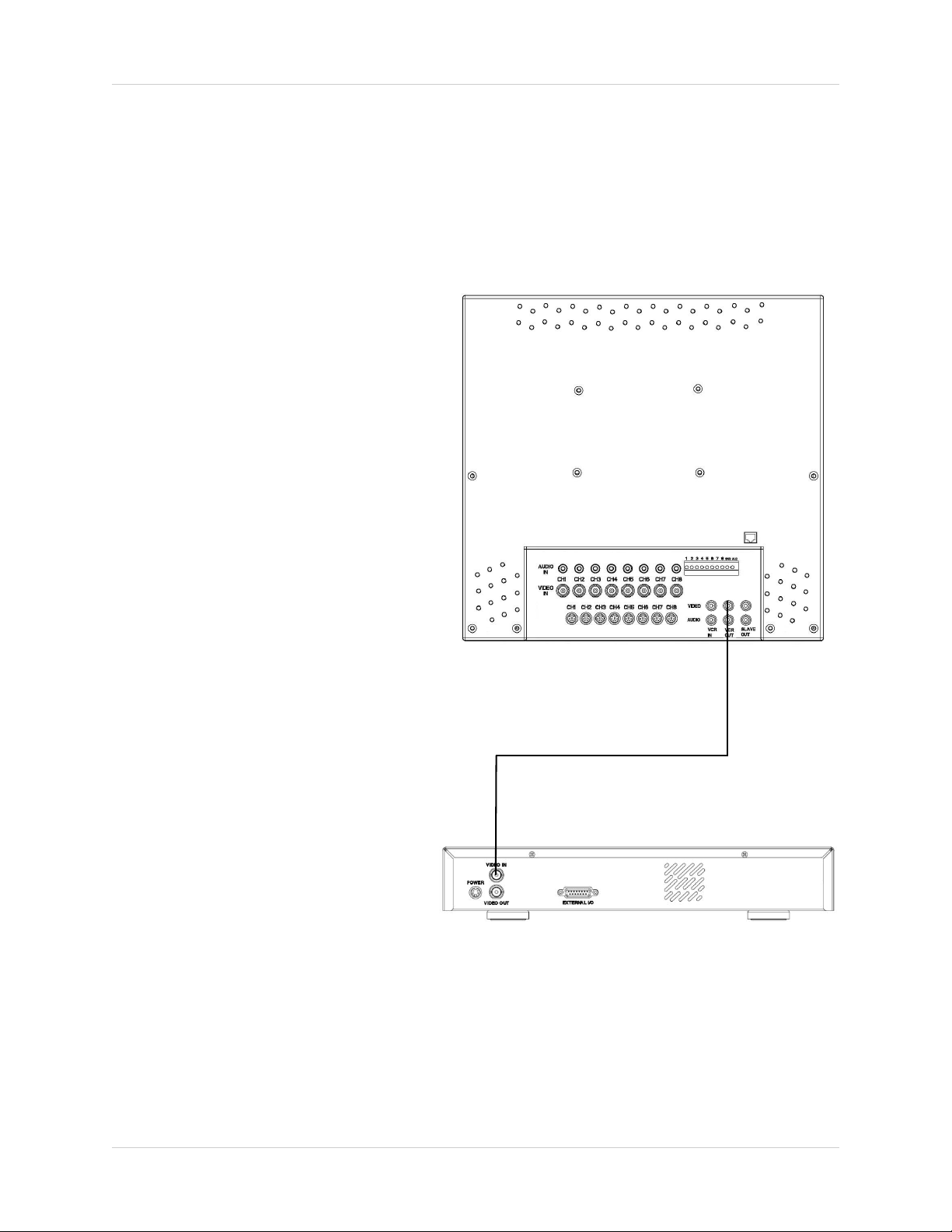
Connecting to a Single Channel DVR / VCR - Appendix #3
The SG17L7584 Observation System can be used with a Single Channel DVR or VCR unit (not
included)
1. Connect the Video cable from the
VIDEO OUT port on the
Observation System to the VIDEO
IN port on the DVR or VCR Unit
2. Connect the AUDIO cable from the
AUDIO OUT port on the
Observation System to the AUDIO
IN port on the DVR or VCR unit (if
available)
DVR NOTE:
When recording to a Digital Video Recorder, the DVR may indicate a Video
Loss as the monitor sequences between channels. This Video Loss occurs because the monitor’s switching
function is analogue, whereas the
DVR is a digital product. Therefore a
synchronization problem will result.
The solution to this problem is to adjust the Video Loss alarm sensitivity
setting to 3 frames on your DVR unit,
or simply disable the video loss function on your DVR. Please refer to the
manual for your specific model of
DVR for further information.
OBSERVATION SYSTEM
VCR NOTE:
Ensure the Standard VCR channel is
set to A/V Mode in order to ensure reception. Consult the manual for your
specific VCR for setting the A/V settings.
NOTE: VCR OUT ports are used for
connecting recording devices (such
as a DVR). SLAVE OUT ports are
used for connecting display devices
(such as a Slave Monitor)
42
SINGLE CHANNEL DVR OR VCR
(Not Included)
Page 43

Connecting to a Multi-Channel DVR - Appendix #4
Connecting to a Multi-Channel DVR - Appendix #4
The SG17L7584 Observation System can be used with a Multi-Channel DVR (not included). A
Multi-Channel DVR enables you to record multiple video streams with a single device
NOTE: The CH1 - CH8 BNC Video inputs serve as Looping Video Outputs
by individual channels when a DIN
camera is connected to the associated channel.
1. Attach the BNC to RCA
(Male to Female)
adapters on the BNC
CH1-CH8 found on the
Observation System.
2. Attach the BNC to RCA
(Male to Female)
Adapters on the BNC
CH1-CH8 found on the
DVR
3. Connect the standard RCA cables
from the Observation System to the
DVR.
4. Connect the Audio Cables from the
Observation System CH1-CH8 to
the DVR CH1-CH8
RCA to BNC
Adaptor
OBSERVATION SYSTEM
5. Connect cables from the DVR
Video / Audio Out to the VCR IN
(Video and Audio) on the
Observation System
To switch from viewing the
Observation System to viewing the
DVR, press the VCR button on the
front panel of the Observation
System.
DVR UNIT
(Not Included)
43
Page 44

Connecting a Slave Monitor - Appendix #5
Connecting a Slave Monitor - Appendix #5
Connections to a Slave Monitor (not included) can be made through the SLAVE OUT ports on
the back of the Observation System
A Slave Monitor is used as a View
Only device. A Slave Monitor can
only display camera data as it is
shown on-screen on the Observation
System.
Specific controls for the Observation
System are configured through the
Menu Options
1. Connect the SLAVE VIDEO OUT
port on the back of the Observation
System to the VIDEO IN port on the
back of the Slave Monitor
2. Connect the SLAVE AUDIO OUT
port on the back of the Observation
System to the AUDIO IN port on the
back of the Slave Monitor
OBSERVATION SYSTEM
44
SLAVE MONITOR
(Not Included)
Page 45
Connecting Motion / Alarm Device - Appendix #6
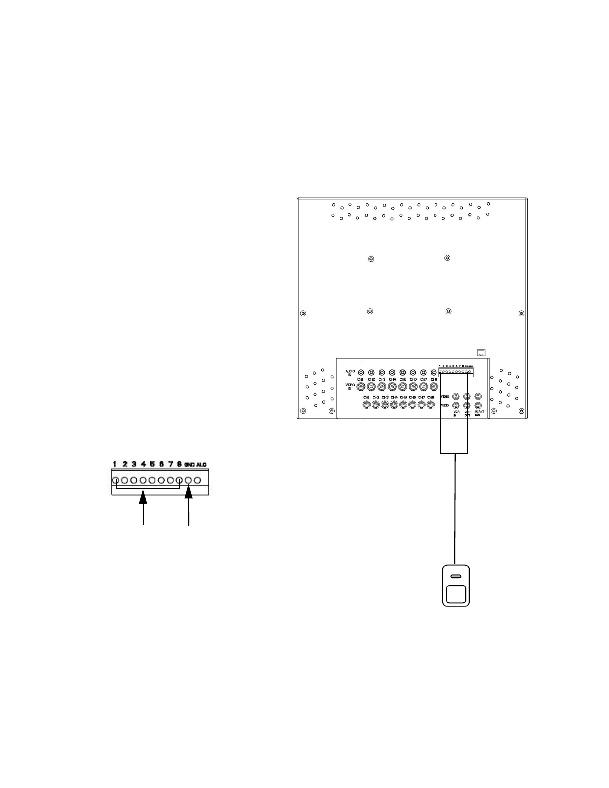
Connecting Motion / Alarm Device - Appendix #6
Motion detection and Alarm controls are enabled through the Menu system on the Observation
System. Additional motion sensor devices can be connected to the system (Motion Sensors,
Door/Window Sensors).
A motion detection or sensor unit can
be used to send a signal to the
Observation System to begin camera
viewing on the matching Video
Channel (when enabled in the
MENU/ALARM SET MODE)
• Example: A Window sensor unit
has been installed on Alarm
Block port #4. When this sensor
is activated, the camera on DIN
or BNC VIDEO port #4 will
become active (if enabled in the
MENU on the Observation
System)
For the corresponding Menu Programming, refer to Page 26.
Installing a Sensor
1. Connect the GROUND Cable to the
GND port on the Alarm Block on the
Observation System
OBSERVATION SYSTEM
2
2. Connect the SIGNAL Cable to a
numbered port (1-8)
To start ALARM RECORDING on a
DVR unit, refer to the manual for
your specific DVR product.
1
SENSOR
(Not Included)
45
Page 46

Full Connectivity Diagram - Appendix #7
Full Connectivity Diagram - Appendix #7
The following diagram outlines a general set of connections available with the SG17L7584
Observation System.
OBSERVATION SYSTEM
SENSOR
(Not Included)PC(Not Included)
4 x 1/4” CCD CAMERAS
(Included)
DVR UNIT
(Not Included)
ROUTER
(Not Included)
SLAVE MONITOR
(Not Included)
46
Page 47
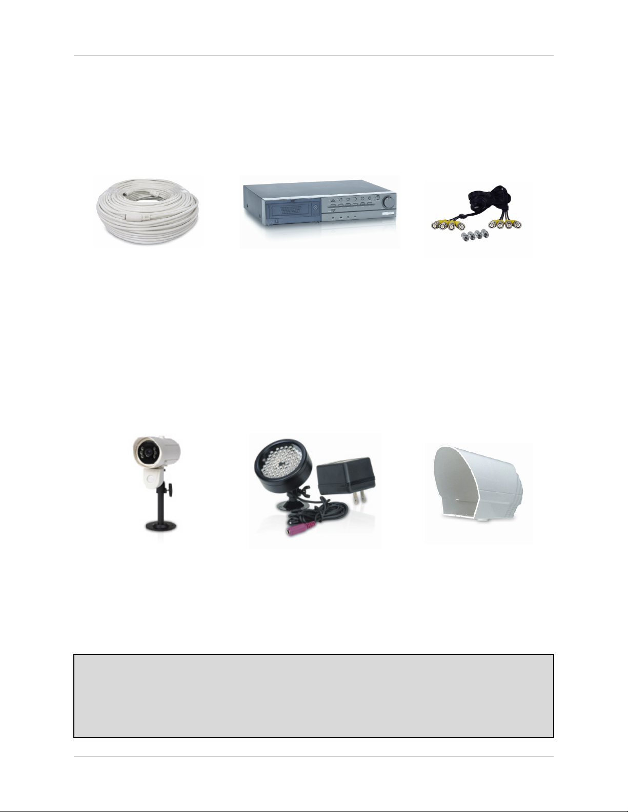
Optional Accessories
The following accessories are available to add to your existing system
Optional Accessories
CABLE
Extends the length
between the CAMERA
and MONITOR.
Available in 65’, 100’ and
250’ lengths
OBSERVATION
CAMERAS
DVR UNIT
Accessory DVR units - Record
and Replay from your
Observation System
CAMERA
ACCESSORIES
QUAD LOOPING
OUTPUT CABLE
Connects 4 video outputs
of a multi-channel CCTV
MONITOR to a 4 Channel
DVR
SUNSHADE
HOUSING
Accessory PIR motion
sensor
observation
system camera
TO ORDER THESE ACCESSORY ITESMS OR FOR A COMPLETE LISTING OF AVAILABLE
PRODUCTS, PLEASE VISIT US ON THE WEB AT:
Night Vision Accessory
with 68 LED
illuminators for viewing in
total darkness
Protects the
CAMERA from direct
sunlight (which pre-
vents over-
exposing the image)
WWW.LOREXCCTV.COM
47
Page 48

Optional Accessories
48
Page 49

It’s all on the web
Product Information
User Manuals
Quick Start Guides
Specification Sheets
Software Upgrades
Firmware Upgrades
VISIT
www.lorexcctv.com
Strategic Vista International Inc.
wwwlorexcctv.com
 Loading...