

Page 1
Power Up your Computer Remotely
QDR-TELS
QDR-TELS
USER GUIDE
USER GUIDE
( Version 1.0 )
( Version 1.0
QDR-TELS © 2003
Strategic Vista Corp.
Page 2

1. QDR-TELS Introduction
The QDR-TELS module is an accessory to the VISTAPRO 4 which allows you to power up/power down your
computer remotely via the telephone.
Note that you must also be using the I/O Alarm block with your VISTAPRO 4 in order to incorporate the
QDR-TELS.
1.1. Items in the Package
3 The QDR-TELS module
3 USB Cable
3 Telephone Cable
3 DC Power Adapter
3 User Guide
1.2. Features
1) Voice Prompting : The QDR-TELS uses Voice Prompts to guide the user through the features and
functions of the module.
2) PIN Protected: The module requires a PIN code before remotely turning on the PC.
Page 3

2. QDR-TELS Installation
Step 1: Connect the QDR-TELS to the I/O Alarm Block of the VistaPro 4
Using the USB Cable supplied, plug one end into the USB port found on the I/O Alarm Block (see
diagram) and the other end to the USB port found on the QDR-TELS module.
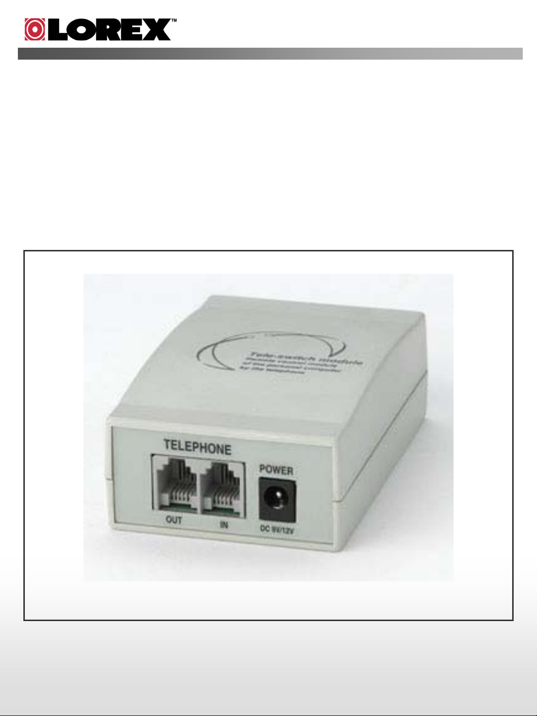
Step 2: Connect the QDR-TELS to the premises telephone line.
Using the supplied telephone cable, plug the RJ-11 modular plug into the ‘TEL IN’ RJ-11 jack,
(located on the back of the QDR-TELS Module). The other end of the telephone cable is then
plugged into a premise RJ-11 wall jack.
To connect a local telephone to the QDR-TELS, simply plug the cable from the telephone into the
‘TEL OUT’ RJ-11 Jack on the module.
Step 3: Power Up the Module
To apply power to the module, plug the power connector from the supplied Power Supply Adapter
into the Power Jack (located on the back of the QDR-TELS module). Plug the Power Cord into a
110/120 VAC outlet..
NOTE: By default, the system password is 0000 and the rings to answer is set at 3.
Page 4

3. Connection Diagram & Installation
PWR
LED
QDR-TELS
FRONT
USB
Port
RESET
Ribbon Cable Connector
to Connect VistaPro 4 with
I/O Alarm Block
QDR-TELS
TELEPHONE
OUT IN
POWER from PC
POWER from PC
Power Supply
Power Supply
BACK
POWER
DC 9V/12V
POWER PIN from
POWER PIN from
PC Motherboard
PC Motherboard
Page 5

NOTES:
In order for the QDR-TELS to operate properly, the VistaPro 4 and I/O Alarm Board must
already be installed in the PC with particular attention to the items below:
1. The VistaPro 4 main board and I/O board have to be connected each other.(I/O board cable
connector)
2. The power supply port for camera power on the VistaPro main board must be connected to
the PC Power Supply. (Power supply cable)
3. The Socket for ‘PC Power On Control’ of the VistaPro I/O Alarm board must be connected to
the Power Pin on the PC main-board (PC Power Pin connection cable -red cable).The other
side of this cable must be connected with the Power Switch connection cable on the front of
PC case.
DVR PC Power Pin Cable
DVR PC Power Pin Cable
PC Main-board
PC Main-board
DVR PC Power Pin
DVR PC Power Pin
Cable
Cable
Power Switch
Power Switch
cable connector
cable connector
from PC Front case
from PC Front case
For further instructions related to the installation of the VistaPro 4 and I/O Alarm Block,
please refer to the VistaPro 4 Installation and User Manual.
Page 6

4. Remotely Turning the PC ON/OFF using the QDR-TELS
1) Call the premise from a remote location.
2) After the designated number of rings, the module will pick up and request a PIN. If a valid PIN is
entered, the QDR-TELS module will prompt to the user the current status of the computer, (On or
Off). At this time, the user is presented with the following options.
when Computer is OFF
USER
1
Connecting telephone.Connecting telephone.
Remarkwhen Computer is ONOrder
Default : 3 timesRinging.Ringing.2
MSG
USER
MSG
5
" Computer is running now
" Press password "“ Press password "3
Press the password.
" Computer is off now "
Default : 0000Press the password.4
"
MSG
6
" Press 0 to turn-off
computer and Press 9 to
change ringing time ”
" Press 1 to run computer
and Press 9 to change
ringing time "
At this moment,
you can press 8 to
change password.
3) With following the Message, turn PC ON(‘0’) or OFF(‘1’) by pressing the number.
How to ON of PCHow to OFF of PCOrder
USER
7
MSG
8
Press the ‘1’.Press the ‘0’.
" Computer is on now. Thank you ”" Computer is turned off. Thank you
"
USER
9
Disconnecting.Disconnecting.
4) With following the Message, change the password(‘8’) or ring time(‘9’) by pressing the number.
Change Password
USER
7
MSG
Press the ‘8’.
" Press new password with 4-digit
Press the ‘9’.
" Press the number of ringing times ”8
Change Ringing timeOrder
buttons "
USER
10
11
12
13
NOTES:
1. In every step, a key must be pressed within 5 seconds of the prompt.
2. Password and / or rings to answer changes will not be saved if the call is terminated during a session.
3. To default the system, press and hold the reset key for more than 3 seconds. (The password will change to
MSG
USER
MSG
USER
0000, and rings to answer will default back to 3).
Press new password with 4-digit buttons.
" Press again please "
Press again.
" It is changed. Thank you ”
Press the number of ringing times.9
" It is changed. Thank you ”
---
---
DisconnectingDisconnecting
 Loading...