

Page 1
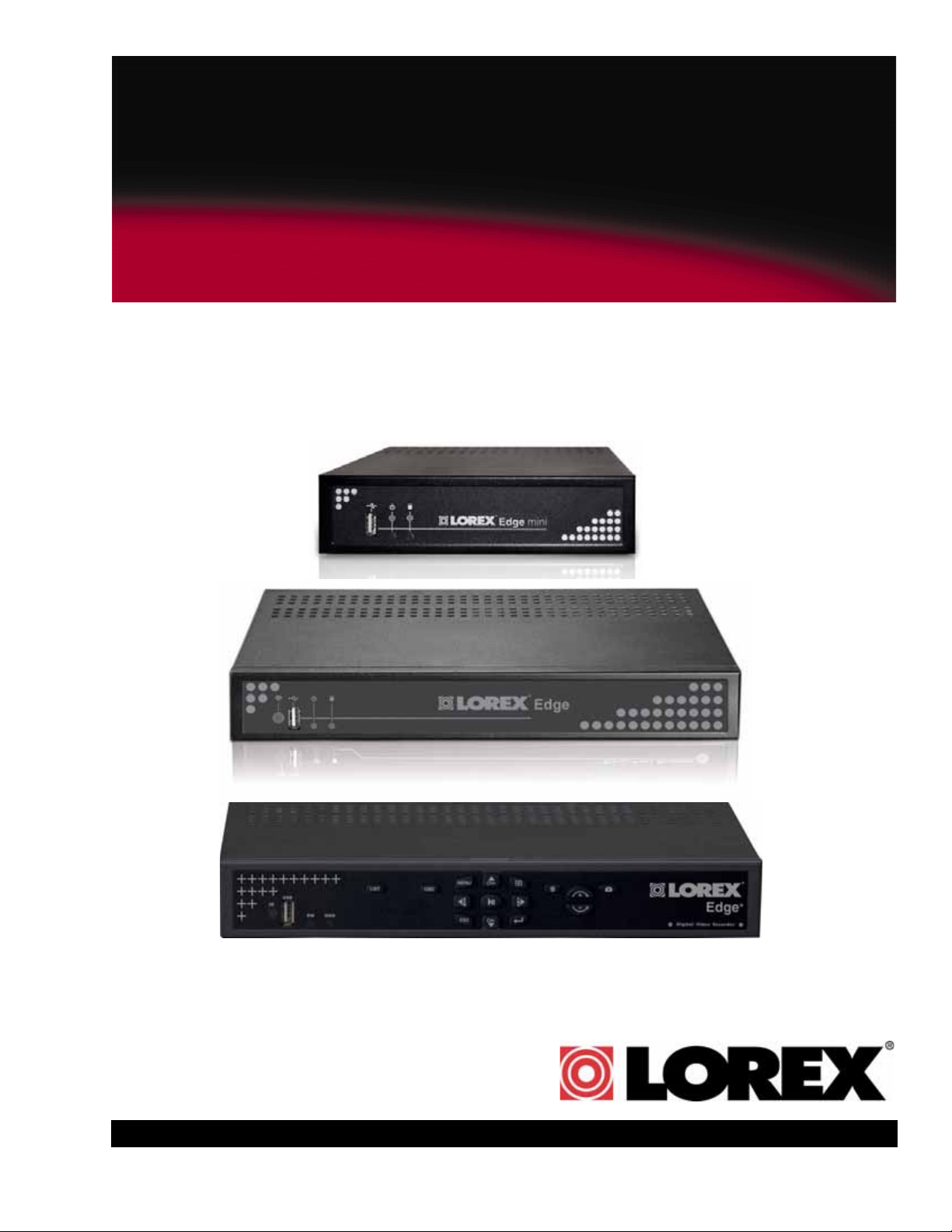
Lorex-Edge+ LH320 Series
Lorex Edge mini LH304 Series
Lorex EDGE LH310 Series
LOREX EDGE
NETWORK READY H.264 HIGH PERFORMANCE
DIGITAL VIDEO SURVEILLANCE RECORDER
INSTRUCTION MANUAL
English Version 2.0
MODEL:
LH300 SERIES
Copyright © 2010 Lorex Technology Inc.
www.lorextechnology.com
Page 2
Thank you for purchasing the LH300 Series Lorex-Edge H.264 Digital Video Surveillance
Recorder.
This manual refers to the following models:
To learn more about this product and to learn about our complete range of accessory
products, please visit our website at:
www.lorextechnology.com
CAUTION
RISK OF ELECTRIC SHOCK
DO NOT OPEN
CAUTION: TO REDUCE THE RICK OF ELECTRIC SHOCK DO NOT
REMOVE COVER. NO USER SERVICABLE PARTS INSIDE.
REFER SERVICING TO QUALIFIED SERVICE PERSONNEL.
The lightning flash with arrowhead symbol, within an equilateral
triangle, is intended to alert the user to the presence of uninsulated
"dangerous voltage" within the products ' enclosure that may be of
sufficient magnitude to constitute a risk of electric shock
The exclamation point within an equilateral triangle is intended to
alert the user to the presence of important operating and
maintenance (servicing) instructions in the literature accompanying
the appliance.
WARNING: TO PREVENT FIRE OR SHOCK HAZARD, DO NOT
EXPOSE THIS UNIT TO RAIN OR MOISTURE.
CAUTION: TO PREVENT ELECTRIC SHOCK, MATCH WIDE BLADE
OF THE PLUG TO THE WIDE SLOT AND FULLY INSERT.
• LH324 (4-channel)
• LH328 (8-channel)
• LH326 (16-channel)
• LH314 (4-channel)
• LH318 (8-channel)
• LH316 (16-channel)
Lorex Edge
Lorex EDGE
+
• LH304 (4-channel)
Lorex Edge mini
Page 3

NEED HELP?
CONTACT US FIRST
DO NOT R E T U R N THIS PRODUCT TO TH E STORE
Please make sure to register your product at www.lorextechnology.com to receive product updates and information
3 EASY WAYS TO CONTACT US:
Online:
Pr o du ct Su p po r t i s a va i l a b l e 2 4 /7 in c lu d in g p ro d uc t
in f or m at i on , us er ma n ua l s, q ui c k st a rt up gu i de s a nd FA Q ’s
at www.lo r extechnol o g y.com/suppor t
To o r de r a cc e ss o ri e s, v is i t
www.lo r extechnol o g y.com
By Email:
Te ch n ic a l Su p po r t ( fo r t e ch n i c al / in s ta l la t io n i ss u es )
sup p ort@lorex c orp.co m
Cu s to me r C a re (f o r w ar r a n ty an d a c ce s so r y s al e s)
cus t omerservice@lor excorp. com
Cu s to me r F e ed b ac k
inf o @lorexco r p.com
By Phone:
NORTH AMERICA:
CUSTOMER SERVICE: 1-888-425-6739 (1-888-42-LOREX)
TECH SUPPORT: 1-877-755-6739 (1-877-75-LOREX)
MEXICO: 1-866-427-6739
INTERNATIONAL: +800-425-6739-0
(Ex am p le : F rom t he UK, dia l 00 ins te ad of +)
Ve rs i o n 8 - A p r i l 2 7 2 0 10
Page 4

NECESITA AYUDA
VOUS AVEZ BESOIN
D’AIDE?
COMUNÍQUESE PRIMERO
CON NOSOTROS
NO DEVUELVA ESTE PRODUCTO A LA TIENDA
Cerci órese d e por f avor co locar s u produ cto en www.
lorex cctv. com/reg istrati on para re cibir a ctualiz aciones y la inf ormació n del p roducto
3 manera s sencillas de comunicar se
con nosotros:
www
En línea:
apoyo al producto dispon ible 24/7 incluyendo información
del producto, manuales para el usuario, guías de inicio
rápido y preguntas más frecuentes en
www.lorextechnology.com/support
Para colocar pedidos de accesorios, visite
www.lorextechnology.com
CONTACTEZ-NOUS
D’ABORD
NE RETOURNEZ PAS CE PRODUIT AU MAGASIN
Veu illez v eiller à enreg istrer vot re prod uit à w ww.
lorex cctv. com/reg istrati on pour re cevoir des mis es à
jour et l’in formati on de p roduit
3 façons faciles de nous contacter:
www
En ligne:
le support des produits est disponible 24 heures sur 24, 7
jours sur 7, y compris les infor mations sur les produits, les
guides de l’utilisateur, les guides de démarrage rapide et
les foires à questions
www.lorextechnology.com/support
Pour commander des accessoires, visitez
www.lorextechnology.com
Por Correo Electrónico:
soporte técnico (para asuntos técnicos/la instalación)
support@lorexcorp.com
O
servicio al cliente (respecto a la garantía y a la venta
de accesorios)
customerservice@lorexcorp.com
Comentarios de cliente
info@lorexcorp.com
Por Teléfono:
L’AMÉRIQUE DU NORD:
ATENCIÓN AL CLIENTE: 1-888-425-6739 (1-888-42-LOREX)
SOPORTE TÉCNICO: 1-877-755-6739 (1-877-75-LOREX)
MEXICO: 1-866-427-6739
INTERNACIONAL: +800-425-6739-0
(Ejemplo: Desde el Reino Unido, marque el 00 en lugar del +)
sus opiniones son bienvenidas en
info@lorexcorp.com
para colocar pedidos de accesorios, visite
Par Courriel:
support technique (pour les questions techniques et
d’installation) support@lorexcorp.com
OU
service à la clientèle (pour les questions de garantie
et les ventes d’accessoires)
customerservice@lorexcorp.com
Commentaires des clients
info@lorexcorp.com
Par Téléphone:
NORTE AMÉRICA:
SERVICE À LA CLIENTÈLE: 1-888-425-6739 (1-888-42-LOREX)
SUPPORT TECHNIQUE: 1-877-755-6739 (1-877-75-LOREX)
MEXICO: 1-866-427-6739
INTERNATIONAL: +800-425-6739-0
(Exemple: À partir du Royaume-Uni, composez 00 au lieu de +)
nous serions heureux de recevoir vos
commentaires à info@lorexcorp.com pour
commander des accessoires, visitez
www.lorextechnology.com
www.lorextechnology.com
Ve rs i o n 8 - A p r i l 2 7 2 0 10
Page 5
B E F O R E Y O U S T A R T
THIS PRODUCT MAY REQUIRE PROFESSIONAL INSTALLATION
LOREX IS COMMITTED TO FULFILLING YOUR SECURITY NEEDS
• We have developed user friendly products and documentation.
Please read the Quick Start Guide and User Manual before you
install this product.
• Consumer Guides and Video Tutorials are available on our web
site at www.lorextechnology.com/support
• If you require further installation assistance, please visit
www.lorextechnology.com/installation or contact a
professional installer.
• Please refer to the “Need Help” insert for technical support and
customer care information.
• Please note that once the components of this product have been
unsealed, you cannot return this product directly to the store
without the original packaging.
April 27 2010 R3
www.lorexcctv.com
Page 6

AVANT DE
A N T E S D E
COMMENCER
CE PRODUIT POURRAIT EXIGER UNE
INSTALLATION PROFESSIONNELLE
LOREX S’ENGAGE À SATISFAIRE
VOS BESOINS SÉCURITAIRES
• Veuillez lire le guide de démarrage rapide et le
mode d’emploi avant d’installer ce produit.
• Les guides du consommateur et les séances
de tutorat vidéo sont disponibles sur l’Internet en
visitant www.lorextechnology.com/support
• Si vous avez besoin de l’aide pour l’installation,
E M P E Z A R
ESTE PRODUCTO PUEDE EXIGIR UNA
INSTALACIÓN PROFESIONAL
LOREX SE COMPROMETE A SATISFACER
SUS NECESIDADES EN SEGURIDAD
• Favor de leer la guía de instalación rápida y la
guía del usuario antes de instalar este producto.
• Puede conseguir las guías del consumidor y
los cursos en enseñanza video sobre el Internet
visitando www.lorexcctv.com/support
• Si necesita ayuda para la instalación, visite
veuillez visiter www.lorextechnology.com/installation
ou contactez un spécialiste en installation
• Veuillez référer à l’insert “Need Help” pour
ob¬tenir de l’information sur le service à la cli-
entèle et le support technique
• Veuillez constater qu’une fois que les
com¬posantes de ce produit ont été retirées de
l’emballage, vous ne pourrez plus retourner ce
produit directement au magasin.
www.lorextechnology.com/installation o contacte un
especialista en instalaciones
• Favor de referir al documento “Need Help” para
obtener información acerca del servicio al cliente
y al soporte técnico
• Favor de notar que una vez que los compo-
nentes de este producto han sido removidos del
embalaje, no podrá devolver este producto di-
rectamente a la tienda
www.lo rextechnolog y.com
April 27 2010 R3
Page 7
Important Safeguards
In addition to the careful attention devoted to quality standards in the manufacture process of your
video product, safety is a major factor in the design of every instrument. However, safety is your
responsibility too. This sheet lists important information that will help to assure your enjoyment
and proper use of the video product and accessory equipment. Please read them carefully before
operating and using your video product.
Installation
1. Read and Follow Instructions - All the safety and
operating instructions should be read before the
video product is operated. Follow all operating
instructions.
2. Retain Instructions - The safety and operating
instructions should be retained for future reference.
3. Heed Warnings - Comply with all warnings on the
video product and in the operating instructions.
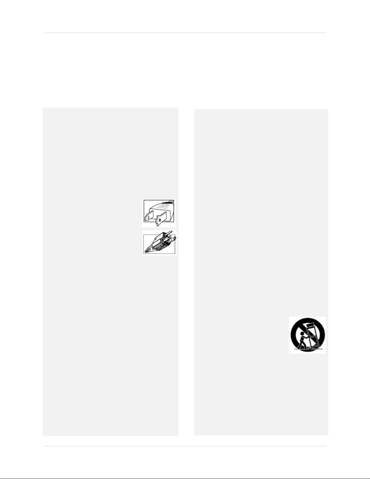
4. Polarization - Do not defeat the safety purpose of the
polarized or grounding-type plug.
A polarized plug has two blades with
one wider than the other.
A grounding type plug has two blades
and a third grounding prong.
The wide blade or the third prong are
provided for your safety.
If the provided plug does not fit into
your outlet, consult an electrician for
replacement of the obsolete outlet
5. Power Sources - This video product should be
operated only from the type of power source
indicated on the marking label. If you are not sure of
the type of power supply to your location, consult
your video dealer or local power company. For video
products intended to operate from battery power, or
other sources, refer to the operating instructions.
6. Overloading - Do not overload wall outlets of
extension cords as this can result in the risk of fire
or electric shock. Overloaded AC outlets, extension
cord s, fra yed po wer co rds, da mage d or cr acked wire
insulation, and broken plugs are dangerous. They
may result in a shock or fire hazard. Periodically
examine the cord, and if its appearance indicates
damage or deteriorated insulation, have it replaced
by your service technician.
7. Power-Cord Protection - Power supply cords should
be routed so that they are not likely to be walked on
or pinched by items placed upon or against them,
paying particular attention to cords at plugs,
convenience receptacles, and the point where they
exit from the video product.
8. Ventilation - Slots and openings in the case are
provided for ventilation to ensure reliable operation
of the video product and to protect it from
overheating. These openings must not be blocked or
covered. The openings should never be blocked by
placing the video equipment on a bed, sofa, rug, or
other similar surface. This video product should
never be placed near or over a radiator or heat
register. This video product should not be placed in
a built-in installation such as a bookcase or rack
unless proper ventilation is provided or the video
product manufacturer’s instructions have been
followed.
9. Attachments - Do not use attachments unless
recommended by the video product manufacturer as
they may cause a hazard.
10. Camera Extension Cables – Check the rating of your
extension cable(s) to verify compliance with your
local authority regulations prior to installation.
11. Water and Moisture - Do not use this video product
near water. For example, near a bath tub, wash bowl,
kitchen sink or laundry tub, in a wet basement, near
a swimming pool and the like.
Caution: Maintain electrical safety. Power line
operated equipment or accessories connected to
this unit should bear the UL listing mark of CSA
certification mark on the accessory itself and should
not be modified so as to defeat the safety features.
This will help avoid any potential hazard from
electrical shock or fire. If in doubt, contact qualified
service personnel.
12. Accessories - Do not place this
video equipment on an unstable
cart, stand, tripod, or table. The
video equipment may fall, causing
serious damage to the video
product. Use this video product
only with a cart, stand, tripod,
bracket, or table recommended by the manufacturer
or sold with the video product. Any mounting of the
product should follow the manufacturer’s
instructions and use a mounting accessory
recommended by the manufacturer.
vii
Page 8

Service
13. Servicing - Do not attempt to service this video
equipment yourself as opening or removing covers
may expose you to dangerous voltage or other
hazards. Refer all servicing to qualified service
personnel.
14. Conditions Requiring Service - Unplug this video
product from the wall outlet and refer servicing to
qualified service personnel under the following
conditions.
A. When the power supply cord or plug is
damaged.
B. If liquid has been spilled or objects have fallen
into the video product.
C. If the video product has been exposed to rain
or water.
D. If the video product does not operate normally
by following the operating instructions. Adjust
only those controls that are covered by the
operating instructions. Improper adjustment of
other controls may result in damage and will
often require extensive work by a qualified
technician to restore the video product to its
normal operation.
E. If the video product has been dropped or the
cabinet has been damaged.
Use
19. Cleaning - Unplug the video product from the wall
outlet before cleaning. Do not use liquid cleaners or
aerosol cleaners. Use a damp cloth for cleaning.
20. Product and Cart Combination - Video and cart
combination should be moved with care. Quick stops,
excessive force, and uneven surfaces may cause the
video product and car combination to overturn.
21. Object and Liquid Entry - Never push objects for any
kind into this video product through openings as they
may touch dangerous voltage points or “short-out”
parts that could result in a fire or electric shock.
Never spill liquid of any kind on the video product.
22. Lightning - For added protection for this video
product during a lightning storm, or when it is left
unattended and unused for long periods of time,
unplug it from the wall outlet and disconnect the
antenna or cable system. This will prevent damage
to the video product due to lightning and power line
surges.
F. When the video product exhibits a distinct
change in performance. This indicates a need for
service.
15. Replacement Parts - When replacement parts are
required, have the service technician verify that the
replacements used have the same safety
characteristics as the original parts. Use of
replacements specified by the video product
manufacturer can prevent fire, electric shock or
other hazards.
16. Safety Check - Upon completion of any service or
repairs to this video product, ask the service
technician to perform safety checks recommended
by the manufacturer to determine that the video
product is in safe operating condition.
17. Wall or Ceiling Mounting - The cameras provided
with this system should be mounted to a wall or
ceiling only as instructed in this guide, using the
provided mounting brackets.
18. Heat - The product should be situated away from
heat sources such as radiators, heat registers,
stoves, or other products (including amplifiers) that
produce heat.
viii
Page 9

General Precautions
FCC CLASS B NOTICE
Note
This equipment has been tested and found to comply with the limits for a Class B digital device, pursuant to
Part 15 of the FCC Rules. These limits are designed to provide reasonable protection against harmful
interference in a residential installation. This equipment generates, uses, and can radiate radio frequency
energy and, if not in-stalled and used in accordance with the instruction, may cause harmful interference to
radio communications.
However, there is no guarantee that interference will not occur in a particular installation. If this equipment
does cause harmful interference to radio or television reception (which can be determined by turning the
equipment on and off), the user is encouraged to try to correct the interference by one or more of the following
measures:
• Reorient or relocate the receiving antenna
• Increase the separation between the equipment and receiver
• Connect the equipment into an outlet on a circuit different from that to which the receiver is
connected
• Consult the dealer or an experienced radio or television technician for assistance
www.lorextechnology.com
1. All warnings and instructions in this manual should be followed.
2. Remove the plug from the outlet before cleaning. Do not use liquid aerosol detergents. Use a water dampened cloth for cleaning.
3. Do not use this unit in humid or wet places.
4. Keep enough space around the unit for ventilation. Slots and openings in the storage cabinet should not be blocked.
5. During lightning storms, or when the unit is not used for a long time, disconnect the power supply, antenna, and cables to protect the unit from electrical surge.
This equipment has been certified and found to comply with the limits regulated by FCC and EMC.
Therefore, it is designated to provide reasonable protection against interference and will not
cause interference with other appliance usage.
However, it is imperative that the user follows this manuals guideline to avoid improper usage
which may result in damage to the unit, electrical shock and fire hazard injury
In order to improve the feature functions and quality of this product, the specifications are subject
to change without notice from time to time.
ix
Page 10

1. Recording capacity may vary based on recording resolution & quality, lighting conditions and movement in the scene.
2. Easily mounts to the back of an LCD monitor with VESA standard mounting holes and an independent stand (monitor not included). Requires clear access to the 100 x100 mm VESA mounting holes.
3. DVI output only on 8/16-channel Edge models and 4/8/16 Edge+ models; VGA output only on 4-channel Edge and Edge mini models.
4. DVI to HDMI converter cable required (not included).
5. Not included in Edge mini.
6. Not included in Edge mini. Flex IR and remote control sold separately.
7. Instant Mobile Viewing on Blackberry™, iPhone™ or Windows Mobile™ 6.0 and above: selectable one channel live viewing.
Mobile phone data plan is required (not included). Router port forwarding required. For the latest smart phone compatibility
list, check www.lorextechnology.com
8. Requires a high speed internet connection and a router (not included).
System Features
• High performance network DVR
• H.264 compression for efficient storage and network speed
• EDGE design for standalone (vertical and horizontal) or VESA mount (Wall & LCD)
• Small form factor (Edge & Edge+ 11.6"x7.2"x1.7 ; Edge mini 7.3"x 7.7x 1.8)
• 3D graphics for sharp, color rich, high contrast video
• DVI/VGA output for display on PC monitor or TV with DVI/VGA input (DVI to VGA adapter included)
HDMI compatible
4
• Pentaplex operation - View, Record, Playback, Back Up & Remotely Control the system simultaneously
• View and record at VGA resolution: up to 640x480 per channel
• Video output (up to) 1280 x 1024 @ 60 Hz
• Supports up to 2TB SATA HDD
• USB mouse included, USB flash drive backup
1
2
3
,
• 2-channel audio
• 4/1 Alarm input/output
• "FLEX" IR extender (Remote control does not require line-of-sight)
5
6
• PTZ cameras supported , RS485 (included in Edge+ models only)
• Record on motion detection, schedule or continuous
• Internet Remote Functions: View, Search & Playback, Backup and Setup
• LOREX Instant Mobile Viewing on iPhone™, Blackberry™ Windows® Mobile and other
compatible 3G smart phones
• Exclusive LOREX Easy Connect Internet Set-up Wizard
7
8
• PC (Microsoft Windows™ 7/Vista/XP compatible) using Internet Explorer® browser
• Apple Mac compatible using the Safari browser for multi-channel live viewing
• Free LOREX DDNS (Dynamic Domain Name Service) for advanced remote connectivity at all times
• Email notification of events
x
Page 11

TABLE OF CONTENTS
Getting Started . . . . . . . . . . . . . . . . . . . . . . . . . . . . . . . . . . . . . . . . . . . . . . . . . 1
Lorex EDGE mini: Front Panel . . . . . . . . . . . . . . . . . . . . . . . . . . . . . . . . . . . . . . . . . . . . . 2
Lorex EDGE: Front Panel . . . . . . . . . . . . . . . . . . . . . . . . . . . . . . . . . . . . . . . . . . . . . . . . . . 3
Lorex EDGE: Rear Panel . . . . . . . . . . . . . . . . . . . . . . . . . . . . . . . . . . . . . . . . . . . . . . . . . . 3
Lorex EDGE+ : Front Panel . . . . . . . . . . . . . . . . . . . . . . . . . . . . . . . . . . . . . . . . . . . . . . . . 5
Lorex EDGE+: Rear Panel . . . . . . . . . . . . . . . . . . . . . . . . . . . . . . . . . . . . . . . . . . . . . . . . . 6
Basic Setup . . . . . . . . . . . . . . . . . . . . . . . . . . . . . . . . . . . . . . . . . . . . . . . . . . . . . . . . . . . . . 8
1. Mount the System . . . . . . . . . . . . . . . . . . . . . . . . . . . . . . . . . . . . . . . . . . . . . . . . . . . . . . . . . . . . . . . . . . . 8
2. Connect the Cameras . . . . . . . . . . . . . . . . . . . . . . . . . . . . . . . . . . . . . . . . . . . . . . . . . . . . . . . . . . . . . . . . 8
3. Connect the Monitor . . . . . . . . . . . . . . . . . . . . . . . . . . . . . . . . . . . . . . . . . . . . . . . . . . . . . . . . . . . . . . . . . 8
4. Connect the Ethernet cable . . . . . . . . . . . . . . . . . . . . . . . . . . . . . . . . . . . . . . . . . . . . . . . . . . . . . . . . . . . 8
5. Connect the Flex-IR Extender . . . . . . . . . . . . . . . . . . . . . . . . . . . . . . . . . . . . . . . . . . . . . . . . . . . . . . . . . 8
6. Connect the Power . . . . . . . . . . . . . . . . . . . . . . . . . . . . . . . . . . . . . . . . . . . . . . . . . . . . . . . . . . . . . . . . . . 8
System Passwords . . . . . . . . . . . . . . . . . . . . . . . . . . . . . . . . . . . . . . . . . . . . . . . . . . . . . . . 9
Mouse Control . . . . . . . . . . . . . . . . . . . . . . . . . . . . . . . . . . . . . . . . . . . . . . . . . . . . . . . . . . 9
Remote Control . . . . . . . . . . . . . . . . . . . . . . . . . . . . . . . . . . . . . . . . . . . . . . . . . . . . . . . . 10
Starting the System . . . . . . . . . . . . . . . . . . . . . . . . . . . . . . . . . . . . . . . . . . . . 11
Onscreen Display . . . . . . . . . . . . . . . . . . . . . . . . . . . . . . . . . . . . . . . . . . . . . . . . . . . . . . . 11
4-channel . . . . . . . . . . . . . . . . . . . . . . . . . . . . . . . . . . . . . . . . . . . . . . . . . . . . . . . . . . . . . . . . . . . . . . . . . . . . . . . . . . 11
8/16-channel . . . . . . . . . . . . . . . . . . . . . . . . . . . . . . . . . . . . . . . . . . . . . . . . . . . . . . . . . . . . . . . . . . . . . . . . . . . . . . . . 13
Using the Split-Screen Selector . . . . . . . . . . . . . . . . . . . . . . . . . . . . . . . . . . . . . . . . . . . 15
Live Viewing . . . . . . . . . . . . . . . . . . . . . . . . . . . . . . . . . . . . . . . . . . . . . . . . . . . . . . . . . . . . . . . . . . . . . . . . . 15
Playback . . . . . . . . . . . . . . . . . . . . . . . . . . . . . . . . . . . . . . . . . . . . . . . . . . . . . . . . . . . . . . . . . . . . . . . . . . . . 15
Flexible Camera Assignment . . . . . . . . . . . . . . . . . . . . . . . . . . . . . . . . . . . . . . . . . . . . . . . . . . . . . . . . . . . 16
Setting the Date and Time . . . . . . . . . . . . . . . . . . . . . . . . . . . . . . . . . . . . . . . 17
Recording. . . . . . . . . . . . . . . . . . . . . . . . . . . . . . . . . . . . . . . . . . . . . . . . . . . . . 18
Event Recording . . . . . . . . . . . . . . . . . . . . . . . . . . . . . . . . . . . . . . . . . . . . . . . . . . . . . . . . 18
Recording Audio . . . . . . . . . . . . . . . . . . . . . . . . . . . . . . . . . . . . . . . . . . . . . . . . . . . . . . . .18
Playback. . . . . . . . . . . . . . . . . . . . . . . . . . . . . . . . . . . . . . . . . . . . . . . . . . . . . . 19
Playback Markers . . . . . . . . . . . . . . . . . . . . . . . . . . . . . . . . . . . . . . . . . . . . . . . . . . . . . . 20
Additional Search Markers . . . . . . . . . . . . . . . . . . . . . . . . . . . . . . . . . . . . . . . . . . . . . . . . . . . . . . . . . . . . 20
Event List . . . . . . . . . . . . . . . . . . . . . . . . . . . . . . . . . . . . . . . . . . . . . . . . . . . . . 21
Channel Filter . . . . . . . . . . . . . . . . . . . . . . . . . . . . . . . . . . . . . . . . . . . . . . . . . . . . . . . . . . 21
Smart Search . . . . . . . . . . . . . . . . . . . . . . . . . . . . . . . . . . . . . . . . . . . . . . . . . . . . . . . . . .22
Event Details . . . . . . . . . . . . . . . . . . . . . . . . . . . . . . . . . . . . . . . . . . . . . . . . . . . . . . . . . . . 22
Searching for Recorded Data . . . . . . . . . . . . . . . . . . . . . . . . . . . . . . . . . . . . . . . . . . . . . 23
Live Mode . . . . . . . . . . . . . . . . . . . . . . . . . . . . . . . . . . . . . . . . . . . . . . . . . . . . . . . . . . . . . . . . . . . . . . . . . . . 23
xi
Page 12

Playback Mode . . . . . . . . . . . . . . . . . . . . . . . . . . . . . . . . . . . . . . . . . . . . . . . . . . . . . . . . . . . . . . . . . . . . . . 24
Taking Screenshots . . . . . . . . . . . . . . . . . . . . . . . . . . . . . . . . . . . . . . . . . . . . 25
Using Screenshots . . . . . . . . . . . . . . . . . . . . . . . . . . . . . . . . . . . . . . . . . . . . . . . . . . . . . . 26
Managing Passwords . . . . . . . . . . . . . . . . . . . . . . . . . . . . . . . . . . . . . . . . . . . 27
Using the Password Wheel . . . . . . . . . . . . . . . . . . . . . . . . . . . . . . . . . . . . . . . . . . . . . . . 27
Enabling and Disabling Passwords . . . . . . . . . . . . . . . . . . . . . . . . . . . . . . . . . . . . . . . . 27
Changing Passwords . . . . . . . . . . . . . . . . . . . . . . . . . . . . . . . . . . . . . . . . . . . . . . . . . . . . 28
Using the Main Menu . . . . . . . . . . . . . . . . . . . . . . . . . . . . . . . . . . . . . . . . . . . 29
Camera . . . . . . . . . . . . . . . . . . . . . . . . . . . . . . . . . . . . . . . . . . . . . . . . . . . . . . . . . . . . . . . 30
Setup . . . . . . . . . . . . . . . . . . . . . . . . . . . . . . . . . . . . . . . . . . . . . . . . . . . . . . . . . . . . . . . . . 30
Record . . . . . . . . . . . . . . . . . . . . . . . . . . . . . . . . . . . . . . . . . . . . . . . . . . . . . . . . . . . . . . . . 31
4-channel . . . . . . . . . . . . . . . . . . . . . . . . . . . . . . . . . . . . . . . . . . . . . . . . . . . . . . . . . . . . . . . . . . . . . . . . . . . . . . . . . . 31
8/16-channel . . . . . . . . . . . . . . . . . . . . . . . . . . . . . . . . . . . . . . . . . . . . . . . . . . . . . . . . . . . . . . . . . . . . . . . . . . . . . . . . 32
Schedule . . . . . . . . . . . . . . . . . . . . . . . . . . . . . . . . . . . . . . . . . . . . . . . . . . . . . . . . . . . . . . . . . . . . . . . . . . . 33
4/8/16-channel . . . . . . . . . . . . . . . . . . . . . . . . . . . . . . . . . . . . . . . . . . . . . . . . . . . . . . . . . . . . . . . . . . . . . . . . . . . . . .33
Format HDD . . . . . . . . . . . . . . . . . . . . . . . . . . . . . . . . . . . . . . . . . . . . . . . . . . . . . . . . . . . . . . . . . . . . . . . . . 34
Storage Calculator . . . . . . . . . . . . . . . . . . . . . . . . . . . . . . . . . . . . . . . . . . . . . . . . . . . . . . . . . . . . . . . . . . . . . . . . . . .34
Alarm . . . . . . . . . . . . . . . . . . . . . . . . . . . . . . . . . . . . . . . . . . . . . . . . . . . . . . . . . . . . . . . . . 34
4-channel . . . . . . . . . . . . . . . . . . . . . . . . . . . . . . . . . . . . . . . . . . . . . . . . . . . . . . . . . . . . . . . . . . . . . . . . . . . . . . . . . . 34
8/16-channel . . . . . . . . . . . . . . . . . . . . . . . . . . . . . . . . . . . . . . . . . . . . . . . . . . . . . . . . . . . . . . . . . . . . . . . . . . . . . . . . 36
Motion . . . . . . . . . . . . . . . . . . . . . . . . . . . . . . . . . . . . . . . . . . . . . . . . . . . . . . . . . . . . . . . . . . . . . . . . . . . . . 37
4/8/16-channel . . . . . . . . . . . . . . . . . . . . . . . . . . . . . . . . . . . . . . . . . . . . . . . . . . . . . . . . . . . . . . . . . . . . . . . . . . . . . .37
Backup . . . . . . . . . . . . . . . . . . . . . . . . . . . . . . . . . . . . . . . . . . . . . . . . . . . . . . . . . . . . . . . . 38
Formatting the USB Drive . . . . . . . . . . . . . . . . . . . . . . . . . . . . . . . . . . . . . . . . . . . . . . . . . . . . . . . . . . . . . 38
Confirming Backup . . . . . . . . . . . . . . . . . . . . . . . . . . . . . . . . . . . . . . . . . . . . . . . . . . . . . . . . . . . . . . . . . . . . . . . . . . . 39
Backup File Information . . . . . . . . . . . . . . . . . . . . . . . . . . . . . . . . . . . . . . . . . . . . . . . . . . . . . . . . . . . . . . . . . . . . . . . 39
Setting Quicktime as a default media player . . . . . . . . . . . . . . . . . . . . . . . . . . . . . . . . . . . . . . . . . . . . . . . . . . . . . . 39
LAN . . . . . . . . . . . . . . . . . . . . . . . . . . . . . . . . . . . . . . . . . . . . . . . . . . . . . . . . . . . . . . . . . . 40
Easy Connect . . . . . . . . . . . . . . . . . . . . . . . . . . . . . . . . . . . . . . . . . . . . . . . . . . . . . . . . . . . . . . . . . . . . . . . . 40
LAN Password . . . . . . . . . . . . . . . . . . . . . . . . . . . . . . . . . . . . . . . . . . . . . . . . . . . . . . . . . . . . . . . . . . . . . . . 41
Upgrading Firmware . . . . . . . . . . . . . . . . . . . . . . . . . . . . . . . . . . . . . . . . . . . . . . . . . . . . . . . . . . . . . . . . . . 41
Changing Ports On Your System. . . . . . . . . . . . . . . . . . . . . . . . . . . . . . . . . . 42
REMOTE ACCESS: DVR Netviewer . . . . . . . . . . . . . . . . . . . . . . . . . . . . . . . . 46
System Requirements . . . . . . . . . . . . . . . . . . . . . . . . . . . . . . . . . . . . . . . . . . . . . . . . . . . 46
Netviewer: Basic Layout . . . . . . . . . . . . . . . . . . . . . . . . . . . . . . . . . . . . . . . . . . . . . . . . . 47
Network User Profiles . . . . . . . . . . . . . . . . . . . . . . . . . . . . . . . . . . . . . . . . . . . . . . . . . . . 47
DVR Netviewer Main Screen . . . . . . . . . . . . . . . . . . . . . . . . . . . . . . . . . . . . . . . . . . . . . . 48
4-channel . . . . . . . . . . . . . . . . . . . . . . . . . . . . . . . . . . . . . . . . . . . . . . . . . . . . . . . . . . . . . . . . . . . . . . . . . . . . . . . . . . 48
8/16-channel . . . . . . . . . . . . . . . . . . . . . . . . . . . . . . . . . . . . . . . . . . . . . . . . . . . . . . . . . . . . . . . . . . . . . . . . . . . . . . . . 49
Live Viewing . . . . . . . . . . . . . . . . . . . . . . . . . . . . . . . . . . . . . . . . . . . . . . . . . . . . . . . . . . .50
Playback . . . . . . . . . . . . . . . . . . . . . . . . . . . . . . . . . . . . . . . . . . . . . . . . . . . . . . . . . . . . . . 50
Using the Pop-Up Calendar . . . . . . . . . . . . . . . . . . . . . . . . . . . . . . . . . . . . . . . . . . . . . . . 50
Backup . . . . . . . . . . . . . . . . . . . . . . . . . . . . . . . . . . . . . . . . . . . . . . . . . . . . . . . . . . . . . . . . 51
Setup . . . . . . . . . . . . . . . . . . . . . . . . . . . . . . . . . . . . . . . . . . . . . . . . . . . . . . . . . . . . . . . . . 52
xii
Page 13

Bitrate . . . . . . . . . . . . . . . . . . . . . . . . . . . . . . . . . . . . . . . . . . . . . . . . . . . . . . . . . . . . . . . . . . . . . . . . . . . . . 52
PPPoE . . . . . . . . . . . . . . . . . . . . . . . . . . . . . . . . . . . . . . . . . . . . . . . . . . . . . . . . . . . . . . . . . . . . . . . . . . . . . 52
DDNS . . . . . . . . . . . . . . . . . . . . . . . . . . . . . . . . . . . . . . . . . . . . . . . . . . . . . . . . . . . . . . . . . . . . . . . . . . . . . . 52
System Status . . . . . . . . . . . . . . . . . . . . . . . . . . . . . . . . . . . . . . . . . . . . . . . . . . . . . . . . . . . . . . . . . . . . . . . 53
Resuming Live Viewing . . . . . . . . . . . . . . . . . . . . . . . . . . . . . . . . . . . . . . . . . . . . . . . . . . . . . . . . . . . . . . . . 53
Mail . . . . . . . . . . . . . . . . . . . . . . . . . . . . . . . . . . . . . . . . . . . . . . . . . . . . . . . . . . . . . . . . . . . . . . . . . . . . . . . . 54
Title . . . . . . . . . . . . . . . . . . . . . . . . . . . . . . . . . . . . . . . . . . . . . . . . . . . . . . . . . . . . . . . . . . . . . . . . . . . . . . . 54
Setting up Local and Remote Viewing . . . . . . . . . . . . . . . . . . . . . . . . . . . . . 55
What do I need? . . . . . . . . . . . . . . . . . . . . . . . . . . . . . . . . . . . . . . . . . . . . . . . . . . . . . . . . . . . . . . . . . . . . . . 55
Viewing your system through a Local Area Network . . . . . . . . . . . . . . . . . . . . . . . . . . 56
Finding your IP address and port number . . . . . . . . . . . . . . . . . . . . . . . . . . . . . . . . . . . . . . . . . . . . . . . . . . . . . . . 56
Connecting to your system . . . . . . . . . . . . . . . . . . . . . . . . . . . . . . . . . . . . . . . . . . . . . . . . . . . . . . . . . . . . . 57
Connecting to your system on Internet Explorer (PC): . . . . . . . . . . . . . . . . . . . . . . . . . . . . . . . . . . . . . . 57
Connecting to the system using Safari (Mac) . . . . . . . . . . . . . . . . . . . . . . . . . . . . . . . . . . . . . . . . . . . . . . 58
Setting Up Remote Connectivity . . . . . . . . . . . . . . . . . . . . . . . . . . . . . . . . . . 60
Remote Connectivity Options . . . . . . . . . . . . . . . . . . . . . . . . . . . . . . . . . . . . . . . . . . . . . . . . . . . . . . . . . . . 60
Remote Viewing Using Easy Connect . . . . . . . . . . . . . . . . . . . . . . . . . . . . . . 61
Before You Get Started . . . . . . . . . . . . . . . . . . . . . . . . . . . . . . . . . . . . . . . . . . . . . . . . . . 61
Enabling Easy Connect . . . . . . . . . . . . . . . . . . . . . . . . . . . . . . . . . . . . . . . . . . . . . . . . . . 62
Upgrading The Firmware . . . . . . . . . . . . . . . . . . . . . . . . . . . . . . . . . . . . . . . . . . . . . . . . 62
Prep the USB Flash Drive . . . . . . . . . . . . . . . . . . . . . . . . . . . . . . . . . . . . . . . . . . . . . . . . . . . . . . . . . . . . . . . . . . . . .62
Download the firmware from the Lorex website . . . . . . . . . . . . . . . . . . . . . . . . . . . . . . . . . . . . . . . . . . . . . . . . . . .63
Upgrade the DVR firmware . . . . . . . . . . . . . . . . . . . . . . . . . . . . . . . . . . . . . . . . . . . . . . . . . . . . . . . . . . . . . . . . . . . . 63
Enabling Easy Connect on your DVR . . . . . . . . . . . . . . . . . . . . . . . . . . . . . . . . . . . . . . . 63
Registering for an Easy Connect account . . . . . . . . . . . . . . . . . . . . . . . . . . . . . . . . . . . 64
Connecting to your DVR using Easy Connect . . . . . . . . . . . . . . . . . . . . . . . . . . . . . . . . . 66
How port forwarding works . . . . . . . . . . . . . . . . . . . . . . . . . . . . . . . . . . . . . . . . . . . . . . 68
Lorex Auto Port Forwarding Wizard . . . . . . . . . . . . . . . . . . . . . . . . . . . . . . 69
Installation . . . . . . . . . . . . . . . . . . . . . . . . . . . . . . . . . . . . . . . . . . . . . . . . . . . . . . . . . . . . 69
Obtaining Your Router Model Number and Version . . . . . . . . . . . . . . . . . . . . . . . . . . . . . . . . . . . . . . . . . . . . . . . .70
Example . . . . . . . . . . . . . . . . . . . . . . . . . . . . . . . . . . . . . . . . . . . . . . . . . . . . . . . . . . . . . . . . . . . . . . . . . . . . . . . . . . . .70
Configuration . . . . . . . . . . . . . . . . . . . . . . . . . . . . . . . . . . . . . . . . . . . . . . . . . . . . . . . . . . 71
Initial Startup: Select language . . . . . . . . . . . . . . . . . . . . . . . . . . . . . . . . . . . . . . . . . . . . . . . . . . . . . . . . . . . . . . . . .71
Step 1: Populate the router database . . . . . . . . . . . . . . . . . . . . . . . . . . . . . . . . . . . . . . . . . . . . . . . . . . . . . . . . . . . .71
Step 2: Enter your router settings . . . . . . . . . . . . . . . . . . . . . . . . . . . . . . . . . . . . . . . . . . . . . . . . . . . . . . . . . . . . . . . 72
Step 3: Update the router settings . . . . . . . . . . . . . . . . . . . . . . . . . . . . . . . . . . . . . . . . . . . . . . . . . . . . . . . . . . . . . . 73
Step 4: Test your connection . . . . . . . . . . . . . . . . . . . . . . . . . . . . . . . . . . . . . . . . . . . . . . . . . . . . . . . . . . . . . . . . . . . 73
Configuring multiple routers . . . . . . . . . . . . . . . . . . . . . . . . . . . . . . . . . . . . . . . . . . . . . . . . . . . . . . . . . . . . . . . . . . . 73
Scenario A: Router/Modem combination + Router . . . . . . . . . . . . . . . . . . . . . . . . . . . . . . . . . . . . . . . . . . . . . . . . . 74
Scearnio B: Multiple Routers . . . . . . . . . . . . . . . . . . . . . . . . . . . . . . . . . . . . . . . . . . . . . . . . . . . . . . . . . . . . . . . . . . 74
Example . . . . . . . . . . . . . . . . . . . . . . . . . . . . . . . . . . . . . . . . . . . . . . . . . . . . . . . . . . . . . . . . . . . . . . . . . . . . . . . . . . . .75
Setting Up DDNS . . . . . . . . . . . . . . . . . . . . . . . . . . . . . . . . . . . . . . . . . . . . . . . . . . . . . . . . 76
Enabling DDNS on your system . . . . . . . . . . . . . . . . . . . . . . . . . . . . . . . . . . . . . . . . . . . 77
Networking Checklist . . . . . . . . . . . . . . . . . . . . . . . . . . . . . . . . . . . . . . . . . . . . . . . . . . . 78
Mobile Connectivity . . . . . . . . . . . . . . . . . . . . . . . . . . . . . . . . . . . . . . . . . . . . 80
xiii
Page 14

Compatible Mobile Viewing Devices . . . . . . . . . . . . . . . . . . . . . . . . . . . . . . . . . . . . . . . . . . . . . . . . . . . . . . . . . . . . . 80
Before You Begin . . . . . . . . . . . . . . . . . . . . . . . . . . . . . . . . . . . . . . . . . . . . . . . . . . . . . . . . . 80
Mobile Connectivity on the iPhone / iPad . . . . . . . . . . . . . . . . . . . . . . . . . . . . . . . . . . . 81
iPhone Users . . . . . . . . . . . . . . . . . . . . . . . . . . . . . . . . . . . . . . . . . . . . . . . . . . . . . . . . . . . . . . . . . . . . . . . . . . . . . . . 81
Downloading the Lorex Live Application . . . . . . . . . . . . . . . . . . . . . . . . . . . . . . . . . . . . . . . . . . . . . . . . . . . . . . . . . 81
Connecting To Your DVR - iPhone Users . . . . . . . . . . . . . . . . . . . . . . . . . . . . . . . . . . . . . . . . . . . . . . . . . . . . . . . . . 81
The Lorex Live Interface . . . . . . . . . . . . . . . . . . . . . . . . . . . . . . . . . . . . . . . . . . . . . . . . . . . . . . . . . . . . . . . . . . . . . . 82
Connecting To Your DVR - iPad users . . . . . . . . . . . . . . . . . . . . . . . . . . . . . . . . . . . . . . 83
Mobile Connectivity on Windows Mobile . . . . . . . . . . . . . . . . . . . . . . . . . . . . . . . . . . . . 84
Connecting to your DVR using Mobile View . . . . . . . . . . . . . . . . . . . . . . . . . . . . . . . . . . . . . . . . . . . . . . . . . . . . . . . 84
Mobile Connectivity on the Blackberry . . . . . . . . . . . . . . . . . . . . . . . . . . . . . . . . . . . . . 85
Appendix A: System Specifications . . . . . . . . . . . . . . . . . . . . . . . . . . . . . . . 89
EDGE SERIES DVR . . . . . . . . . . . . . . . . . . . . . . . . . . . . . . . . . . . . . . . . . . . . . . . . . . . . . . 89
Appendix A: System Specifications (cont’d.) . . . . . . . . . . . . . . . . . . . . . . . . . . . . . . . . . 90
EDGE SERIES DVR . . . . . . . . . . . . . . . . . . . . . . . . . . . . . . . . . . . . . . . . . . . . . . . . . . . . . . 90
Product Information . . . . . . . . . . . . . . . . . . . . . . . . . . . . . . . . . . . . . . . . . . . . . . . . . . . . . 90
Edge+and Edge Mini Specifications . . . . . . . . . . . . . . . . . . . . . . . . . . . . . . . . . . . . . . . . 91
Appendix B: Connecting Motion / Alarm Devices . . . . . . . . . . . . . . . . . . . . 94
PTZ Control Interface . . . . . . . . . . . . . . . . . . . . . . . . . . . . . . . . . . . . . . . . . . . . . . . . . . . . . . . . . . . . . . . . . . . . . . . . .97
Appendix C: Connecting Audio . . . . . . . . . . . . . . . . . . . . . . . . . . . . . . . . . . . 99
Appendix D: Full Connectivity Diagram . . . . . . . . . . . . . . . . . . . . . . . . . . . 101
Appendix E: Replacing the Hard Drive . . . . . . . . . . . . . . . . . . . . . . . . . . . . 104
EDGE Series DVR . . . . . . . . . . . . . . . . . . . . . . . . . . . . . . . . . . . . . . . . . . . . . . . . . . . . . . . . . . . . . . . . . . . 104
EDGE+ DVR . . . . . . . . . . . . . . . . . . . . . . . . . . . . . . . . . . . . . . . . . . . . . . . . . . . . . . . . . . . 106
Formatting the Hard Drive . . . . . . . . . . . . . . . . . . . . . . . . . . . . . . . . . . . . . . . . . . . . . .110
Troubleshooting . . . . . . . . . . . . . . . . . . . . . . . . . . . . . . . . . . . . . . . . . . . . . . 111
xiv
Page 15
GETTING STARTED
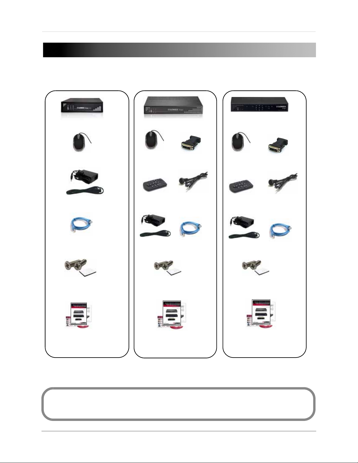
EDGE DVR (LH310)
EDGE+ DVR (LH320)
USB Mouse
Power Adapter
Mounting Kit
(Mounting Kit contents
may differ from image)
Ethernet Cable
Instruction manual, quickstart
guide, documentation CD
Flex IR & remote control sold separately
Remote Control
USB Mouse
DVI / VGA Adapter
(8 & 16 channel
models only)
Flex-IR Extender
Power Adapter
Mounting Kit
(Mounting Kit contents
may differ from image)
Ethernet Cable
Instruction manual, quickstart
guide, documentation CD
Remote Control
DVI / VGA Adapter
USB Mouse
Flex-IR Extender
Power Adapter
Mounting Kit
(Mounting Kit contents
may differ from image)
Ethernet Cable
Instruction manual, quickstart
guide, documentation CD
EDGE mini DVR (LH304)
The system comes with the following components:
DVR MODEL, HARD DRIVE SIZE, NUMBER OF CHANNELS, AND CAMERA CONFIGURATION MAY
VARY BY MODEL. PLEASE REFER TO YOUR PACKAGE FOR SPECIFIC DETAILS.
CHECK YOUR PACKAGE TO CONFIRM THAT YOU HAVE RECEIVED THE COMPLETE SYSTEM,
INCLUDING ALL COMPONENTS SHOWN ABOVE.
1
Page 16
Getting Started
3
1
2
3
1 2
4
7
5
8
6
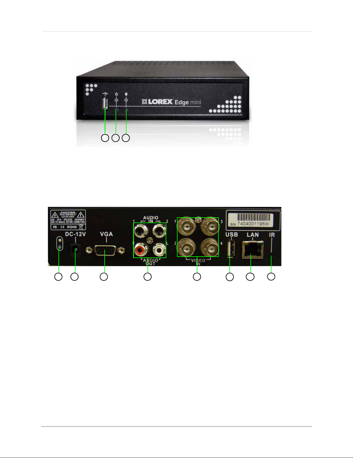
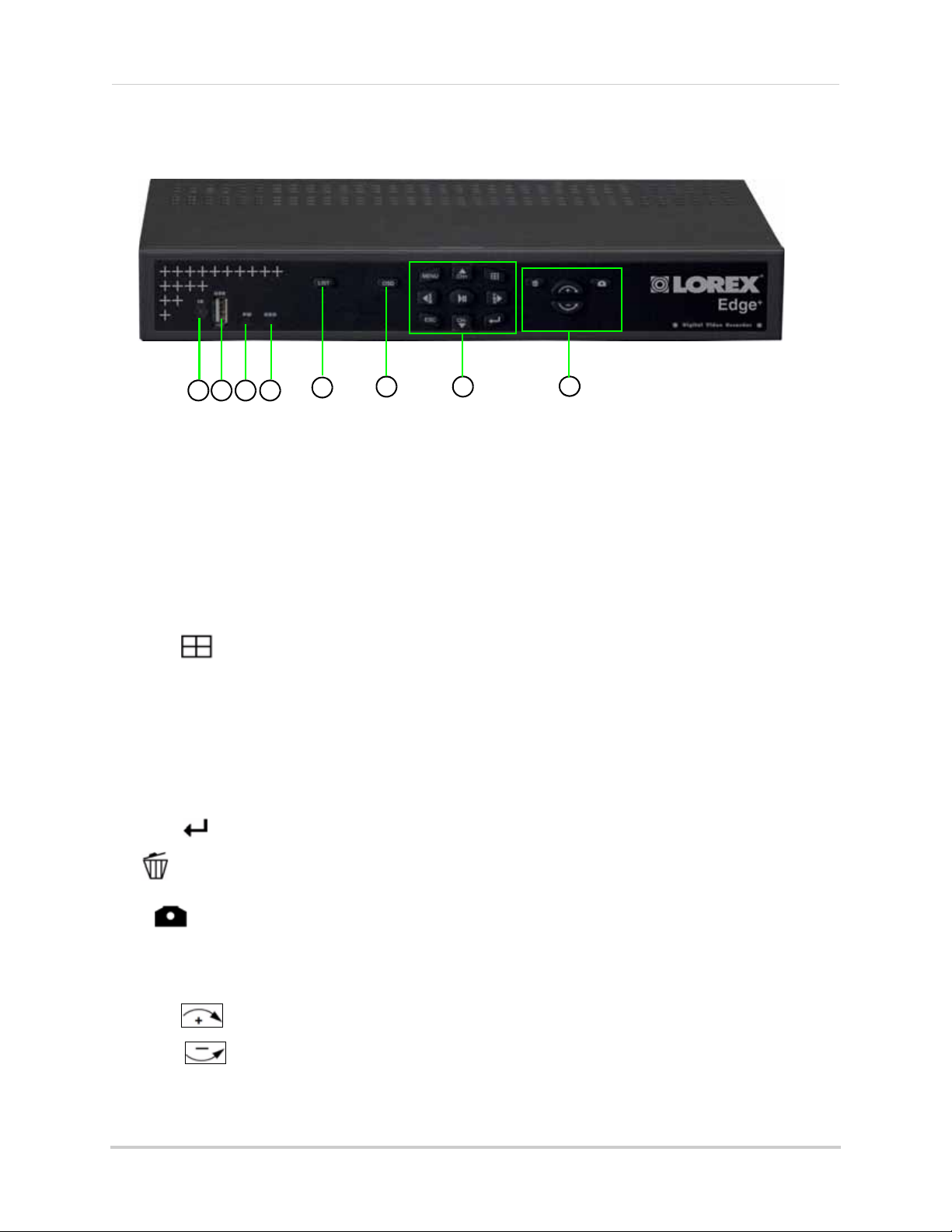
Lorex EDGE mini: Front Panel
1. USB port: Connect a USB flash drive for data backup and firmware updates (download from website).
2. Power Indicator: LED indicator for system power.
3. HDD Indicator: LED indicator for internal hard drive.
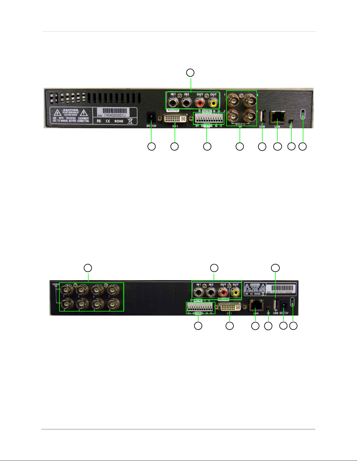
Lorex EDGE mini: Rear Panel
1. GND: Ground port.
2. DC 12V: Port for 12V DC, 2.5A power adapter (included).
3. VGA: Port to connect a VGA monitor (not included).
4. Audio In: Input ports for audio enabled cameras. Audio Out: Output for two audio channels.
5. Video In: BNC input ports for 4 BNC cameras.
6. USB Port: Port for a USB mouse.
7. LAN: Networking port for a 10/100 Base-T RJ-45 network cable (included).
8. Flex IR port :Port for the Flex-IR Extender (Flex-IR Extender optional, not included).
11
2
Page 17
Getting Started
1
2
3
4
1
2
3
6
7
8
9
4
5
10
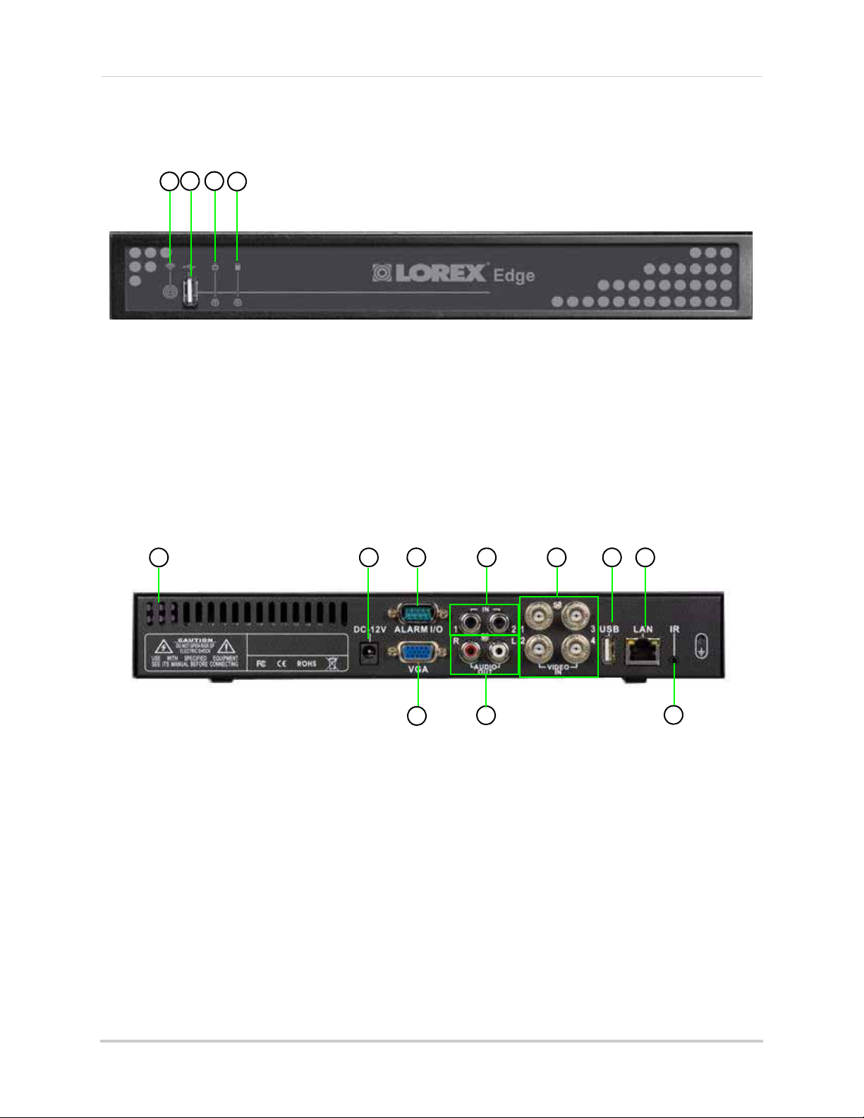
Lorex EDGE: Front Panel
All models
1. IR Receiver: Internal IR receiver for the remote control.
2. USB port: Connect a USB flash drive for data backup and firmware updates (download from website).
3. Power Indicator: LED indicator for system power. When system is powered on, LED is lit red.
4. HDD Indicator: LED indicator for internal hard drive. When in continuous recording mode, LED pulses red.
Lorex EDGE: Rear Panel
4-channel models
1. Exhaust slots: Slots to let heat escape from the internal hard drive.
proper ventilation.
2. DC 12V: Port for 12V DC 2.5 A power adapter (included).
3. Alarm I/O: Input/output port for alarm / relay (D-sub 9 connector required—not included).
4. Audio In: Input ports for audio enabled cameras.
5. Video In: BNC input ports for 4 BNC cameras.
6. USB Port: Port for a USB mouse.
7. LAN: Networking port for a 10/100 Base-T RJ-45 network cable (included).
8. VGA: Port to connect a VGA monitor (not included)
9. Audio Out: Output for two audio channels.
10. IR: Port for the Flex-IR Extender.
11. Ground Port
Do not block
. Allow for
3
Page 18
Getting Started
3
4
1 2
8
5
6
7
9
10
5
8
3
1 2
4
6
10
7
94
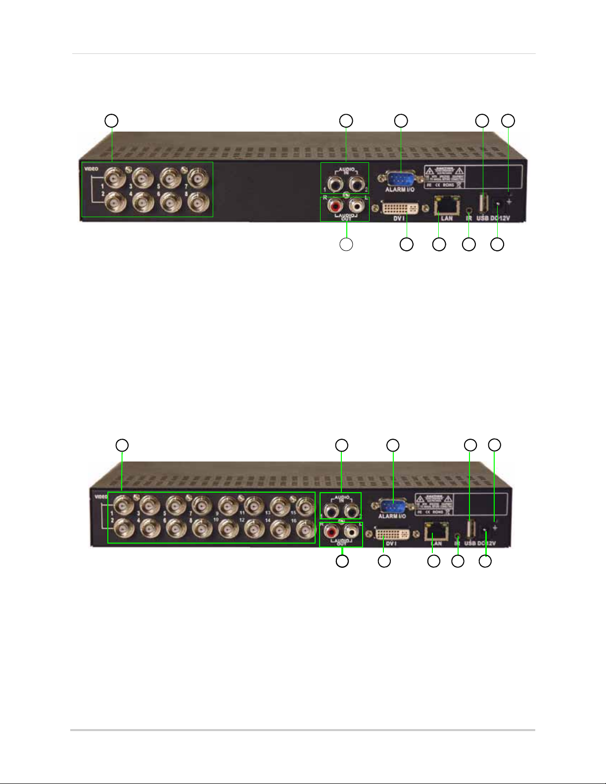
Lorex EDGE: Rear Panel
8-channel
1. Video In: BNC input ports for 8 BNC cameras.
2. Audio In: Input ports for audio enabled cameras.
3. Alarm I/O: Input/output port for alarm / relay (D-sub 9 connector required—not included).
4. Audio Out: Output for two audio channels.
5. DVI: Port to connect a DVI monitor (not included).
6. LAN: Networking port for a 10/100 Base-T RJ-45 network cable (included).
7. IR: Port for the Flex-IR Extender.
8. USB Port: Port for a USB mouse.
9. DC 12V: Port for 12V DC 3 A power adapter (included).
10. Ground Port.
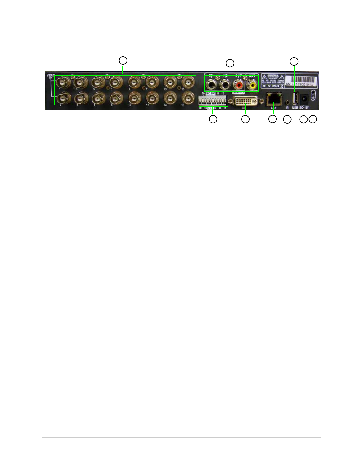
16-channel
1. Video In: BNC input ports for 16 BNC cameras.
2. Audio In: Input ports for audio enabled cameras.
3. Alarm I/O: Input/output port for alarm / relay (D-sub 9 connector required—not included).
4. Audio Out: Output for two audio channels.
5. DVI: Port to connect a DVI monitor (not included).
6. LAN: Networking port for a 10/100 Base-T RJ-45 network cable (included).
7. IR: Port for the Flex-IR Extender.
8. USB Port: Port for a USB mouse.
9. DC 12V: Port for 12V DC 3 A power adapter (included).
10. Ground Port.
4
Page 19
Getting Started
5
8
3
1 2
4
6
7
Lorex EDGE+ : Front Panel
All Models
1. IR Receiver: Internal IR receiver for the remote control.
2. USB port: Connect a USB flash drive for data backup and firmware updates (download from website).
3. Power Indicator: LED indicator for system power. When system is powered on, LED is lit red.
4. HDD Indicator: LED indicator for internal hard drive. When in continuous recording mode, LED pulses red.
5. LIST: Opens the Event List menu.
6. OSD: Show/hide the on-screen display.
7. Primary Controls:
• MENU: Opens the system main menu.
• : Press to open the Split-Screen Selection menu (
From full-screen single channel view, changes display view to Quad split-screen (
• S/CH+: Move cursor in menus up; Channel Up.
• X/FWD: Move cursor in menus right; during playback, increase forward playback speed (5X, 15X, 60X).
• W/REW: Move cursor in menus left; during playback, increase reverse playback speed (5X, 15X, 60X)
• /: Start/pause forward playback.
• T/CH-: Move cursor in menus down; Channel down.
• ESC: Go back / exit menus.
8 / 16-channel only
).
4-channel model only
• : Confirm menu selections. Press twice in live viewing to access system information.
8. : While in Event List menu, press to delete a selected event (no confirm or undo).
• : During Live Mode and Playback; Press to take a screenshot of the main display—USB
flash drive must be connected
(8/16-channel only).
• Increase/Decrease buttons:
• : Increase the value of selected menu option.
• : Decrease the value of selected menu option.
)
5
Page 20
Getting Started
5
8
3
1 2
4
6 7
9
5
8
3
1 2
4
6
7
9
Lorex EDGE+: Rear Panel
4-channel
1. DC 12V: Port for 12V DC, 2.5A power adapter (included).
2. DVI: Port to connect a DVI monitor (not included).
3. Audio In: Input ports for audio enabled cameras. Audio Out: Output for two audio channels.
4. Alarm Block: Input/output port for alarm / relay devices (i.e. PTZ cameras and sensors, not included).
5. Video In: BNC input ports for BNC cameras.
6. USB Port: Port for a USB mouse.
7. LAN: Networking port for a 10/100 Base-T RJ-45 network cable (included).
8. IR: Port for the Flex-IR Extender.
9. Ground Port.
8-channel
1. Video In: BNC input ports for BNC cameras.
2. Audio In: Input ports for audio enabled cameras (not included). Audio Out: Output for two audio channels.
3. Alarm Block: Input/output port for alarm / relay devices (i.e. PTZ cameras and sensors, not included).
4. DVI: Port to connect a DVI monitor (not included).
5. LAN: Networking port for a 10/100 Base-T RJ-45 network cable (included).
6. IR: Port for the Flex-IR Extender.
7. USB Port: Port for a USB mouse.
8. DC 12V: Port for 12V DC, 3A power adapter (included).
9. Ground Port.
6
Page 21
Getting Started
5
8
3
1
2
4
6
7
9
16-channel
1. Video In: BNC input ports for 16 BNC cameras.
2. Audio In: Input ports for audio enabled cameras (not included). Audio Out: Output for two audio channels.
3. Alarm Block: Input/output port for alarm / relay devices (i.e. PTZ cameras and sensors, not included).
4. DVI: Port to connect a DVI monitor (not included).
5. LAN: Networking port for a 10/100 Base-T RJ-45 network cable (included).
6. IR: Port for the Flex-IR Extender.
7. USB Port: Port for a USB mouse.
8. DC 12V: Port for 12V DC, 3A power adapter (included).
9. Ground Port.
7
Page 22
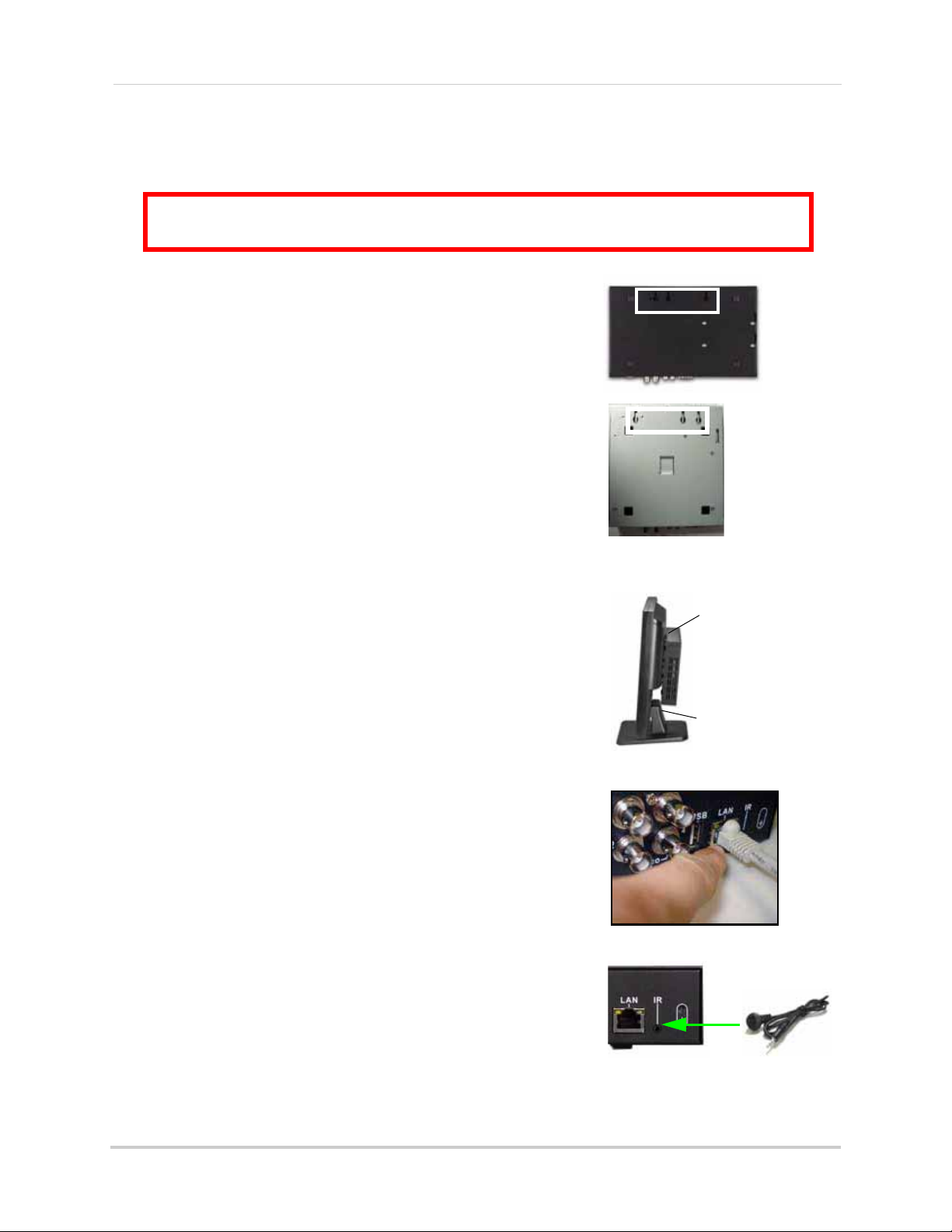
Getting Started
ATTENTION: You can only mount the system to an LCD monitor that has a VESA mount
and an independent stand, with clear access to the VESA mount holes.
Figure 1.3 Connect the Flex IR extender (Available as an optional accessory for the EDGE mini)
Figure 1.1 Mount the system to the
monitor
Figure 1.2 Connect the Ethernet cable
Figure 1.0 Mounting holes on bottom panel
VESA
mount
Independe
nt stand
EDGE & EDGE
+
EDGE mini
Basic Setup
The system is designed to mount to the back of most LCD monitors with a VESA mount. If desired,
you can mount it to a wall or leave the system in a standard horizontal or vertical position.
1. Mount the System
a. Screw the provided mounting screws into the two top
holes in the rear panel of your LCD monitor. Make sure
the screws are only 3/4 of the way in; this will allow
sufficient clearance to hang the system.
b. Carefully place the system (front panel facing up) over
the screws and slide down into place.
2. Connect the Cameras
panel.
3. Connect the Monitor
a. Connect BNC cameras to the BNC ports on the rear
a. Connect the VGA / DVI cable (not included) from your LCD
monitor to the VGA or DVI port on the rear panel of the
system.
4. Connect the Ethernet cable
a. Connect the included Ethernet cable to the LAN port on
the rear panel of system; connect the other end of the
Ethernet cable to an empty LAN port on your router (not
included).
5. Connect the Flex-IR Extender
a. Connect the Flex-IR extender to the port on the rear
panel of the DVR. Position the Flex-IR extender near the
front of your monitor, or where it will receive a clear
signal from the remote control. Use a piece of
double-sided tape (included) to help secure the Flex-IR
Extender.
NOTE: The Flex-IR Extender is not required for normal operation.
It may be necessary if there is not a clear line-of-sight between the
DVR and the remote control.The Edge mini has an optional Flex IR
extender and remote control.
6. Connect the Power
a. Connect the power cord to the DC12V port in the rear
panel of the system.
8
Page 23
Getting Started
LEVEL ID PASSWORD
USER 1 1111
ADMIN 2 2222
LEVEL ID PASSWORD
USER 2 2222
ADMIN 3 3333
LEVEL ID PASSWORD
GUEST 7 1111
USER 8 2222
ADMIN 9 3333
8 & 16 Channel
4/ 8/ 16 Channel
4 Channel
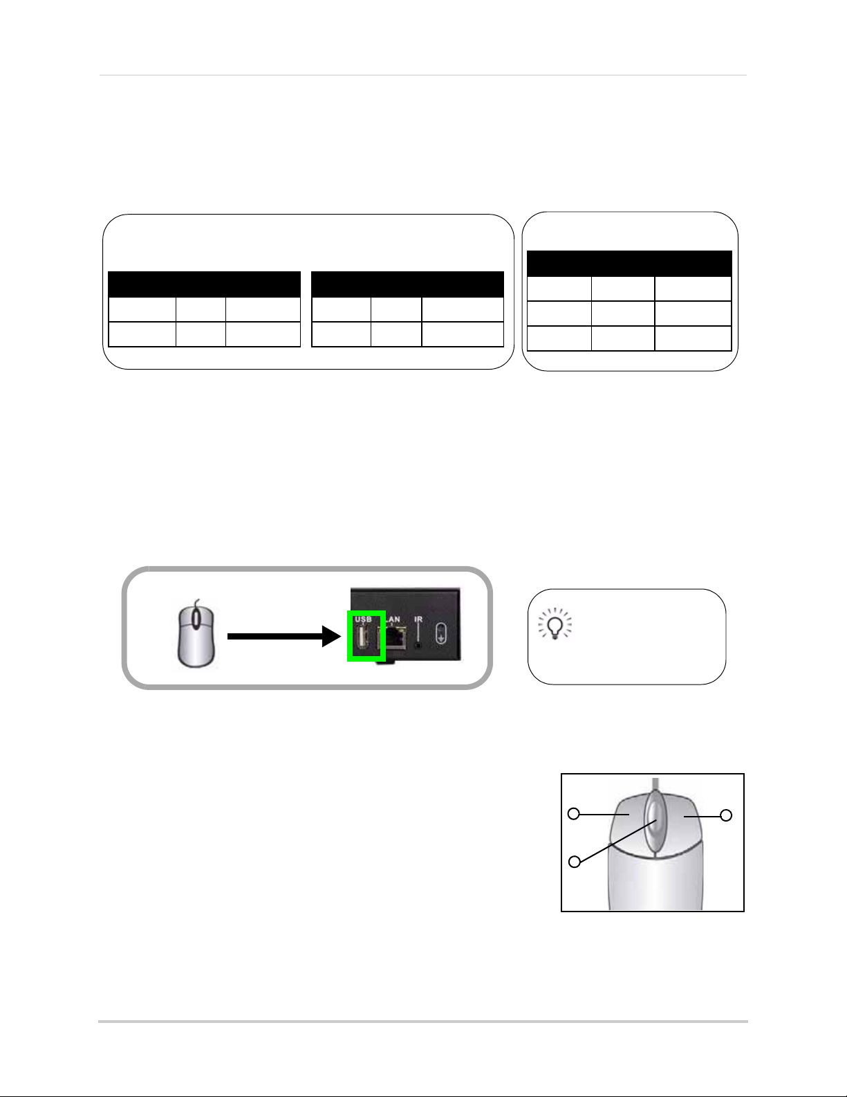
Local DVR Access
Remote/LAN Viewing
Figure 2.0 Connect a USB mouse to the USB port on the rear panel
Tip!
Connect the mouse to the
USB port on the rear panel
to allow for easy access of
a USB backup device using
the front panel.
1
2
3
Figure 2.1 Mouse button operation
System Passwords
Depending on your system model, the default user name (ID) and password is different. Refer to
the tables below for details on the default system user IDs and passwords.
Mouse Control
The mouse is the primary input device for navigating system menus.
NOTE: Unless otherwise noted, all system functions described in this manual are achieved through
mouse input.
To use a mouse with the system:
1. Connect a USB mouse to the USB port on rear panel of the system.
2. Use the mouse buttons to perform the following:
• Left-Button: Click to select a menu option; while in
Split-Screen mode (Live View or Playback), click on a channel
to view the selected channel in full-screen.
• Right-Button: Click to return to previous menu; exit menus/
modes.
3. Scroll-Wheel: Scroll up/down to change values in selected menu options; position markers in playback bar.
9
Page 24
Getting Started
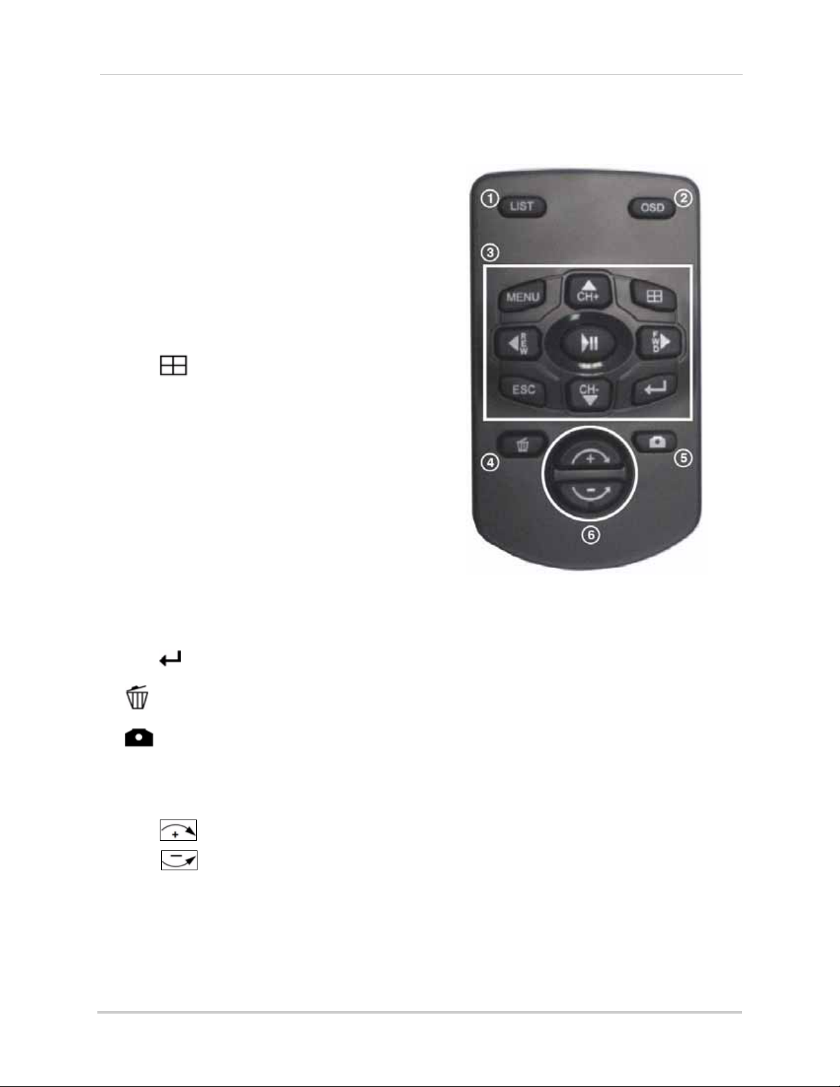
Figure 3.0 Remote Control
Remote Control
The remote control is the secondary input device
for navigating the system’s graphical user
interface.
To use the remote control:
1. LIST: Open the Event List menu.
2. OSD: Show/hide the on-screen display.
3. Primary controls:
• MENU: Opens the system main menu.
• : Press to open the Split-Screen Selection
menu (
8 / 16-channel only
From full-screen single channel view, changes
display view to Quad split-screen (
model only
• S/CH+: Move cursor in menus up; Channel Up.
• X/FWD: Move cursor in menus right; during
playback, increase forward playback speed (5X,
15X, 60X).
• W/REW: Move cursor in menus left; during
playback, increase reverse playback speed (5X,
15X, 60X)
• /: Start/pause forward playback.
• T/CH-: Move cursor in menus down; Channel
down.
• ESC: Go back / exit menus.
)
).
4-channel
• : Confirm menu selections.
4. : While in Event List menu, press to delete a selected event (no confirm or undo).
5. : During Live Mode and Playback, Press to take a screenshot of the main display—USB
flash drive must be connected
(8/16-channel only).
6. Increase/Decrease buttons:
• : Increase the value of selected menu option.
• : Decrease the value of selected menu option.
10
Page 25
Starting the System
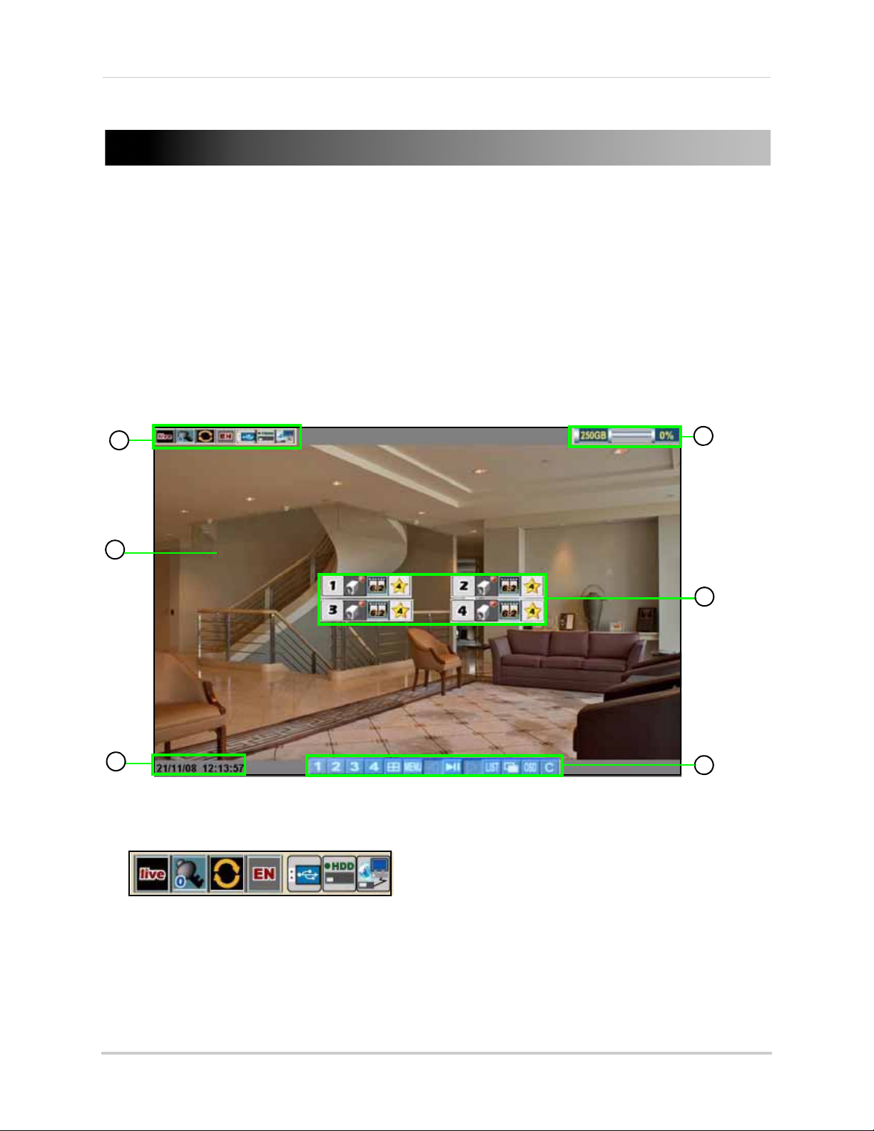
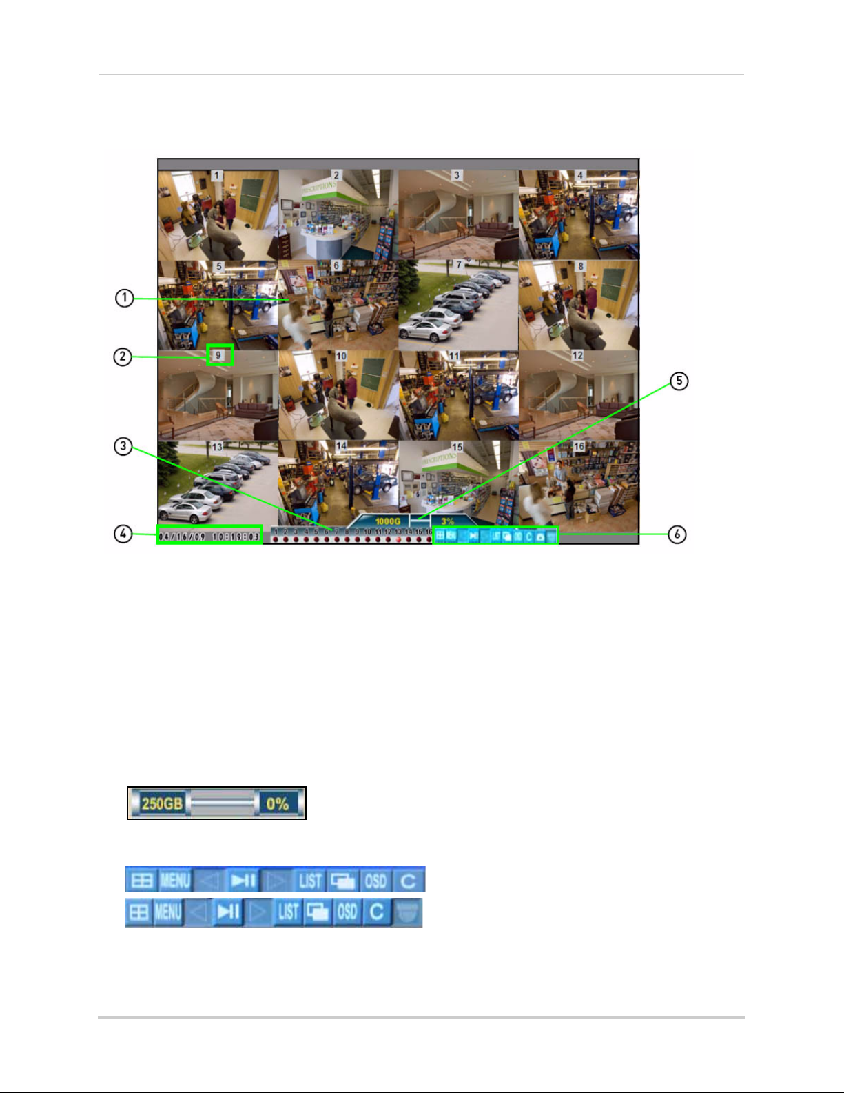
Figure 4.0 Live viewing with on-screen display (4-channel model)
2
6
1
5
4
3
STARTING THE SYSTEM
To power the system ON:
• Connect the power cable to the DC 12V port on the rear panel of the system
At startup, the system performs a basic system check and runs an initial loading sequence. After
a few moments, the system loads a live display view (
NOTE: Make sure all cameras and cables are properly connected prior to powering on the system.
Live Mode
Onscreen Display
4-channel
).
1. System Status Bar: Displays mode, password type, recording mode, language, and status of devices (HDD and USB).
2. Display: Full-screen single channel and Quad split-screen available in Live Viewing and Playback modes; if cameras are disconnected, channels display a blue screen with the text, "VLOSS."
11
Page 26
Starting the System
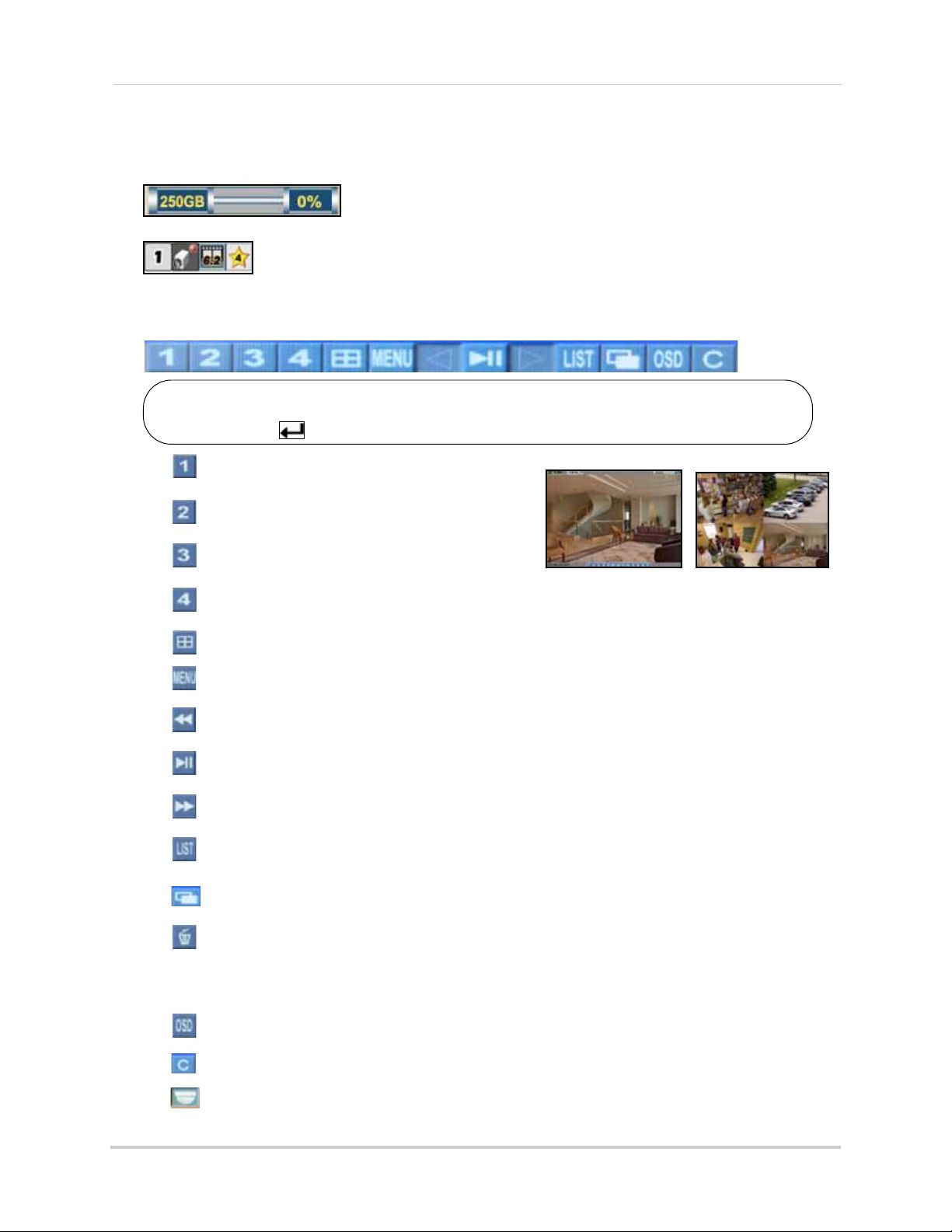
Toolbar icons are based on firmware version 7.28.08_1890C (4-channel) and
1.45.08_1890C (8 &16 channel) and above. To check your firmware version,
press the button twice on the remote.
Figure 4.1 Single channel and Quad (4-channel model)
3. HDD Status: Displays the recording space consumed on the hard disk (%) and the size of the
pre-installed hard drive. For example, 250 GB
.
4. Camera Status: Displays channel number, recording status, frame rate, and video quality.
5. Date/Time: Displays the date and time on the system.
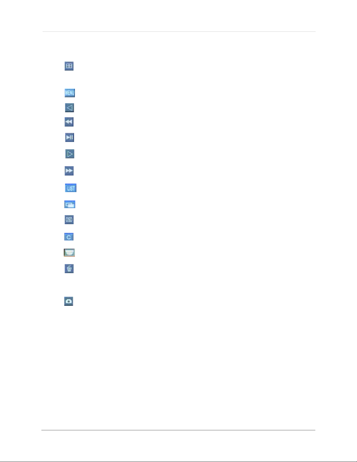
6. Toolbar: Primary control input for the user interface:
• : Click to view channel 1 in full-screen.
• : Click to view channel 2 in full screen.
• : Click to view channel 3 in full screen.
• : Click to view channel 4 in full screen.
• : Click to view Quad split-screen mode (Live View and Playback modes).
• : Click to open the system Main Menu. See “Using the Main Menu” on page 29.
• : While in Playback mode, click to increase reverse playback speed (5X, 15X, 60X).
• : From Live View, click to open Playback Mode; click to pause/play video.
• : While in Playback mode, click to increase forward playback speed (5X, 15X, 60X).
• : Click to open the Event List menu. See “Event List” on page 21.
• : Click to begin sequence view.
• : From the Event List menu, click to delete a selected video file.
NOTE: Be careful when clicking the Trash icon—there is no confirmation for deletion and you
undo the action.
cannot
• : Click to show/hide the on-screen display (OSD).
• : Click to return to the previous menu, and/or quit menus/modes
• : Opens the PTZ menu (PTZ camera required ,not included, EDGE+ LH320 Series only).
12
Page 27
8/16-channel
Figure 4.2 Live viewing with onscreen display (16-channel model shown)
EDGE (LH310 series) , Edge mini (LH304)
EDGE
+
(LH320 series)
Figure 4.3 Toolbar differences between the EDGE, EDGE+ and EDGE mini.
Starting the System
1. Display Screen: Shows live and recorded video—single, quad, and split-screen (16-split on
only
16-channel model
).
2. Camera Number/Title: You can set the display to show the Camera Number, Title, or show no title.
3. Channels: Displays channels on the system. Icons flash red to indicate recording is in progress.
4. Date/Time: Displays the date and time on the system.
5. HDD Status: Displays the recording space consumed on the hard disk (%) and the size of the
pre-installed hard drive. For example, 250 GB
. This reading is an approximation.
6. Toolbar: Primary control input for the user interface (certain buttons will not be available at all times):
13
Page 28
Starting the System
• : Click to open the Split-Screen Selector; from full-screen (Live Mode only), click once
to view quad, click again to open Split-Screen Selector. See “Using the Split-Screen
Selector” on page 15.
• : Click to open the system Main Menu. See “Using the Main Menu” on page 29.
• : Click to select a menu option (left).
• : Playback mode only—click to increase reverse playback speed (5X, 15X, 60X).
• : From Live View, click to open Playback Mode; click to pause/play video.
• : Click to select a menu option (right).
• : While in Playback mode, click to increase forward playback speed (5X, 15X, 60X).
• : Click to open the Event List menu. See “Event List” on page 21.
• : Click to begin sequence view.
• : Click to show/hide the on-screen display (OSD).
• : Click to return to the previous menu, and/or quit menus/modes
• : Opens the PTZ menu (PTZ camera required, not included, EDGE+ (LH320 series only).
• : From the Event List menu, click to delete a selected video file.
NOTE: Be careful when clicking the Trash icon—there is no confirmation for deletion and you
undo the action.
cannot
• : Click to take a snapshot of the active display (live viewing or playback) (8 or 16 channel
models only).
NOTE: USB flash drive must be connected. For more details, see “Troubleshooting” on page 111.
14
Page 29
Starting the System
ATTENTION: Split-Screen Selector is only available on
8/16-channel models only
.
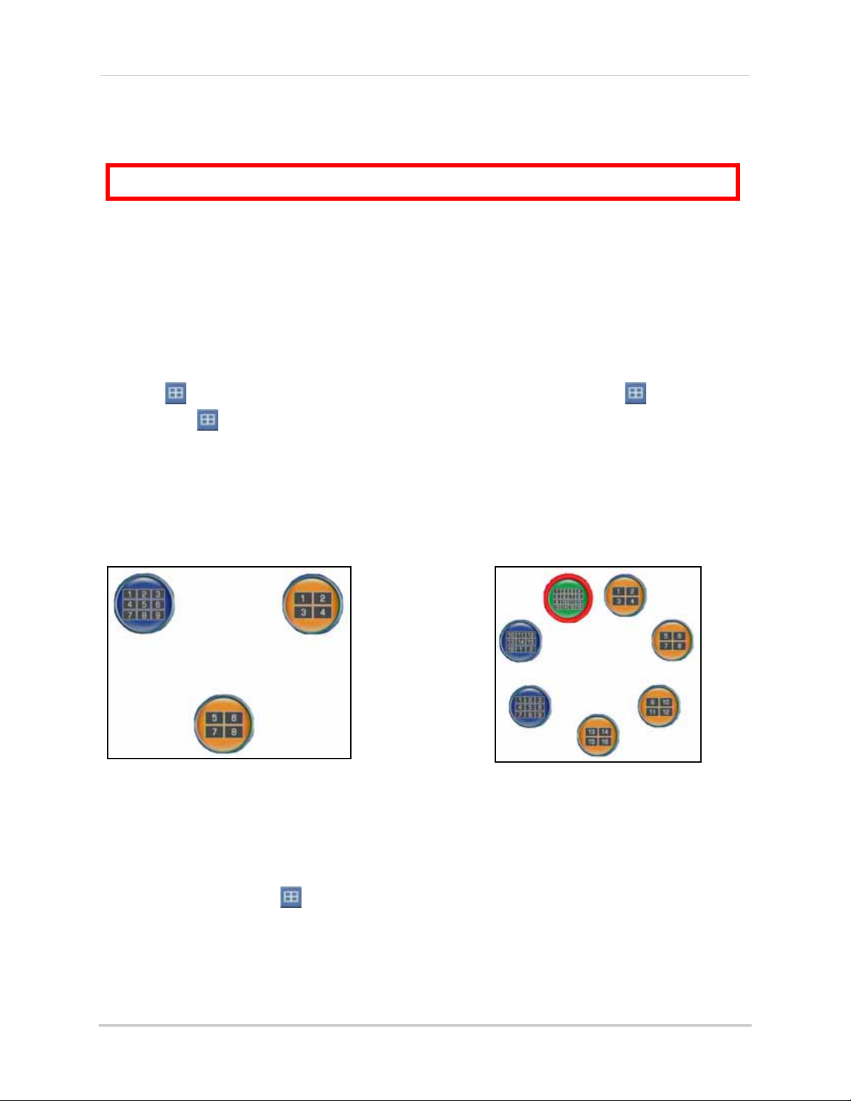
Figure 4.4 Split-Screen Selector (8-channel)
Figure 4.5 Split-Screen Selector (16-channel)
Using the Split-Screen Selector
If your system has 8/16-channels, you must choose a split-screen configuration using the
Split-Screen Selector built into the system’s interface. The Split-Screen Selector allows you to
choose the grid configuration for the main display during live viewing and playback: quad, 9-split,
or 16-split (16-channel
Live Viewing
To use the Split-Screen Selector:
1. Click to open the Split-Screen Selector. If you are in full-screen, click to view quad,
then click again to open the Split-Screen Selector. Grid configurations appear in circles
onscreen.
2. Click a grid configuration for live viewing:
only
).
•
8-channel
remain blacked out).
•
16-channel
or 16-split (CH1~16).
: Choose from quad (CH1~4, CH5~9) or 9-split (CH1~8; the bottom-right square will
: Choose from quad (CH1~4, CH5~9, CH9~12, CH13~16), 9-split (CH1~9, CH10~2),
Playback
To use the Split-Screen Selector:
1. During playback, click at anytime to open the Split-Screen Selector.
NOTE: The Split-Screen Selector will open even if you are viewing playback in full-screen.
2. Click a grid configuration for playback.
15
Page 30
Starting the System
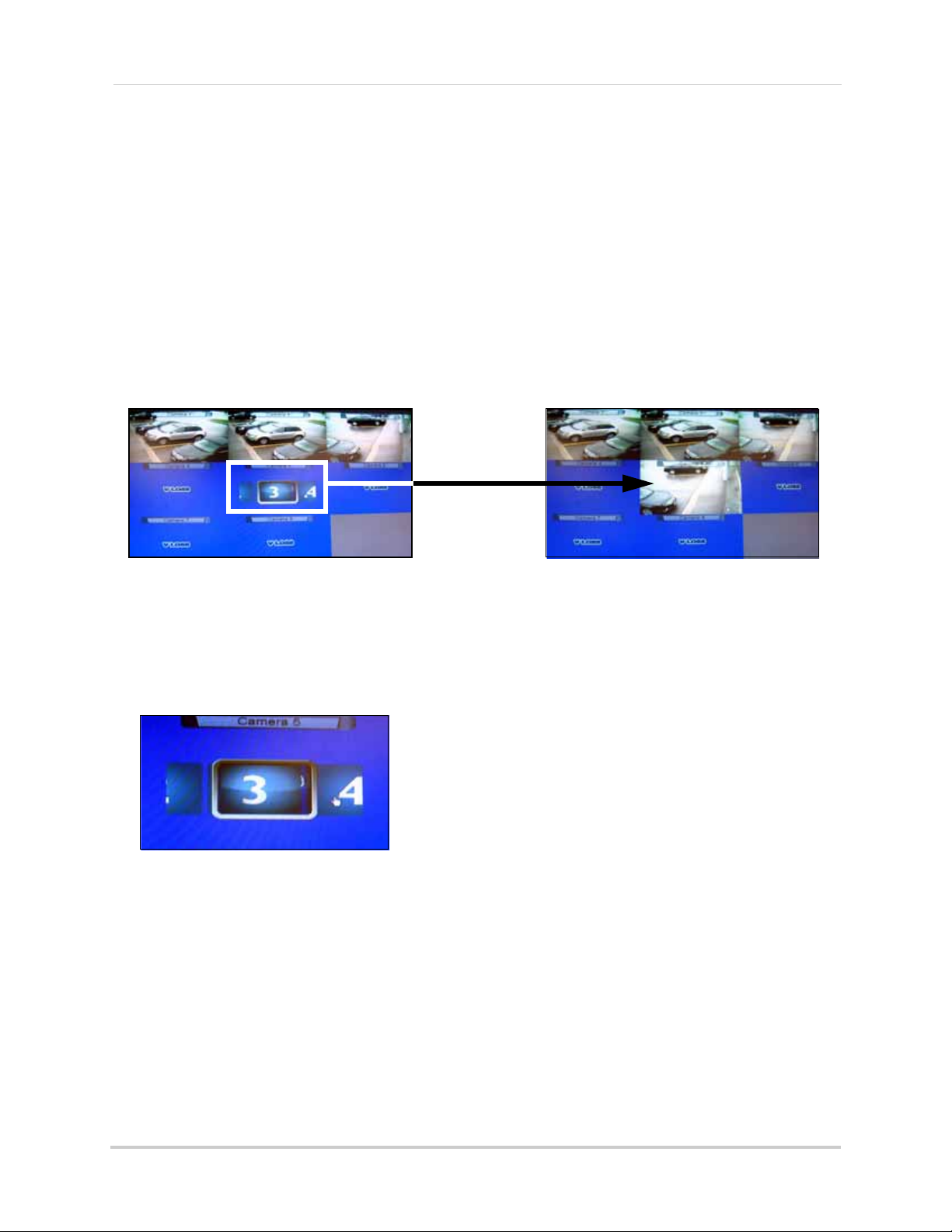
EXAMPLE
Channel 3 is re-assigned to channel 5.
Figure 4.6 Re-assigning camera positions.
Figure 4.7 The channel menu.
Flexible Camera Assignment
You can re-assign camera channels to different positions. For example, you can duplicate the
video feed from channel 1 onto channel 2.This is useful if you wish to re-arrange the position of
each channel.
NOTE: This feature is avaliable on 8/16 channel systems only.
NOTE: The system continues to record the designated channel even if you re-assign camera
positions.
To re-assign camera positions:
1. Select the channel you want to have re-assigned.
2. Click and hold the mouse.
• A channel menu appears.
3. While holding left-click, move the mouse to the left or right to change the channel number.
4. Release left-click on the mouse to assign the new channel.
16
Page 31

SETTING THE DATE AND TIME
Figure 5.0 Clock menu
It is highly recommended to immediately set the date and time when first setting up your system.
To set the date and time:
1. Click to open the Main Menu.
2. Click to open the Setup menu.
3. Click Date/Time Setup and configure the following options:
• Date Mode: Use the scroll wheel to select Y/M/D, D/M/Y, or M/Y/D.
• Date: Use the scroll wheel to manually enter the date.
• Time: Use the scroll wheel to manually enter the time.
4. Click Exit/Update. The new date and time are saved; the system returns to the Setup menu.
5. Right-click to exit until all menus are closed. The date and time will appear on the bottom-left corner of the screen.
17
Page 32

RECORDING
By default, the system is set to immediately record video from connected cameras in Continuous
Record Mode.
You can set the system to stop recording once the hard drive is full, or to continually record by
overwriting previously recorded data. For more details,
Event Recording
The system includes three modes of event recording:
• Motion: The system records when motion is detected by the affected camera.
• Alarm: The system records when an alarm or sensor is triggered.
• Video Loss: The system records when a camera is disconnected or suffers video
loss. The system employs a pre-record function to capture video seconds before
the video loss occurred.
Recording Audio
The system can record two audio channels (on channel 1 and 2 only). You must have audio enabled
cameras connected to the system in order to use this function.
see “Record” on page 31.
18
Page 33

PLAYBACK
Figure 6.0 Playback display view
The playback time appears in the bottom-right
corner of the screen.
View recorded video on the system through playback mode.
To begin playback:
1. From the main screen, click . Playback mode opens.
NOTE: If toolbar is not visible, first click .
2. Select and change the date, month, year, time, and/or frame for playback and click .
3. During playback, you have access to the following:
• : Click to pause playback; press again to resume playback.
• : Click to increase reverse playback speed (5X, 15X, 60X).
• : Click to increase forward playback speed (5X, 15X, 60X).
• : Click to open the Split-Screen Selector (8/16-channel
Quad mode (4-channel
•
: Click to open the Event List menu. See “Playback Mode” on page 24.
only
)
only
); Click to view playback in
4. Click any channel to view the selected channel in full-screen; or click , , , .
5. Click anywhere in the playback bar to set a playback marker. Playback Markers can be used
for faster searching in the Event List.
See “Playback Markers” on page 20.
6. Right-click anywhere on the screen to exit.
19
Page 34

Playback
Figure 6.1 Playback display view
Playback Markers
During playback, click anywhere in the playback bar to set a playback marker. Use this
orange-colored marker for reference in future searches.
Additional Search Markers
The Playback bar can also be populated with other multi-colored markers. These markers are
part of the
“Event List” on page 21.
Smart Search
functionality of the system. For more details on Smart Search, see
To use the search markers:
1. Using the mouse, scroll up/down to position one of the colored markers in the Playback Target.
2. Click .
20
Page 35

EVENT LIST
Figure 7.0 Event List
Edge+ & Edge mini tool bar uses the letter "C" for the escape function.
If you have not upgraded your DVR firmware to the latest, you may
see the old toolbar shown above.
16-channel models
4-channel models
The system features an Event List to organize and search for recorded video on the system. The
Event List, coupled with the Smart Search icons, allows you to search for recorded data on your
system quickly and easily.
NOTE: The system can save a maximum of 4096 events (4-channel) / 8192 events (8 & 16-channel).
1. Channel Filter: View data from all, or individual cameras.
2. Smart Search: Filter events through Smart Search icons.
3. Event Details: View details for the event, including date & time and event source.
4. Events: List of recorded events on the system.
5. Active Toolbar Buttons: While in Event List, use Play/Pause, Trash (delete), and C (Escape).
NOTE: The Escape button is only on Edge and Edge mini models. Screenshot button appears on 8/
16-channel models.
Channel Filter
Use the Channel Filter to sort the data from individual channels or all channels.
21
Page 36

Event List
Figure 7.1 Smart Search Icons
Event Number
Camera ON/OFF
Filter Type
Date & Time
Event Source
Figure 7.2 Event Details icons
Smart Search
Click the Smart Search icons to filter data according to events. These Smart Search icons are
mirrored as event markers in Playback and Backup modes.
Event Details
The event details (event number, camera on/off, filter type, date & time, and event source)
immediately match the list of events. When you use the Camera filter and Event filter, the Event
Details bar can help you view the pertinent information for the data.
22
Page 37

Event List
Searching for Recorded Data
You can use the Event List from Live Mode and Playback Mode to search for recorded data on your
system.
Live Mode
To search for data:
1. From the main screen, click . The Event List opens.
2. Under Channel Filter, click to view events for
view events from
3. Click the Smart Search icons to sort the data according to the following:
• ALL: View all events chronologically.
• Motion: Motion events from the connected cameras.
• Video Loss: Cameras are disconnected or suffer video loss. The system employs
• Alarm: Alarm or sensor events on the system.
• HDD ON/OFF: Disconnection, power loss, or disk failures on the hard drive.
• Power ON/OFF: System ON/OFF.
• Mark: A personal marker set by the user during Playback Mode.
individual
NOTE: USB backups appear at the top of the list if the USB flash drive with saved backup data is connected.
a pre-record function to capture video seconds before the loss of video occurred.
channels.
ALL
channels, or click the Channel icons to
• USB: USB backup performed by the user
4. Scroll up/down to view the events on the list.
5. Click an event and then click . System switches to Playback Mode.
NOTE: You cannot begin playback after clicking or
6. To exit, right-click until you return to the main screen.
23
Page 38

Event List
Playback Mode
To search for data:
1. From the main screen, click . Playback mode opens.
NOTE: If toolbar is not visible, first click .
2. Click . The Event List opens.
NOTE: Click for Edge 8/16-channel models.
3. Under Channel Filter, click to view events for
to view events from
4. Click any of the Smart Search icons to filter your search.
5. Scroll up/down to view the events on the list.
6. Click an event from the Event List and then click . Playback begins for the selected file.
NOTE: You cannot begin playback after clicking or .
You can click while a file is playing. Playback will pause. Select a new file from the Event List
and then click to play the file.
individual
channels.
ALL
channels, or click the Channel icons
24
Page 39

TAKING SCREENSHOTS
ATTENTION:
8/16-channel models only
.
Figure 7.3 Screenshot being taken on the system
If your system has 8 or 16 channels, you can take screenshots (screen captures) of the main
display of your system. You can take a screenshot at any time: during live viewing, search, and
playback, or in any system menu. Screenshots are useful if you need to provide a still image of
your security footage to the authorities.
NOTE: A USB flash drive must be connected and formatted to the system in order to take
screenshots.
To take a screenshot:
1. Connect a USB flash drive (not included) to the USB port on the front panel of the system.
Format the USB flash drive if you have not already done so. For more details,
the USB Drive” on page 38.
2. If you want to capture a point in live viewing or playback, select the display view for the screenshot: single, quad, or split-screen.
3. Click . The screenshot will appear in the centre of the main display, followed by the file
name. Screenshots are saved to the
Picture folder
on the USB flash drive.
see “Formatting
NOTE: Screenshots are saved as JPEG files with the following naming convention: KMMDD00x.jpg
Filename Definition
K System file marker (all screen caps begin with K)
MM Month
DD Day
x Numeral (i.e. 001, 002, 003, etc.)
25
Page 40

Taking Screenshots
Figure 7.4 AutoPlay screen
Using Screenshots
Once you have taken screenshots, you need to connect the USB flash drive to a PC to view, print,
or archive the images.
To use screenshots:
1. Connect the USB flash drive to a USB port on your PC. In the AutoPlay window, select Open
folder to view files.
NOTE: If AutoPlay does not start, search your computer for a
Removable Disk
.
2. Double-click the Picture folder.
3. Perform one of the following:
•
View
: Double-click the screenshot to view it in an imaging program, such as Windows Picture
Viewer or Adobe
•
Archive
•
Print
: Copy the images to a folder on your computer
: Select the image and print it directly from Windows Explorer, or print the screenshot
®
Photoshop
from an imaging program
™
26
Page 41

MANAGING PASSWORDS
LEVEL ID PASSWORD
USER 1 1111
ADMIN 2 2222
LEVEL ID PASSW ORD
USER 2 2222
ADMIN 3 3333
LEVEL ID PASSWORD
GUEST 7 1111
USER 8 2222
ADMIN 9 3333
8 & 16 Channel
4/ 8/ 16 Channel
4 Channel
Local DVR Access
Remote/LAN Viewing
Figure 8.0 Login with your user ID and password using the Password Wheel
Refer to the tables below for the user name (ID) and password required to log in to your system:
Using the Password Wheel
The system uses a graphical Password Wheel for inputting and changing user IDs and 4-digit,
numeric passwords.
To use the Password Wheel:
• Using the mouse, move the cursor and click from 0~9.
You cannot select the options to the left of the Password Wheel (user ID, password)—you can
select the digits. If you make a mistake, simply right-click to exit and re-select the option to try
again.
Enabling and Disabling Passwords
By default, passwords are disabled when you first startup the system. With passwords enabled,
you need to enter your user ID and password whenever you access the system Main Menu, Event
List, or Playback mode.
To enable/disable passwords:
1. Click to open the Main Menu. If necessary, login to the system.
2. Click . The Setup menu opens.
3. Click Password Enable and scroll up/down to select O to enable passwords, or X to disable.
4. To exit, right-click until you return to the main screen.
only
27
Page 42

Managing Passwords
Figure 8.1 Password change
Figure 8.2 Password confirmation
Changing Passwords
You need to be logged in as the administrator in order to change passwords on the system.
To change passwords:
1. Click to open the Main Menu.
NOTE: In older firmware models, click .
2. Click . The Setup menu opens.
3. Click DVR Password. The Password Wheel opens.
4. Log in as the administrator.
5. Click either User Password or Admin Password.
6. Use the Password Wheel to input a 4-digit password. Input it again to confirm.
7. To exit, right-click until you return to the main screen.
28
Page 43

USING THE MAIN MENU
1
2
4
3
5 6
Figure 9.0 System Main Menu
When navigating
menus
:
Left mouse button:
Click to select menu options
Scroll-Wheel: Scroll up/
down to change values for
selected options
TIP!
Depending on your DVR model:
• Click to open the Main Menu OR
Using the Main Menu
• Click
to open the Main Menu
NOTE: If passwords are enabled on the system, you need to select your user ID and enter the four-digit
numerical password to open the Main Menu.
See “Managing Passwords” on page 27.
1. Camera: Adjust Brightness, Contrast, Hue, and Saturation for each camera.
2. Setup: Configure Date/Time, Language, video system, passwords, and view system information.
3. Record: Configure recording parameters for Alarm/Motion recording, and working/non-recording; adjust video quality, resolution, set record mode, schedule, and format the hard drive
4. Alarm: Configure alarm, motion, and video loss settings.
5. Backup: Set backup parameters; format connected USB flash drive.
6. LAN: View/configure networking settings.
29
Page 44

Using the Main Menu
Figure 10.0 Camera menu
Figure 11.0 System Setup
Figure 11.1 System Languages
Camera
Configure display settings for each camera.
To configure camera color settings:
1. From the Main Menu, click . The Camera menu opens.
2. Select Color Adjust.
3. Click camera 1, 2, 3, or 4. The video settings menu opens.
4. Configure the following:
• Brightness
• Contrast
• Hue
• Saturation
5. Scroll up/down to increase/decrease the value for the selected option.
6. To save your settings, right-click until you return to the main screen.
To configure camera sequence dwell settings
+
(Edge
, Edge Mini only):
Setup
Set date/time, system language, passwords,
and view system information.
To configure Setup settings:
1. From the Main Menu, click . The Setup menu opens.
2. Configure the following:
• Load Default: Click to load default factory
settings.
• Language: Select English, Traditional
Chinese, Spanish, Russian, Italian,
Simplified Chinese, Japanese, German,
French, Dutch, Czech, Polish, Hebrew,
Thai, Danish, Finnish, Swedish,
Vietnamese, Turkish and Korean.
NOTE: The new language is reflected in
the status bar in the top-left corner
only
(4-channel
).
1. From the Main Menu, click . The Camera menu opens.
2. Click on Sequence Time.
3. Scroll the mouse wheel to adjust the sequence duration.
• To begin a sequence, click in the
menu bar.
NOTE: Sequence Time refers to the time the camera channel changes to the next camera channel (in single channel view).
30
• NTSC/PAL Select: Scroll up/down to select
NTSC (I.e. North America), PAL (i.e. Europe),
or AUTO. If AUTO, the system will
automatically detect the format of the
connected cameras.
Page 45

Using the Main Menu
Figure 11.2 System information
Figure 12.0 Record menu
Figure 12.1 Frame rates for NTSC and PAL
Figure 12.2 Set image quality: 1 basic ~ 5 excellent
To enable motion recording
only, set the Working and Non
Working hour frame rates to 0.
Motion recording in the Alarm
menu must also be enabled.
TIP!
• Fan Speed: Click to set the fan speed to
Low, Middle, or High. The higher the fan
speed the cooler the HDD temperature (8/
16-channel
only
).
• Date/Time Setup: Click to open Date/Time
Setup. See “Setting the Date and Time” on
page 17.
• DVR Password: Click to open the
password menu. See “Managing
Passwords” on page 27.
• Information: Click to view system
information: software, hardware, disk,
and LAN.
3. To save your settings, right-click until you return to the main screen.
To configure record settings:
1. From the Main Menu, click . The Record menu opens.
2. Configure the following:
• Alarm/Motion Rate: Click under each
camera and select X, 2, 3, 5, 7.5, 10, or
15 (fps).
• Working Hour Rate: Click under each
camera and select 0, 2, 3, 5, 7.5, 10, or
15 (fps).
• Non-working Hour Rate: Click under
each camera and select 0, 2, 3, 5, 7.5,
10, or 15 (fps).
Record
Set recording parameters, image quality,
resolution, set the recording schedule, and
format the hard drive.
4-channel
• Quality: Click under each camera and
select 1, 2, 3, 4, or 5.
• Audio: Click under each camera and
select either O to enable audio or X to
disable audio.
NOTE: Audio is only available on
channels 1 and 2.
• Resolution: Click to set the resolution
for all cameras—640x240 or 640x480.
NOTE: As you make changes to the recording
parameters, the storage calculator at the
bottom of the menu displays the time remaining
on the hard drive.
31
Page 46

Using the Main Menu
Figure 12.3 Record menu (8/16-channel)
Figure 12.4 Frame Rate menu (8/16-channel only)
Figure 12.5 Frame rates for NTSC and PAL
• Record Mode: Select one of the following:
z Single-Way: The system
stops recording when the internal
hard drive is full.
z Overwrite: The system
continues recording when the
internal hard drive is full by
overwriting the oldest recorded
data.
z No Record: The system
not
record.
does
3. To exit, right-click until you return to the main screen.
8/16-channel
z Overwrite: The system
continues recording when the
internal hard drive is full by
overwriting the oldest recorded
data.
z No Record: The system
not
record.
does
• Video Frame Rate: Set the frame rates for
alarm/motion, working hour, and
non-working hour:
NOTE: As you make changes to the recording
parameters, the storage calculator at the
bottom of the menu displays the time remaining
on the hard drive.
To configure record settings:
1. From the Main Menu, click . The Record menu opens.
2. Configure the following:
• Video Information: View video quality
statistics
• Record Mode: Click to select one of the
following:
z Single-Way: The system
stops recording when the internal
hard drive is full.
z Alarm/Motion Rate: Click under
each camera and select X, 2, 3, 5,
7.5, 10, or 15 (fps).
z Working Hour Rate: Click under
each camera and select 0, 2, 3, 5,
7.5, 10, or 15 (fps).
z Non-working Hour Rate: Click
under each camera and select 0, 2,
3, 5, 7.5, 10, or 15 (fps).
z Real Rate: The system will
automatically calculate and
allocate a
Real Rate
when you
change the Working Rate.
32
Page 47

Using the Main Menu
Figure 12.6 Set image quality: 1 basic ~ 5 excellent
Figure 12.7 Recording Schedule
• Working Hour
• Non-working Hour
z Quality: Click under each camera
and select 1, 2, 3, 4, or 5.
z Audio: Click under each camera
and select either O to enable audio
or X to disable audio.
NOTE: Audio is only available on channels
1 and 2.
z Resolution: Click to set the
resolution for all cameras—
640x240 or 640x480.
To exit, right-click until you return to the main
screen.
Schedule
4/8/16-channel
Set an hourly, daily, and/or weekly recording
schedule.
The Recording Schedule is a grid featuring the
days of the week and hours 0~23.
Active recording is known as
(yellow)
and non-recording is known as
Non-working Hour (green)
Working Hour
.
NOTE: As you make changes to the recording
parameters, the storage calculator at the
bottom of the menu displays the time remaining
on the hard drive.
To set a recording schedule:
1. From the Record menu, click Schedule. The Recording Schedule grid opens.
2. Click an hour square (0~23) in each weekly row (Sun~Sat): active squares turn yellow, inactive turn green.
3. To save your settings, right-click or until you return to the main screen.
NOTE: Alarm or Motion Recording recording
will not be affected by the recording schedule.
33
Page 48

Using the Main Menu
ATTENTION: Formatting the HDD erases
all data
on the hard disk.
This step cannot
be undone
.
Figure 12.8 Storage calculator
Figure 12.9 Storage calculator
Figure 13.0 Alarm menu (4-channel)
Format HDD
If you replace the pre-installed hard drive, the
must
new drive
function properly with the system.
To format the hard disk:
1. From the Main Menu, click . The Record menu opens.
2. Click Format HDD.
3. Click Yes to format the hard disk or click No to cancel.
Please allow a few moments for formatting to
take place and the system to reset.
Storage Calculator
A storage calculator shows the approximate
maximum continuous recording time available
on the hard drive based on your settings. Use
the storage calculator to help maximize your
hard drive space.
be formatted in order to
Alarm
4-channel
Configure alarm and motion detection
settings.
To configure the alarm settings:
1. From the Main Menu, click . The Alarm menu opens.
2. Click and edit the following:
• Video Loss Alarm: Click under each
camera and select either O to enable
the VLoss alarm, or X to disable it. If
enabled, the system will sound an
alarm whenever one of the connected
channels incurs a loss of video.
• Motion Enable: Click under each
camera and select O to enable motion
detection or select X to disable it. If
enabled, the camera can record in
specific recording parameters when it
detects motion.
NOTE: With Motion Detection enabled, the
text, "Motion" appears on-screen
(full-screen and quad split-screen)
whenever a motion event is triggered.
NOTE: The estimation from the Storage
Calculator is based
Recording, not motion or alarm recording.
34
only
on Continuous
• Buzzer: Select O to enable the system
to beep when an alarm is triggered or
motion is detected; select X to disable
it.
• Key Buzzer: Select O to enable the
system beep when you click the mouse,
press the buttons on the remote/front
panel. Select X to disable the beep.
Page 49

Using the Main Menu
Figure 13.0b Alarm Input & Output menu
Figure 13.0c Alarm-In Setup menu
Figure 13.0d Alarm-Out Setup menu
Alarm Input & Output Menu
• Alarm-In Type: Select NO (normally open)
or NC (normally closed) for the alarm in
device.
• VLoss Response Time: Select the time (in
seconds) for the system to record prior to
a triggered event: 0, 3, 5, 10, 30, 60, 120,
180, or Infinite.
• Response Duration: Select the time (in
seconds) for the system to record after a
triggered alarm or motion event: 1~255.
NOTE: The Response Duration also applies to the
accompanying message and/or buzzer.
Alarm-In Setup Menu
2. Click to assign an Event notification (Motion, VLoss, Alarm, HDD ON/OFF) to an Alarm-Out notification (Buzzer, Alarm Full-Screen, Label, Alarm Out 1).
• Buzzer: Select O to enable the system
to beep when an alarm is triggered or
motion is detected; select X to disable
it.
• Alarm Full Screen: Select O to enable
a full-screen display of the active
alarm/motion channel; select X to
disable it.
• Label: Select O to enable the system to
display camera OSD when an alarm
triggers.
• Alarm Out 1: Alarm 1 output.
3. To save your settings, right-click until you return to the main screen.
To configure the Alarm-In Setup:
1. Click Alarm-In Setup.
2. Click on the desired alarm number (alarm 1~4) and assign it to the desired camera number.
Alarm-Out Setup Menu
To configure the Alarm-Out Setup menu:
1. Click Alarm-Out Setup.
35
Page 50

Using the Main Menu
Figure 13.1 Alarm menu (8/16-channel)
Figure 13.2 Alarm Input & Output menu
Figure 13.3 Alarm-In Setup menu (8/16-channel
only
)
Figure 13.4 Alarm-Out Setup menu
8/16-channel
To configure the alarm settings:
1. From the Main Menu, click . The Alarm menu opens.
2. Click and edit the following:
• Video Loss Alarm: Click under each
camera and select either O to enable
the VLoss alarm, or X to disable it. If
enabled, the system will sound an
alarm whenever one of the connected
channels incurs a loss of video.
press the buttons on the remote/front
panel. Select X to disable the beep.
• Alarm Input & Output: Click to open the
Alarm Input & Output menu.
• Alarm-In Type: Select OFF/ NO
(normally open) / NC (normally closed)
to select alarm type.
• Alarm-In Setup: Click to open the
Alarm-In Setup menu. Click to assign
channels to up to four alarms.
• Motion Enable: Click under each
camera and select O to enable motion
detection or select X to disable it. If
enabled, the camera can record in
specific recording parameters when it
detects motion.
NOTE: With Motion Detection enabled,
the text, "Motion" appears on-screen
(full-screen and quad split-screen)
whenever a motion event is triggered.
• Buzzer: Select O to enable the system
to beep when an alarm is triggered or
motion is detected; select X to disable
it.
• Key Buzzer: Select O to enable the
system beep when you click the mouse,
• Alarm-Out Setup: Click to open the
Alarm-Out Setup menu. Click to assign
an Event notification (Motion, VLoss,
Alarm) to an Alarm-Out notification
(Buzzer, Full-Screen, Label, Alarm Out
1).
• VLoss Response Time: Select the time
(in seconds) for the system to record
prior to a triggered event: 0, 3, 5, 10, 30,
60, 120, 180, or Infinite
36
Page 51

Using the Main Menu
• Enabled (yellow)
•
Disabled (green)
Figure 13.5 Alarm/Motion Schedule (8/16-channel
only
)
Figure 13.6 Select the camera for motion detection (4-channel)
• Motion Detection
Disabled
Figure 13.7 Select cells and adjust sensitivity
• Motion Detection
Enabled
• Response Duration: Select the time (in
seconds) for the system to record after
a triggered alarm or motion event:
1~255.
NOTE: The Response Duration also
applies to the accompanying message
and/or buzzer.
• Alarm/Motion Schedule: Click to
enable/disable the Alarm/Motion
Schedule for each day of the week/
hours 0-23.
3. Click Motion. Select the camera you want to configure motion detection. The motion grid appears for the selected camera.
4. Click within the grid to enable/disable individual motion cells. Enabled cells are light green; disabled cells are clear.
• Select the size of the selection cursor by
clicking: 1x1 , 1x13, 3x5, 3x13, 5x9, 7x13
• To save your settings, right-click until you
return to the main screen.
Motion
4/8/16-channel
Set the motion detection cells and sensitivity
for each camera.
To configure motion detection:
1. From the Alarm menu, click Motion Enable. The text, "Motion" will appear on-screen when motion is detected on the respective camera.
2. Choose a camera for motion detection and select O.
5. Click the Sensitivity bar at the bottom of the screen. Scroll up/down to increase/ decrease the sensitivity for the motion cells from 0~100. The higher the number, the greater the sensitivity.
NOTE: Sensitivity applies to all cells. If the
Sensitivity bar is not visible, click
.
6. Click to enable/disable the entire grid.
7. To save your settings, right-click until you return to the main screen.
37
Page 52

Backup
Figure 14.0 Backup menu
ATTENTION: Formatting erases
all data
on the USB flash drive. This step
cannot
be undone.
Figure 14.1 Confirm formatting
Set start and stop times for recorded video
data you wish to copy to a connected USB flash
drive (not included).
NOTE: The system supports most brands of
USB flash drives from 128 MB ~ 8 GB.
Formatting the USB Drive
Prior to backing up data, you must first format
the USB flash drive so it will function properly
with the system.
4. Click Yes to format the hard disk or click No to cancel.
Please allow a few moments for formatting to
take place and the system to reset.
To backup data:
1. Connect a formatted USB flash drive to the USB port on the front panel.
NOTE: Do not connect a USB flash drive to the
USB port on the rear panel. Only the port on the
front panel has been designed for backup data
transfer.
2. From the Main Menu, click . The Backup menu opens.
3. Click Start Time, and select the date, month, year, and time to begin the backup. Event Markers will appear in the Time Bar as you scroll through the date and time.
4. Click Stop Time, and select the date, month, year, and time to begin the backup.
To format the USB drive:
1. Connect a USB flash drive to the USB port on the front panel on the system.
NOTE: Do not connect a USB flash drive to the
USB port on the rear panel. Only the port on the
front panel has been designed for backup data
transfer.
2. From the Main Menu, click . The Backup menu opens.
3. Click Format.
NOTE: Event Markers will appear in the Time Bar as you set through the Start and Stop times.
5. Click Select Channel, and select a channel for backup.
6. Click Save. Backup begins—the on-screen
counter displays the progress of the
transfer based on the selected start and
stop times.
7. To cancel Backup, right-click until you return to the main screen. Please allow a few moments for the system to exit.
NOTE: Backup may take several moments
depending on the size of data being transferred.
38
Page 53

Confirming Backup
Setting Quicktime as a default media
To verify that the file has been properly backed
up:
1. Click to open Event List.
2. Click from the Smart Search event filter.
3. Select the file and click . The backup file should begin playing.
4. To exit, right-click until you return to the main screen.
Backup File Information
Backup files are saved as MOV files. These
files can be played on the system using Event
List or on your PC using QuickTime Player.
“Event List” on page 21.
Backup files are labeled according to the
following naming convention:
ch_##YYYYMMDDhhmmss.mov:
See
player
It is recommended to set Quicktime as your
default media player. This allows you to
double-click on a backed up video file, and
have the file play automatically.
To set Quicktime as your default player:
1. Right-click on the backed up video file you wish to view.
2. Move the cursor to Open With.
3. Click on Choose Default Program.
4. Under Recommended Programs, select QuickTime Player and then click OK.
NOTE: For the latest version of QuickTime,
go to
www.apple.com/quicktime/download/
You can back up video with audio in channels 1 and 2 only. Be sure to enable audio in the Recording menu.
Filename Definition
ch_## Channel number (1~16)
YYYY Ye ar
MM Month
DD Day
hh Hour
mm Minute
ss Second
Playing Saved Video
View your saved backup video files using
QuickTime Player.
To playback MOV files:
1. On your PC, open the folder where you
saved the MOV
default, converted files use the following
naming convention:
2. Double-click the file to open it in QuickTime Player.
file (by default, C:\). By
bv3.mov
39
Page 54

Using the Main Menu
Figure 15.0 LAN menu
Figure 15.1 : Easy Connect menu.
Figure 15.2 : Log File window.
LAN
Configure network settings.
From the Main Menu, click . The LAN
menu opens.
NOTE: Some networking knowledge is required
when adjusting options in the LAN menu.
To configure network settings:
1. Select the following, and use the scroll-wheel to change values:
• IP
• Mask
• Gateway
• DNS Server
• DHCP Enable
• HTTP Port
• Easy Connect
2. To save your settings, right-click until you return to the main screen.
NOTE: DCHP allows you to quickly connect to
your network by obtaining an IP address from
the router. After the initial setup, we recommend
that you disable DHCP and change the last set
of numbers in the IP address between 2~99. For
example, if your IP address is 192.168.0.107,
change the last digits to 90 (i.e. 192.168.0.90).
This ensures that port forwarding will not
change in the event of power failure or resetting
of your network.
NOTE: For added security, we strongly
recommend changing HTTP port 80 on the
system to
Internet service provider (ISP). For details on
changing ports on your system,
Ports On Your System” on page 42.
any desired port
not blocked by your
see “Changing
Easy Connect
Use the Easy Connect menu to enable Easy
Connect, and view the Easy Connect log.
For details on connecting to your system
remotely using Yoics,
Using Easy Connect” on page 61.
To enable Easy Connect:
• Select Yoics Enable, and use the scroll
wheel to select O to enable Easy Connect;
X to disable Easy Connect.
To reset Yoics:
• Click Reset Yoics.
NOTE: It may take several minutes for the changes to take effect. Restarting Yoics is used for troubleshooting only.
To view the Yoics Log:
• Click Log File.
see “Remote Viewing
40
Page 55

Using the Main Menu
Figure 15.3 LAN Passwords
ATTENTION: Formatting erases
all data
on the USB flash drive. This step
cannot
be undone.
LAN Password
Use the LAN Password to control Remote
Viewing access for Guest, User, and
Administrator profiles. The LAN password is
required if using the built-in browser-based
remote client software.
To change LAN passwords:
1. Select LAN Password and use the Password Wheel to login as the administrator (by default - 4 channel: ID: 2; password: 2222/ 8/16 channel: ID: 3; password 3333).
2. Only the administrator can edit and manage LAN passwords.
3. Select the following, and use the Password Wheel to change the LAN user ID and password:
• Guest Password: Lowest level network
user, with access to remote live viewing
only. By default, ID 7; pass: 1111.
• User Password: Normal level network
user, with access to remote live viewing
and playback only. By default, ID 8;
pass: 2222.
• Administrator Password: Highest level
user, with access to remote live
viewing, playback, and permissions to
change network configurations. By
default, ID 9; pass: 3333
Upgrading Firmware
Firmware upgrades can provide improved
functionality to your system. You can download
these free upgrades from
www.lorextechnology.com.
Prior to upgrading your system’s firmware,
you must first format the USB flash drive so it
will function properly with the system.
To upgrade firmware:
1. Connect a USB flash drive to the USB port
on the front panel of the DVR and format
(
see “Formatting the USB Drive” on
page 38.) Once formatting is complete,
remove the USB flash drive and connect it
to a USB port on your computer.
NOTE: The system creates two folders on your
USB drive:
2. In your web browser, visit your DVR manufacturer’s website and download the free firmware upgrade.
3. Copy the firmware file to the connected
USB flash drive—
either the Picture or Movie folder. Once the
file transfer is complete, remove the USB
flash drive from your computer.
4. Disconnect the power cable to power off your DVR and connect the USB flash drive. Reconnect the power cable.
5. The system will detect the USB drive and new firmware and begin the upgrade process. The system will prompt you when the upgrade is complete.
6. Remove the USB flash drive from your DVR and power off your system.
7. Power on the system. The system is now upgraded with the new firmware.
Picture
and
do not
Movie
.
place the file in
4. To save your settings, right-click until you return to the main screen.
41
Page 56

Changing Ports On Your System
If you change the default port on the system from 80 to a different value, you MUST enter http:// and the port number after the IP address.
For example, if you change your port number from 80 to 85, you MUST enter port 85 after the IP address, i.e. http://192.168.5.120:85.
There is a semi-colon after the IP address, followed by the port number.
Figure 15.4 Change the HTTP port
Figure 15.5 Confirm the new HTTP port
CHANGING PORTS ON YOUR SYSTEM
For added security, we strongly recommend
changing HTTP port 80 on the system to
port
—the port must not blocked by your Internet
service provider (ISP).
NOTE: Please contact your ISP for complete
information on available ports in your area.
Prior to changing ports on your system, you must
connect your system to your network using the
included Ethernet cable.
Example
Let’s say you want to change the HTTP port on your system from 80 to 85.
To change the port number:
any desired
1. Click to open the Main Menu and then click . The LAN menu opens.
2. From the LAN menu, select HTTP Port.
3. Use the scroll-wheel (or press on the remote control) to change the port number to 85.
4. Right-click to exit and save your settings (or press the ESC button on the remote control.
5. Disconnect the power cable from the rear panel of the system. Let the system power-down for 15~20 seconds and then reconnect the power cable.
6. To confirm that the new port number is saved on your system, the button twice on the remote control to view the System Information.
42
Page 57

Changing Ports On Your System
Figure 15.4 Enter :85 at the end of the IP address
Figure 15.6 Login with your LAN ID and password
You must now include the new HTTP port number in the URL when logging in to your system with
Internet Explorer.
NOTE: Requires Internet Explorer 6 or later.
Local Viewing:
To log in using the new port number:
1. Open Internet Explorer.
2. In the address bar, enter http://, then the IP address of your system immediately followed by :85 (no spaces). For example, http://192.168.1.89:85
3. Enter your
LAN ID
and
password
to log in to your system using DVR Netviewer.
43
Page 58

Changing Ports On Your System
ATTENTION: For remote viewing, the HTTP port of your system
MUST be port forwarded on
your router
—in this example, port 85. Each router is different, so port forwarding settings
vary by model. Please refer to the Lorex Port Forwarding Guide (www.lorexcctv.com/
support and then click Consumer Guides) for help on port forwarding your router. If your
router is not listed, please refer to your router's manual or contact your router's
manufacturer for assistance.
Figure 15.7 Your DDNS sub-domain should appear in System Information
NOTE: The system has a
4-character
display limit
for th e
DDNS subdomain. Please note
however, that
the complete
subdomain
(i.e. tomsmith)
is
saved by the system.
Remote Viewing:
You should now be able to access your system from your local network. Prior to using remote
viewing, you must log in to your system and enter the DDNS information from your Lorex DDNS
confirmation email.
NOTE: We strongly recommend registering for Lorex’s free DDNS service prior to using remote viewing.
For details,
To edit DDNS settings:
1. From a PC on your local network, open Internet Explorer.
2. In the address bar, enter http://, then the IP address of your system, followed by a semi-colon, then the port number (i.e. :85) . For example, http://192.168.1.89:85
3. Enter your LAN ID and password to log in to your system.
4. Click the Setup button and then click Network.
5. Click DDNS. Enter your DDNS information from the confirmation email and click Submit. For
complete details on entering your DDNS information,
on page 77.
6. Reset your system by disconnecting the power cable from the rear panel of the system. Let the system power down for 15~20 seconds and then reconnect the power cable.
see “Setting Up DDNS” on page 76.
see “Enabling DDNS on your system”
7. To confirm that the DDNS information is saved on your system, press the button twice on the remote control to view the System Information.
8. If you have not already done so, use the Auto Port Forwarding Software (included on CD) to port forward port 85 on your router or;
• Manually port forward your router. Each router is different, so port forwarding settings vary
by model. Please refer to the Lorex Port Forwarding Guide (www.lorexcctv.com/support and
then click Consumer Guides) for help on port forwarding your router. If your router is not
44
Page 59

Changing Ports On Your System
Figure 15.7 Enter :85 at the end of the DDNS URL
Figure 15.8 Login with your LAN ID and password
listed, please refer to your router's manual or contact your router's manufacturer for
assistance.
Now that you have configured your DDNS settings, you should be able to log in to your system from
a remote PC (i.e. a PC not on your local network).
NOTE:
4/8/16-channel
: The PC used for remote viewing requires Internet Explorer 6 or later.
To log in using DDNS:
1. Using a remote PC, open Internet Explorer.
2. In the address bar, enter your DDNS address immediately followed by :85 (no spaces).
NOTE: Obtain your DDNS address from your confirmation email.
3. Enter your LAN ID and password to log in to your system.
If you are having problems connecting using DDNS, check that you have port forwarded port 80 on
your router.
45
Page 60

REMOTE ACCESS: DVR Netviewer
Figure 16.0 DVR Netviewer Main Screen (8/16-channel)
Figure 16.1 Main screen (4-channel)
REMOTE ACCESS: DVR NETVIEWER
DVR Netviewer is the built-in browser-based remote surveillance software that allows you to
access your system from any PC with an Internet connection.
System Requirements
Prior to using DVR Netviewer, make sure your PC meets or exceeds the following system
requirements:
Description Requirement
CPU Intel Pentium® 4 3.0ghz or above (PC) / Intel Pentium Core Duo, 1.66 Ghz or above (Mac)
Operating
System
Memory 128 MB RAM
Video 16 MB of video memory
Network (LAN) 10/100 BaseT Network
Network
(WAN)
Browser Internet Explorer® 6 (or later); Mozilla Firefox is also supported but you need to install the IE
Media Player QuickTime Player 7 or later—visit www.apple.com to download the latest version
Windows XP®/Vista ®/ 7®
Apple OSX 10.5 or above
384 Kbps upstream*
*High-speed Internet service is recommended when using DVR Netviewer.
Tab plug-in (http://addons.mozilla.org) / Safari 4.0 and above
46
Page 61

Netviewer: Basic Layout
Figure 17.0: Four channel Netviewer.
Figure 17.1: Sixteen channel Netviewer.
LEVEL ID PASSWORD
GUEST 7 1111
USER 8 2222
ADMIN 9 3333
4/ 8/ 16 Channel
Remote/LAN Viewing
4 Channel
16 Channel
REMOTE ACCESS: DVR Netviewer
Network User Profiles
In order to login to DVR Netviewer, you need a network user ID and password. Use the following
default network user IDs and password to login to DVR Netviewer:
47
Page 62

REMOTE ACCESS: DVR Netviewer
Figure 19.0 DVR Netviewer main screen
6
7
1
2
3
4
5
DVR Netviewer Main Screen
4-channel
Upon login, the DVR Netviewer main screen appears in your browser. By default, DVR Netviewer
opens in Live Viewing mode.
1. Display screen: Displays channels in single channel full-screen, or all channels in quad split-screen.
2. Date/Time: Present date and time on the networked system.
3. Modes:
•
LIVE
: Click to view live, streaming video; view single channels in full-screen, or view all channels
in quad split-screen.
•
PLAYBACK
playback controls appear when Playback mode selected.
•
BACKUP
•
SETUP
: Click to view recorded video from the system. Select channel and enter date and time;
: Click to save recorded video data to your PC.
: Click to open the Setup menu. (Not available on Safari (Mac) ).
4. Views: Click to view in Quad mode (4-channel).
5. Channels: Click to view channels in full-screen.
NOTE: PTZ function is not available in Netviewer.
48
Page 63

8/16-channel
Figure 19.1 DVR Netviewer main screen (16-channel shown)
1
2
3
4
5
REMOTE ACCESS: DVR Netviewer
1. Display screen: Displays channels in single channel full-screen, or all channels in quad split-screen.
2. Date/Time: Present date and time on the networked system.
3. Modes:
•
LIVE
: Click to view live, streaming video; view single channels in full-screen, or view all channels
in quad split-screen.
•
PLAYBACK
playback controls appear when Playback mode selected.
•
BACKUP
•
SETUP
4. Views: Click to view in Quad (1-4, 5-8, 9-12, 13-16) and 16-split.
: Click to view recorded video from the system. Select channel and enter date and time;
: Click to save recorded video data to your PC.
: Click to open the Setup menu. (Not available on Mac)
5. Channels: Click to view channels in full-screen.
NOTE: PTZ function is not available on Netviewer.
49
Page 64

Live Viewing
Figure 20.0 Live Viewing controls (4-channel shown)
Channel buttons
Figure 21.1 Playback controls .
Figure 21.2 Pop-Up Calendar PC and Mac version.
Drag slider to
adjust time
By default, DVR Netviewer launches in Live
Viewing mode.
To use Live Viewing:
1. Click .
2. Click , , , , to view in Quad or 16-split.
3. Click the Channel buttons to view channels in full-screen.
Playback
3. Click to open a pop-up calendar to select the date and time.
4. Click , , , to control playback.
Using the Pop-Up Calendar
To use the pop-up calendar:
1. Click to change the month.
2. Select a date.
3. Click to set the time.
• OR: Drag the slider to adjust time in 30
minute increments.
4. Click SET. The pop-up calendar closes.
NOTE: Depending on your network connection,
please allow a few moments for the system to
switch to playback mode.
To use remote playback:
1. Click .
2. Click the Channel buttons to select the channel you want to view.
50
5. Click , , , to control playback.
Page 65

REMOTE ACCESS: DVR Netviewer
Figure 22.0 Backup controls .
Expanded
calendar view
Figure 22.1 Install the Project1.cab file
Figure 22.2 Backup progress (8 channel shown)
Backup
Use Backup to copy recorded video data from
your DVR to your PC or Mac.
• PC users must use Internet Explorer only
• Mac users must use Safari only
NOTE: Only the system administrator (by
default,
Backup function of DVR Netviewer.
NOTE: You may be prompted to install the
ActiveX plug-in for Backup to function properly.
ID 9, password 9999
) may use the
3. Under Start Time, click to open the pop-up calendar and enter a date and time. Click the SET button.
4. Under Stop Time, click to open the pop-up calendar and enter a date and time. Click the SET button.
5. Click Start to begin backup. The file is saved to C:\DVR_Backup (PC) , Macintosh HD > DVR_Backup (Mac)
NOTE: Backup files carry the file extension
.mov; QuickTime Player is required to view MOV
files. Windows Media player can also play .mov
files in Windows 7.
OR
6. Under File, click the text field to select the save location and file name for the backup file.
7. Click Start. File backup begins. Depending on your connection and size of the file, this could take several moments.
• When prompted, click the bar to install
ACTIVE X to your browser. DVR Netviewer
will reset. You may need to log in again with
your user ID and password.
NOTE: You may need to log back into your
system via DVR Netviewer after the Backup
process.
To use Backup:
1. Click the (BACKUP) button.
2. Click the Channel buttons to select the channel you want to back up.
• By default, the backed up videos are stored in
in a folder named
DVR_Backup.
• Default save directory for PC users:
(C:\DVR_Backup)
• Default save directory for Mac users:
(Macintosh HD > DVR_Backup)
NOTE: PC users can backup video with
audio (audio capable cameras required,
not included). Mac users can only back up
video, with no audio.
51
Page 66

Setup
Figure 23.0 System Status in Setup menu.
Figure 23.1 System Status in Setup menu (8/16-channel)
Figure 23.2 PPPoE menu (8/16-channel)
ATTENTION: You
MUST
enter your DDNS
information
LOCALLY
before attempting
remote access.
Figure 23.3 DDNS menu.
Use Setup to configure your network settings
and video streaming options.
NOTE: All users (by default,
access to the Setup menu; only the system
administrator (by default,
PPPoE and DDNS settings.
To open the Setup menu:
• From the main screen, click the
(Setup button). By default, the System
Status screen opens.
Bitrate
IDs 7, 8
ID 9
, and 9) have
) may configure
PPPoE
To change PPPoE settings:
1. Click the PPPoE tab.
2. Under the PPPoE Status, select ON.
3. In the corresponding text fields, enter your PPPoE Username and password.
4. Click Apply to save your settings.
DDNS
Lorex provides a free DDNS service for use
with your DVR. A DDNS account allows you to
set up a web site address that points back to
your Local Network.
To change Bitrate speed:
1. Click the Bitrate tab.
2. Under Bitrate, select a bitrate speed. The higher the bitrate, the better the quality of the video stream. Adjust the bitrate speed to best suit your connection.
3. Click Apply to save your settings to the system.
52
Visit http://lorexddns.net to register for
Lorex’s free DDNS service. For more details on
setting up a free Lorex DDNS account,
“Setting Up DDNS” on page 76.
NOTE: You must register for Lorex’s free DDNS
service prior to configuring DDNS settings.
see
Page 67

REMOTE ACCESS: DVR Netviewer
Figure 23.4 Enter only the first portion of your domain name .
Figure 23.5 System Status (8/16-channel).
System Status
By default, the Setup menu opens to the
System Status screen. However, you view this
screen at any time when navigating the Setup
menu.
To change DDNS settings:
1. Click the DDNS tab.
2. Under DDNS Select, click the drop-down menu and select http://lorexddns.net
3. In the corresponding text fields, enter your
DDNS username and password.
NOTE: Obtain this information from the
confirmation email after registering for the free
Lorex DDNS service.
4. Under DDNS Domain Name, enter only the
first portion of your DDNS domain from
the confirmation email. For example, if
your domain name is
tomsmith.lorexddns.net, you only need to
enter
tomsmith
in the text field.
5. Click Apply to save your settings or click Clear to exit without saving.
6. To ensure your DDNS settings are saved on your system, disconnect the power cable from the rear panel of your system. Allow the system to power down for 15~20 seconds. Reconnect the power cable.
NOTE: Please allow 10~15 minutes for the
DDNS servers to update with your new DDNS
address. This is normal for the DDNS system.
To view system status:
• Click the System tab. The System Status
screen appears.
NOTE: You cannot edit the IP address or
port number.
Resuming Live Viewing
To return to DVR Netviewer main screen:
• From the Setup menu, click .
53
Page 68

Mail
Figure 23.6 Default email notification setup (8/16-channel only)
Figure 23.7 Camera title setup (8/16-channel only—
16-channel shown)
Configure email notification for triggered events on
your system.
NOTE: By default, Mail Notification is designed to
work with Lorex DDNS. You must first register with
Lorex DDNS for email notification to work. However,
you can also use your own SMTP server.
NOTE: 8/16 channel models send e-mail
notifications with a screen capture. 4 channel
models send text notifications only.
Title
Edit the camera names/titles on your system.
To configure email notification:
1. Under Send Mail Status, select Default.
2. In the From Your Email field, enter the sender’s email address.
3. In the Interval drop-down menu, select the duration the system will pause sending notifications before sending out a new e-mail alert.
4. In the Send To Email fields, enter the
recipient’s email address.
NOTE: You
email address for mail notification to work.
5.
Optional
and a location (of the DVR) in the respective
fields.
6. Click Apply to save your settings or click
must
enter a sender and recipient
: Enter a subject for the notification
Clear to exit without saving.
7. Click Test Email to send a test notification.
Click
OK to close the confirmation window.
NOTE: If you have made a mistake with either
email addresses, you will not receive the test
notification.
NOTE: If you want to use your own SMTP server,
select
ON from the Send Mail Status drop-down
menu. Enter the address of your SMTP Server,
port, user name, and password. Select the box
to log on using secure authentication. Enter the
sender’s email address and recipient’s email
address. Click
Test Mail to test the notification.
Apply to save your settings and
To edit camera names/titles:
1. Click the Title tab.
2. In the Channel fields, enter the new name/title
for the camera. For example,
Front Door
3.
Optional
and font style.
, etc.
: Click Font Option to select the font
Parking Lot 1
,
NOTE: You cannot change color, underline,
or strike through options.
4.
O
ptional
menu and select X-Large, Large, Medium,
Small, or X-Small. You can also drag the slider
to adjust the font size.
5.
Optional
font options to select the language for the
camera titles.
6. Click Save File to save your camera title configuration to your PC. Files are saved as MOV files.
: Under Font Size, click the drop-down
: Click the drop-down menu below the
NOTE: Click Load file to open the saved
configuration file on your PC.
7. Click Apply to save the new title to your system.
8. Refresh your screen by changing the display mode (single, quad, split-screen) to see the titles.
54
Page 69

Setting up Local and Remote Viewing
ROUTER
(Not Included)
INTERNET
DVR
PC
(Not Included)
*4-channel EDGE model shown.
Figure 24.0 Setting up remote and local viewing.
SETTING UP LOCAL AND REMOTE VIEWING
You can connect the system to a network for local or remote viewing. Once connected, you can
access your system locally or remotely using the DVR Netviewer with Internet Explorer™ (PC) or
Safari™ (Mac™).
NOTE: Experience with routers and networking are recommended if configuring the network functions
of the system.
What do I need?
• Edge DVR System
• PC with Internet Explorer 6 or later OR Intel-based Mac™ with OSX and Safari web browser
(version 4 or later)
• Router and high speed internet (not included)
Local Vs Remote Viewing
Local viewing is useful if you wish to monitor your system within an internal network (i.e. inside
your home). Connecting locally usually results in smoother video because you are connecting to
your DVR locally, as opposed to remotely. An Internet connection is not required for local viewing.
Remote viewing allows you to connect to your system from anywhere that has Internet access. An
Internet connection is required for remote viewing.
55
Page 70

Setting up Local and Remote Viewing
ROUTER
(Not Included)
PC
(Not Included)
(not required for
local viewing)
INTERNET
Figure 24.1 Downloading the Safari plug-in.
Figure 24.2 System information.
System LAN information
Viewing your system through a Local Area Network
To connect to a network:
1. Power off your system by disconnecting the power cable from the rear panel.
2. Connect an Ethernet cable (included) to the LAN port on the rear panel of the system. Connect the other end of the Ethernet cable to an empty LAN port (usually numbered 1~4) on your router.
3. Reconnect the power cable to power the system back on.
4. Locate your system’s IP address and port number.
Finding your IP address and port number
NOTE: Make sure you have connected the DVR to your local or wide area network via the LAN port on
the rear panel of the system.
To find your IP and MAC addresses:
1. Press the button twice on the remote control, or front control panel (EDGE
OR
2. From the Main Menu, click , and then click Information. Your IP address, MAC address, and Port number are under LAN.
3. To exit, right-click or click "C" in the menu bar until you return to the main screen.
+
only)
56
Page 71

Setting up Local and Remote Viewing
Example
Enter the local IP
address or the
DDNS address of
the DVR.
Figure 24.3 Entering the DVR’s IP address into the address bar.
Figure 24.4 Login screen.
Connecting to your system
Once you have your system’s IP and HTTP Port number, you can view your system locally through
the same local network.
To view your system locally:
1. Open Internet Explorer or Safari (Mac users)
2. Enter http://, then your system’s IP address, followed by a semi-colon, followed by the HTTP port number. For example, enter http://192.168.11.89:80 into the web browser.
3. Enter the system’s login and password information, and then click Login.
NOTE: This method only works for LOCAL VIEWING ONLY. If you wish to access your system from a remote location, you must setup Easy Connect, or enable DDNS.
Connecting to your system on Internet Explorer (PC):
1. Open Internet Explorer.
2. In the address bar, enter the IP address of your system. (Press the Enter button on the remote twice to open the system information window.
3. In the ID and password fields, enter your LAN user ID and password and click LOGIN. If you enter an incorrect user ID or password the login page will refresh and the text fields will clear.
57
Page 72

Setting up Local and Remote Viewing
Figure 24.5 Click the ActiveX attention bar
Figure 24.6 Select Install ActiveX Control
Figure 24.7 Login window (Mac).
4. You must install the ActiveX® plug-in for DVR Netviewer to function. Click the attention bar at the top of the main page and select Install ActiveX Control. DVR Netviewer will reset.
5. Log in with your LAN user name and password.
6. From the security window, click Install. DVR Netviewer launches.
NOTE: ActiveX must also be installed on 4-channel systems when using remote backup. For
more details, see “Backup” on page 51.
Connecting to the system using Safari (Mac)
Safari requires a plug-in before Net Viewer can run.
To install the Net Viewer plug-in:
1. Connect to your system locally or remotely.
2. Enter the DVR’s user name and password.
58
Page 73

Setting up Local and Remote Viewing
Figure 24.8 Safari plug-in prompt.
D ow n lo a d ve r s io n 1 0. 5 o r 1 0 . 6 o f t he firmware accordingly to your operating system version.
Figure 24.9 Safari plug-in link.
Double-click to run plug-in
Figure 24.10 Downloading the plug-in.
Figure 24.10 Plug-in installation.
• A plug-in window opens.
3. Click OK to continue.
4. Click the Safari Plug-In Download link near the bottom of the window.
NOTE: Net Viewer requires an Intel based Mac.
5. Double-click the MacView plug-in from the download list to begin installation.
NOTE: Plug-in may automatically run for OSX 10.6 users.
6. Follow the on-screen instructions to install the plug-in.
7. Restart Safari and re-login to Net Viewer to begin viewing.
59
Page 74

Setting Up Remote Connectivity
SETTING UP REMOTE CONNECTIVITY
Your system is capable of remote connectivity. You can connect to your system through:
• A remote computer via web browser (Internet Explorer & Safari)
• A Mobile Device (iPhone™, Blackberry™, Windows Mobile™)
Remote Connectivity Options
Option 1: Lorex Easy Connect Remote Viewer
• Lorex Easy Connect supports remote viewing on a computer web browser only.
• Lorex Easy Connect allows you to connect to your system remotely without router port
forwarding.
Steps required:
1. Create an Easy Connect account.
2. Enable Easy Connect on your system.
• For details, see “Remote Viewing Using Easy Connect” on page 61.
Option 2: Advanced Monitoring using DDNS
• DDNS allows you to connect to your system remotely using a computer or mobile device.
• Port forwarding is required.
Steps Required:
1. Port forward port 80 to your router using one of the following:
• The Auto Port Forwarding Wizard (included link on software CD).
• Manually port forwarding the required port to your router (consult router owner’s manual).
2. Create a Lorex DDNS account.
3. Enable DDNS on your system.
• For details on the Auto Port Forwarding Wizard, see “Lorex Auto Port Forwarding Wizard” on
page 69.
• For details on creating a DDNS account, see “Setting Up DDNS” on page 76.
• For details on enabling DDNS on your system, see “Enabling DDNS on your system” on
page 77.
60
Page 75

Remote Viewing Using Easy Connect
REMOTE VIEWING USING EASY CONNECT
Yoics is an online service that allows you to connect and manage your Lorex devices online without
router configuration. Register with Yoics to remotely view your cameras on your DVR anywhere in
the world.
Before You Get Started
While Yoics is the most advanced networking solution available in the market, it may not address
all circumstances.
Lorex is providing the Yoics service free of charge to the customer to ease the network
configuration process. Yoics is designed for Instant Remote Viewing. Yoics times out after 15-30
minutes to conserve your bandwidth.
Depending on your network bandwidth, the remote viewing speed measured in Frames Per
Second (FPS) may vary and may be as low as 1-2 FPS.
Intended Use
Yoics Easy Connect is designed for homes and small businesses that do not have a corporate
network infrastructure.
If for any reason the Yoics Easy Connect solution is not compatible with your environment, please
refer to the instruction manual for internet remote viewing using the remote viewing software.
Software Compatibility
System Requirements:
• Microsoft Windows XP, Vista, Windows 7 operating systems
• Internet Explorer 6 or later
NOTE: Firefox, Safari and browsers other than Internet Explorer are not supported.
only
61
Page 76

Remote Viewing Using Easy Connect
Backup button
Click Format Device to begin
formatting the USB flash drive.
Figure 25.0 Downloading the Safari plug-in.
Figure 25.1 : Format prompt screen.
Click Yes to format
the USB flash
drive.
Indicates DVR is formatting
USB flash drive.
Enabling Easy Connect
Easy connect is included in firmware version 7.21.02_18717 (4-channel) or 1.30.09_18712
(8/16-channel) or above. To check your firmware version, from the Main Menu, click , and
then click Information. Your firmware version is listed under S/W.
You may need to upgrade your system to the latest firmware to enable Easy Connect. Then, you
must create a Yoics account. Download the latest firmware from www.lorextechnology.com.
Upgrading The Firmware
Prep the USB Flash Drive
NOTE: You must format the USB flash drive using the DVR. Formatting your USB flash drive
deletes all content stored on your drive.
To format the USB flash drive:
4. Insert a USB flash drive into the DVR while the DVR is on.
5. Click the Menu button. The Main Menu window opens.
6. Click the Backup button. The Backup window opens.
7. Click Format Device and then click Yes to begin formatting the USB flash drive.
8. Remove the USB flash drive from the DVR when formatting is complete.
62
Page 77

Remote Viewing Using Easy Connect
Click Yes to begin firmware upgrade.
Firmware upgrade progress.
Figure 25.2 : Firmware upgrade window.
LAN icon
Figure 25.3 : Opening the LAN settings.
Download the firmware from the Lorex website
1. Go to www.lorexcctv.com and search for LH3xx (where xx is your model #). Download the latest firmware relevant to your model number.
NOTE: 4-channel firmware is different from the 8 & 16-channel firmware.
2. Extract the firmware to the USB flash drive. Do not extract the firmware into the Pictures or Movies folder.
NOTE: Firmware ends in a .rom extension.
Upgrade the DVR firmware
1. Power down the DVR by unplugging the power cord from the DVR.
2. Insert the USB flash drive into the DVR.
3. Turn on the DVR by plugging the power cord into the DVR.
4. Wait for the DVR to detect the USB flash drive. The firmware upgrade automatically begins.
5. Click Yes to begin the firmware upgrade. Wait for the firmware upgrade to finish.
6. Power down the DVR by unplugging the power cord from the DVR and remove the USB flash drive.
7. Turn on the DVR by plugging the power cord into the DVR.
Enabling Easy Connect on your DVR
Once your unit is upgraded with the latest firmware, you can check if Easy Connect is enabled.
By default, Easy Connect is set to ON after the firmware upgrade.
To check if Easy Connect is enabled:
1. Click Menu.
2. Click the LAN icon on the bottom right hand corner of the main menu.
63
Page 78

Remote Viewing Using Easy Connect
A blue "O" indicates Yoics is
enabled.
A red "X" indicates Yoics is
disabled.
Only click to restart Yoics
service in case of a
connection problem with
Yoi cs .
Allow 10 minutes for the
changes to take effect.
Figure 25.4: Easy Connect menu.
You must connect your DVR to a router connected to the internet before registering a Yoics account.
This ensures that upon account activation, Yoics will automatically detect your DVR.
3. Click Easy Connect in the LAN menu. The Easy Connect window opens (Figure 5).
4. Under Yoics Enable, a blue "O" indicates Yoics is enabled. Use the mouse scroll wheel to turn Yoics on or off.
NOTE: Click on Reset Yoics only if you have a connection problem with Yoics. Changes take effect in 10 minutes. After 10 minutes, re-login to your Yoics account.
Registering for an Easy Connect account
After you upgrade your DVR with the Yoics Easy Connect firmware, you must create a Yoics
account and register your device with Yoics.
To register your DVR with Yoics:
1. Go to http://lorex.yoics.com and register for an account.
NOTE: There is no "www" in front of the address.
64
Page 79

2. After you log into Yoics, a message box indicates that a device has been detected by Yoics.
Figure 25.5: Yoics registration screen.
Click Register after
you complete the
form.
Figure 25.6: Yoics device detection pop-up.
NOTE: If you do not see
this pop-up window,
double check that Easy
Connect is enabled on
your DVR.
NOTE: The DVR must be
connected directly to a
router through a hardwire
connection.
Click
Complete Registration to continue. A "Register New Devices" window opens.
65
Page 80

3. Under Yoics Device Name, enter in the desired name for your DVR. In this example, we named
Enter desired name of your DVR here.
Figure 25.7: Register New Devices window. Your device appears on the left side bar under "My Stuff".
the system name to "DVR".
Click Register Now to continue.
NOTE: You do not have to click the Upgrade Now button. This service is provided free of charge.
Connecting to your DVR using Easy Connect
Once you have logged into your Yoics account, you may connect to your DVR at any time.
To begin live viewing of your DVR:
1. Log in to your Yoics account using Internet Explorer.
2. Click the name of your system on the left side bar under "My Stuff" to connect to your DVR.
66
Page 81

3. An ActiveX toolbar opens in the browser. Click the ActiveX tool bar and click Install ActiveX
Click Install ActiveX Control.
NOTE: Your browser
settings may prevent you
from installing ActiveX.
Adjust your browser
settings to allow for
ActiveX installation.
Figure 25.8: ActiveX installation window.
Click Install to install ActiveX.
Figure 25.9 : ActiveX initialization screen. Install ActiveX to connect to your DVR remotely.
Control
to continue.
4. Enter your DVR user name and password and click LOGIN. A second ActiveX installation
pop-up window opens. Click
Install to continue and connect to your DVR.
NOTE: The connection times out after 15 minutes to conserve your bandwidth. Simply re-login
to your account to begin remote viewing.
67
Page 82

Remote Viewing Using Easy Connect
PC
Internal IP
192.168.0.2
DVR
Internal IP
192.168.0.3
Router
Internal IP
192.168.0.1
Router
External IP
216.13.154.34
Internal NetworkInternet
Figure 26.0 Internal and External network diagram.
How port forwarding works
You need to enable port forwarding on your router to allow for external communications with your
system for the following port:
• 80 (HTTP port)
NOTE: For added security, we strongly recommend changing HTTP port 80 on the system to
port
—the port must not blocked by your Internet service provider (ISP).
Computers, DVRs, and other devices inside your network can only communicate directly with each
other within the internal network. Computers and systems outside your network cannot directly
communicate with these devices. When a system on the internal network needs to send or receive
information from a system outside the network (i.e. from the Internet), the information is sent to
the router.
NETWORK EXAMPLE
any desired
When a computer on the Internet needs to send data to your internal network, it sends this data
to the external IP address of the router. The router then needs to decide where this data is to be
sent to. This is where setting up Port Forwarding becomes important.
Port Forwarding tells the router which device on the internal network to send the data to. When
you set up port forwarding on your router, it takes the data from the external IP address:port
number and sends that data to an internal IP address:port number (i.e Router External IP
216.13.154.34 to DVR Internal IP 192.168.0.3:80).
The instructions found online in the Router Configuration Guides will assist you in the port
forwarding configurations for a selection of different router models. Visit our Consumer Guides
Support website at
68
http://www.lorextechnology.com for more details.
Page 83

Lorex Auto Port Forwarding Wizard
Click Next
Select
installation
directory
(optional)
Click Next
Figure 27.0 Auto Port Forwarding Wizard installation menu.
Select the users who can see the software shortcut (optional)
Figure 27.1 Auto Port Forwarding Wizard installation - user selection.
LOREX AUTO PORT FORWARDING WIZARD
The Lorex Auto Port Forwarding Wizard is an exclusive software that easily automates router port
forwarding. Before setting up a DDNS account, it is recommended to run the Auto Port
Forwarding Wizard to port forward the required ports.
Installation
To install the Lorex Auto Port Forwarding Wizard:
1. Insert the system’s software CD, and follow the instructions to launch the Lorex Auto Port Forwarding Wizard software.
• The installation window opens.
2. Click Next to continue.
3. Click the Change button to change the default installation directory (optional). Click the Next button to continue.
4. Select the users who can see the Auto Port Forwarding shortcut (Optional). Click the Next button to continue.
69
Page 84

5. Click the Next button and then click Finish to complete the software installation.
Finish button
Figure 27.2 Completing the installation.
• WGR614 refers to the model number
• v9 refers to the version number
Example
Figure 27.3 Finding your router model and version.
6. Double-click the Lorex Auto Port Forwarding shortcut ( )from your desktop to start the program.
Obtaining Your Router Model Number and Version
On most routers, the model and version number can be found underneath the router, printed on
a sticker.
70
Page 85

Configuration
You must have the following before you configure the software:
1. Your router’s model number and version number
2. Your router’s user name and password
3. Your Lorex device’s IP address
4. Your Lorex device’s port numbers that require port forwarding
Start button
Language drop-down menu
Software update section
Download Now button
Figure 27.4 Initial setup window.
A software update includes an updated list of routers
compatible with the Auto Port forwarding Wizard.
Click to check for multiple routers
Click to update router database
If more than one router is detected, you
may need to contact your ISP (Internet
Service Provider) to port forward.
For details on configuring multiple
routers, see “Configuring multiple
routers” on page 73.
Figure 27.5 Router detection window.
Initial Startup: Select language
1. Click the Language drop-down menu and select a language (English, French, Spanish). Click the Start button to continue.
2. If software updates are available, click the Download Now button in the top-right corner.
• Run the update file and install the latest version of the software.
Step 1: Populate the router database
The Auto Port Forwarding Wizard automatically populates a list of current routers, and detects
the number of connected routers.
1. Click the Next button after the software detects your router configuration.
71
Page 86

Step 2: Enter your router settings
Search and Auto detect button
Router drop-down list
Router IP
Router user name &
password
Figure 27.6 Router settings window.
80
Enter port 80 under
Ports
Enter your Lorex device’s IP
Enter port
number
Figure 27.7 Router settings window.
1. Under the Router drop-down list, select the model of your router. OR
• Click the Search button ( ) to enter the name of your router model.
NOTE: Click the Auto Detect button ( )if you have a Linksys or Netgear router (works with most Linksys or Netgear models).
2. Under Router IP, click the Detect Router IP button ( ).
3. Under Username and Password, enter
4. Under IP, enter the IP address of your Lorex device.
5. Under Port, enter the Web Port (80).
6. Click Next to continue.
• The router’s IP populates in the blank field. Click OK to exit the prompt.
the router’s
username and password.
• Optional: Under HTTP Type (default http://) and HTTP Port (default, 80), you may have to
change the values depending on your router model. Consult your router manual for details.
• To find your system IP, exit to the main viewing mode, and then press the INFO button on your
remote, or press the RETURN button on the front panel of the system.
72
Page 87

Lorex Auto Port Forwarding Wizard
Update Router button
Figure 27.8 Router settings window.
"2" indicates two routers have been detected
Figure 27.9 Router settings window.
Step 3: Update the router settings
1. Click the Update Router button.
• You will see your router window open. The Auto Port Forwarding Wizard automatically
populates your router with the relevant information. This will take a few moments.
2. Close the update window when the update finishes.
Step 4: Test your connection
1. Click the Test Your Connection button.
• Your system’s default browser opens and connects to your Lorex device.
NOTE: Ensure that Internet Explorer is your system’s default internet browser.
NOTE: A window opens that prompts you to enter in your DVR’s user name and password (do
not enter your DDNS log in information).
NOTE: ActiveX warnings may appear. Accept all ActiveX installation warnings to connect to your
system.
Configuring multiple routers
Your network may have two or more connected routers. During the initial launch of the auto port
forwarding wizard, the program scans the network to detect the number of connected routers.
To check for multiple routers:
1. Click the Detect Multiple Routers button ( ).
• A list of connected router populates in the window.
73
Page 88

• The "Possible 1st Router" refers to the router directly connected to your system. This is the
Internet
Router 2
Router 1
DVR System
Computer
DMZ IP
Modem
Port Forward port 80 to
Router 1
Figure 27.10 Configuring multiple routers.
IP Address: 192.168.1.100
(Assigned by Router 2)
Enter 192.168.1.100 into the DMZ
Host IP section into Router 2
EXAMPLE
router that requires the port forward information.
• The "Possible 2nd Router" refers to the router immediate to the internet connection. This is
the router that requires you to configure a DMZ host connection.
Scenario A: Router/Modem combination + Router
• You may have a router/modem combination, with a second router in your network.
Scearnio B: Multiple Routers
• You may have two routers in your network.
In both scenarios, the router that is immediate to the internet connection (Router 2 in illustration)
must act as a "bridge" to another router (Router 1 in illustration). The Auto Port Forwarding
Wizard must connect to Router 1.
A proper DMZ configuration in Router 2 allows all incoming traffic going through Router 2 to
automatically pass to Router 1. Router 2 acts as a "dummy" router and passes all the incoming
data onto Router 1. Router 1 is the router that needs the port forwarding information.
74
Page 89

Configuring a DMZ host connection
Example
DMZ stands for Demilitarized Zone. Enabling a DMZ
IP on your router enables one of the routers to pass
information onto the second router.
DMZ IP address
assigned by a
secondary router
Figure 27.11 Entering DMZ information.
Locating your Router IP - The Status Page
Router IP assigned by
the main router. Enter
this IP into the DMZ
section of the primary
router.
The IP information is
normally under a
header called "WAN" or
"Internet Port". Each
router has different
terminology.
The "Status Page" of a router normally includes the router’s
vital information such as the IP address.
Figure 27.12 Router status page.
Locating your Router IP - The Status Page
EXAMPLE
• Connect to "Router 1" on your network (referred
to as "Possible 1st Router" in the Auto Port
Forwarding Wizard). Obtain the IP address of
Router 1. Usually this can be found in the
"Status" section of your router menu. The IP
should begin with "192.168...."This IP address is
your DMZ IP.
• Enter the IP address obtained from Router 1 into
the DMZ section of Router 2.
• Once you have configured Router 2 with a DMZ
connection, run the Auto Port Forwarding
Wizard to begin auto port forwarding to Router 1.
• Consult your router’s owner’s manual for details
on configuring DMZ settings.
Lorex Auto Port Forwarding Wizard
75
Page 90

Lorex Auto Port Forwarding Wizard
Figure 28.0 Create a DDNS account
Figure 28.1 Enter personal information
Figure 28.2 System information
Username:
Domain name*:
Password:
* Only the first part of the Domain Name is required for setup on the system. For example, if the full domain sent is
tomsmith.lorexddns.net
, you only need to enter tomsmith on the system.
Setting Up DDNS
Lorex offers a free DDNS service for use with your system. A DDNS account allows you to set up
a web site address that points back to your Local Network. The following outlines how to set up
your free Lorex DDNS account.
To setup your free Lorex DDNS account:
1. In your browser, go to http://lorexddns.net and click Create Account.
2. Complete the Account Information fields with your personal information. Complete the Warranty Information with your purchase details (optional).
3. Complete the System Information fields:
• Product License: Select your product model
from the Product License drop down menu
(e.g. LH314)
•
<Product Code> - <MAC Address>: The
physical address of your product on your
network. Do not include hyphens/dashes.
• URL Request: Choose a URL for your DDNS
connection (i.e. your name, your company or
business name, or anything of your choice.)
4. Once the information has been entered, click
5. Your Account information will be sent to you at
You will need this information for remote access to your system. Record your information below
Create New Account.
the email Address you used in Step 2.
76
Page 91

Lorex Auto Port Forwarding Wizard
Figure 29.0 DDNS setup in DVR Netviewer
ATTENTION: You
MUST
enter your DDNS
information
LOCALLY
before attempting
remote access.
Enabling DDNS on your system
Once you have registered for free DDNS service, use the information in the confirmation email to
configure DDNS settings on your system.
Prerequisites
1. Connect the system to your router.
2. Obtain your system’s IP number and Port number.
• From the Main Menu, click , and then click Information. Your IP address MAC address,
and Port number are under LAN.
To enable DDNS on your system:
1. Open Internet Explorer (version 6 or above) and enter http://, followed by the IP address of
your DVR in the address bar, followed by a semi-colon, and then the port number (i.e. http://
192.168.2.5: 80)
• The DVR Netviewer opens.
2. Login using your LAN user ID and password (see “Network User Profiles” on page 47 for a table of system passwords).
3. Click the Setup button on the top-right corner of the window. The Setup menu opens.
4. Click the DDNS tab.
5. Under DDNS Select, click the drop-down menu and select http://lorexddns.net
6. In the corresponding text fields, enter your DDNS username and password.
NOTE: Obtain this information from the confirmation email after registering for the free Lorex DDNS
service.
7. Under DDNS Domain Name, enter only the first portion of your DDNS domain from the
confirmation email. For example, if your domain name is tomsmith.lorexddns.net, you only
need to enter
8. Click Apply to save your settings.
NOTE: Once you have saved your DDNS settings, you must reset your system in order for the changes
to take effect. Disconnect and reconnect the power cable from the rear panel to reset. Please allow 10~15
minutes for the DDNS servers to update with your new DDNS address.
tomsmith
in the text field.
77
Page 92

Lorex Auto Port Forwarding Wizard
Networking Checklist
Use this checklist to confirm you have completed all the steps of the Network Setup.
I have the following:
• High-Speed Internet
• Router
• Ethernet cable (included with the system)
• Computer with Internet Explorer 6 or later
I have turned off the system and performed the following:
• Connected the Ethernet cable to the back of the system
• Connected the other end of the Ethernet cable to my router
• Entered the IP address and Default Gateway from ipconfig in my system’s LAN settings
NOTE: Network Setup will not work if you do not have a router.
I have found my System Information:
• Press the button twice on the remote control.
OR
• From the Main Menu, click , and then click Information. Your IP address and MAC address are
under LAN.
My IP Address is: ________________________________________________
My MAC Address is: ______________________________________________
I have enabled Port Forwarding on my router:
• Port 80
NOTE: For added security, we strongly recommend changing HTTP port 80 on the system to
port
—the port must not blocked by your Internet service provider (ISP). For details on changing your
ports,
see “Changing Ports On Your System” on page 42.
NOTE: Each router is different, so port forwarding settings vary by model. Please visit us on the web at
www.lorextechnology.com for assistance with the latest types of routers. If your router is not listed,
please refer to your router's manual or contact your router's manufacturer for assistance.
any desired
78
Page 93

Lorex Auto Port Forwarding Wizard
ATTENTION: You
MUST
enter your DDNS information
LOCALLY
before
attempting remote access.
LEVEL ID PASSWORD
GUEST 7 1111
USER 8 2222
ADMIN 9 3333
4/ 8/ 16 Channel
Remote/LAN Viewing
I have configured DDNS for remote access to my system:
Go to www.lorexddns.net and create a new account
Domain: ____________________________________
User ID: ____________________________________
Password: __________________________________
I have configured my system to connect to the DDNS server:
To enable DDNS on your system:
1. Open Internet Explorer (version 6 or above) and enter the IP address of your DVR in the address bar (i.e. 192.168.xxx.89). DVR Netviewer opens.
2. Log in using your LAN user ID and password (by default, ID 9; password 3333).
3. Click the Setup button. The Setup menu opens.
4. Under Network, click DDNS.
5. Under DDNS Select, click the drop-down menu and select http://lorexddns.net
6. In the corresponding text fields, enter your DDNS username and password. NOTE: Obtain this information from the confirmation email after registering for the free Lorex
DDNS service.
7. Under DDNS Domain Name, enter only the first portion of your DDNS domain from the
confirmation email. For example, if your domain name is tomsmith.lorexddns.net, you only
need to enter
tomsmith
in the text field.
8. Click Submit to save your settings or click Cancel to exit without saving.
NOTE: Once you have saved your DDNS settings, your must reset your DVR in order for the changes to
take effect. Disconnect and reconnect the power cable from the rear panel to reset.
I can access my system from a remote PC:
To access your system remotely:
1. Open Internet Explorer and enter your DDNS address from the confirmation email. For
example,
2. Log in using your LAN user ID and password. See table below.
tomsmith.lorexddns.net
79
Page 94

Mobile Connectivity
LEVEL ID PASSWORD
GUEST 7 1111
USER 8 2222
ADMIN 9 3333
4/ 8/ 16 Channel
Remote/LAN Viewing
MOBILE CONNECTIVITY
You can remotely view camera streams from your DVR on your iPhone™ , Windows Mobile 6™ or
Blackberry™.
Compatible Mobile Viewing Devices
• iPhone (3.1.2 and above)
• Windows Mobile 6.0 devices or later (touch screen only)
• Blackberry 3G 9000 and up
NOTE: Instant Mobile Viewing on an iPhone™ using an iPhone™ App. Free download available
from Apple™ Store under the name “Lorex Live”. Compatible with iPhone™ version 3.1.2 and
above. Selectable one channel live viewing. Mobile phone data plan is required (not included).
Router port forwarding is required.
NOTE: Instant Mobile Viewing on Windows Mobile™ 6.0 and above (free download available from Lorex web site. Selectable one channel live viewing. Mobile phone data plan is required (not included). Router port forwarding is required.
Before You Begin
You will need the following before you can start mobile viewing on your iPhone or Windows Mobile
device:
• Your DVR’s DDNS address
For details, "see “Setting Up DDNS” on page 76.
•
The Port Number of your DVR
For details, see “Lorex Auto Port Forwarding Wizard” on page 69 of your owner’s manual for
details on port forwarding, and retrieving your system’s port number.
By default, the port number is
User name and Password of your DVR:
80.
80
Page 95

Mobile Connectivity on the iPhone / iPad
You must port forward
your router before you can
connect to your system
using a mobile device (i.e.
iPhone/iPad)
!
Figure 30.0 Lorex Live setup screen (iPhone version).
iPhone Users
To connect to your DVR using the iPhone, you need to
download and install the Lorex Live
Store.
iPad Users
To connect to your DVR using the iPad, you need to download
and install the Lorex Live Plus application from the App
Store.
NOTE: You will need to create an iTunes account to download Apps from the Apple App store. A valid credit card is required to create an iTunes account.
application from the App
Mobile Connectivity
Downloading the Lorex Live Application
To download the Lorex Live / Lorex Live Plus application using your iPhone/ iPad:
1. Touch the (App Store) icon to open the App Store.
2. Touch the Search icon on the bottom of the screen. Search for Lorex Live / Lorex Live Plus and
then touch the
3. Touch the FREE button, then touch Install to download and install the program.
• The App will install on your iPhone / iPad and you will see the following Lorex Live / Lorex Live
Plus icon on your application list:
Search button.
Connecting To Your DVR - iPhone Users
To connect to your DVR on your iPhone:
1. Touch to start the application. The Setup screen appears.
81
Page 96

Mobile Connectivity
Figure 30.1 Main viewing window.
Tap the screen to orient
video in landscape
mode.
Tap here to see camera list.
Tap to see different cameras.
Figure 30.2 : Viewing channel lists.
Data transmission
rate (bits per
second)
Video refresh rate
(Frames Per
Second)
2. Enter your DVR’s DDNS address in full (i.e. tomsmith.lorexddns.net), Port Number, ID and Password.
3. Touch the blue Connect button on the top right corner of the screen. The iPhone connects to your DVR and displays a streaming video in a single channel view.
The Lorex Live Interface
82
Page 97

Connecting To Your DVR - iPad users
(4-channel model interface shown)
Tip: In single
channel view,
tap the video
twice to
enlarge it to
full screen.
To connect to your DVR on your iPad:
1. Touch to start the application. The Setup screen appears.
Mobile Connectivity
2. Enter your DVR DDNS address in full (i.e tomsmith.lorexddns.net), DVR Port Number, DVR ID
3. Touch the Connect button on the top right corner of the screen. The iPad connects to your DVR
and DVR Password.
and displays streaming video.
NOTE: The navigation is identical to browsing the system through Internet Explorer or Safari.
83
Page 98

Mobile Connectivity
You must port forward
your router before you can
connect to your system
using a mobile device (i.e.
Windows Mobile)
!
Touch the Mobile View icon to start remote viewing.
Figure 30.3 Launching Mobile View
Touch Connect to start Live viewing.
Touch the Camera tab
to view channel list.
Tap the screen to
orient video in
landscape mode.
Figure 30.4 Windows Mobile 6.0 remote connectivity interface.
Mobile Connectivity on Windows Mobile
To connect to your DVR using Windows Mobile smartphones, you need to download and install the
Mobile View application.
To download Mobile View:
1. Go to www.lorextechnology.com and search for LH3xx (where xx is the model #). Download the Mobile View application.
2. Install the Mobile View application. See your smartphone’s owner’s manual for program installation procedures.
NOTE: The Moble View application is a .CAB file. Do not unzip the file.
Connecting to your DVR using Mobile View
To start Mobile View:
1. Touch the (Mobile View) icon in the Start menu.
2. Enter your DVR’s IP address or DDNS address, Port Number, User name and Password.
3. Touch the Connect button to begin live viewing.
84
Page 99

Mobile Connectivity on the Blackberry
You must port forward
your router before you can
connect to your system
using a mobile device (i.e
Blackberry 3G 9000)
!
Start button
Figure 30.5 Blackberry Desktop Manager.
Figure 30.6 Installing Mobile View on the Blackberry.
Requirements:
• Blackberry 3G 9000 or higher
• Blackberry Desktop Manager Software
Prerequisites:
• Download the Mobile View software at
www.lorextechnology.com. Extract the file into a folder.
• Obtain your Blackberry’s APN (Acess Point Name) from
your service provider, and enable APN on your Blackberry.
Installing Mobile View on the Blackberry:
1. Connect the Blackberry to your computer using a USB cable.
2. Open Blackberry Desktop Manager.
3. Click Application Loader.
4. Under Add/Remove Applications, click the Start button.
Mobile Connectivity
5. Click the Browse button.
6. Locate the Mobile Viewer file. Select the file and then click Open to install the file.
NOTE: The file name ends in a .alx extension).
7. Click Next and then click Finish to complete the installation.
• Wait for the installation to complete.
85
Page 100

Mobile Connectivity
Options folder
Figure 30.7 Opening the Options folder.
Figure 30.8 Opening APN settings menu.
APN address
Example
Figure 30.9 Enabling APN settings.
Enabling APN (Access Point Name)
In order for Mobile View to run, you must enable APN (Access Point Name) on your Blackberry.
Contact your service provider for your Blackberry’s APN name.
To enable APN:
1. Press the Menu button ( ).
2. Open the Options menu.
3. Select Advanced Options > TCP/IP
4. Select the checkbox beside APN Settings to enable APN.
5. Beside APN, enter your APN. You must obtain the APN from your local service provider.
6. Exit to save your settings.
86
 Loading...