

Page 1
under 30 minutesunder 15 minutes under 60 minutes
Hand Tools Hardware
Router
Hi Speed
over 60 minutes
Skill Level
Time
under 30 minutesunder 15 minutes under 60 minutes
Hand Tools Hardware
Router
Hi Speed
over 60 minutes
STEP 1
BASIC INSTALLATION GUIDE
Time Tools Skills - Easy
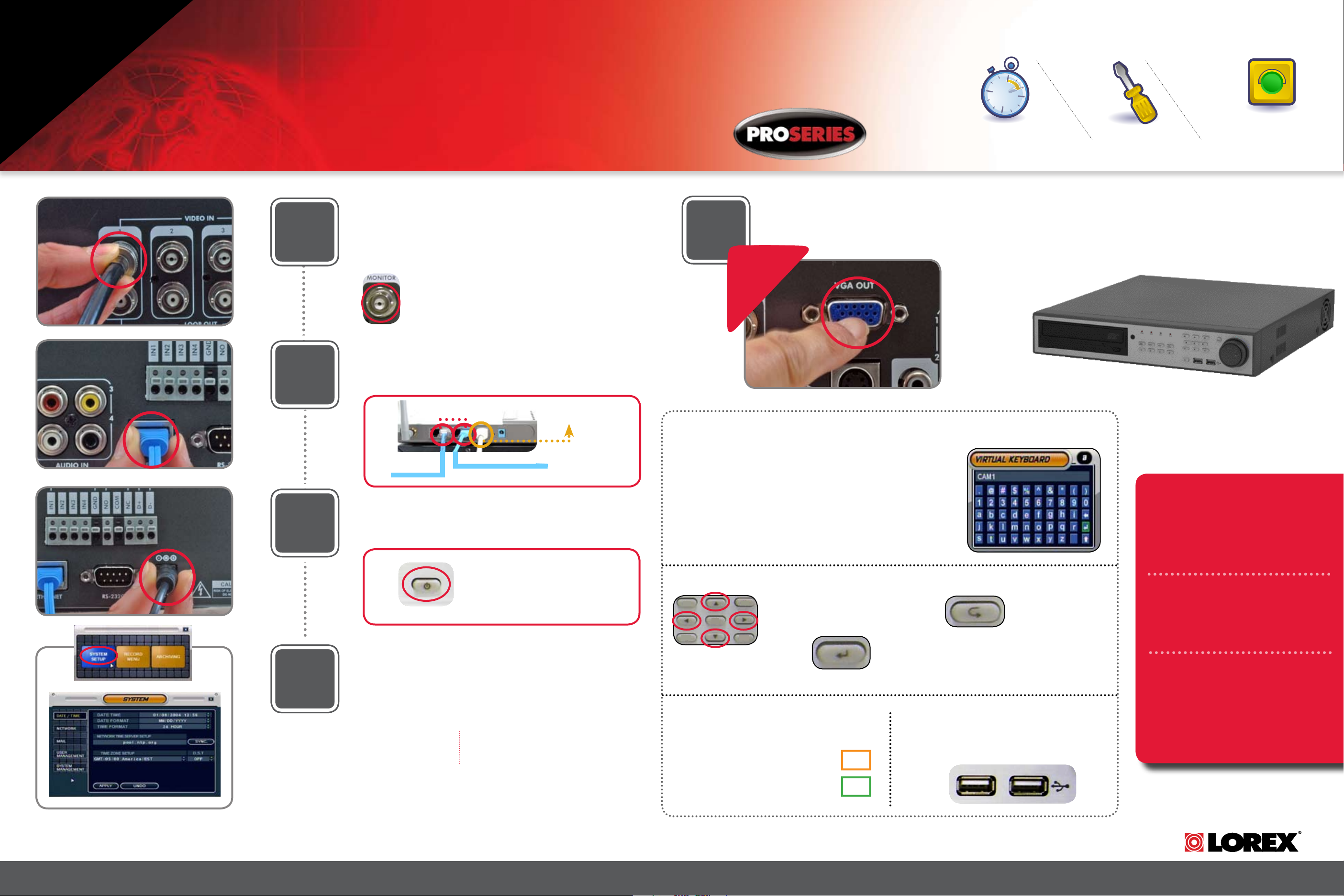
SET UP YOUR DIGITAL VIDEO RECORDER FIRST
Connect Cameras & Monitor (not included) to the DVR:
Connect the first camera to the CH1 input. Follow the same steps
to connect the additional cameras*.
1
2
* NOTE: Test the cameras prior to selecting a permanent mounting
location by temporarily connecting the Cameras and Cables to
your DVR.
Connect a CCTV monitor to the Monitor OUT (Composite
OUT) port to view camera images.
Connect Ethernet Cable:
Connect one end of the ethernet cable to one of the router’s (not
included) LAN PORTS and the other end to DVR’s Network Port
located at the back of the DVR. See picture below showing a
generic LAN/WAN connection.
5
Under 10 Minutes*
* Installation time may vary based
on application and camera cabling
Connect PC Monitor (not included) to DVR VGA Output:
To view the video from your DVR on a PC monitor, connect the
VGA Connector Cable from the PC Monitor to the VGA Port located
at the back of the DVR.
OPTIONAL
Hand Tools
Digital Video Recorder*
Plug & Play connectors,
On screen set up
LAN (LOCAL AREA NETWORK)
BACK OF THE ROUTER
TO YOUR MONITOR
TO YOUR COMPUTER
WAN (WIDE
AREA NETWORK)
Connect Power Cable:
Connect one end of the Power cable to the DVR, the other end to
an electrical outlet. This unit powers ON once it is plugged in to the
3
power outlet.
PUSH THE POWER
BUTTON TO TURN
ON THE DVR
DVR FRONT PANEL - POWER BUTTON
Set the Time and Date***:
Click the MENU button from the front panel of the DVR (or the
remote control) to enter SYSTEM SETUP and press ENTER to go to
4
Congratulations! You have completed STEP 1 successfully. Your DVR is now
ready to use. Refer to the owner’s manual to learn how to record, playback,
use the search features and all other features available with this system.
Refer to Step 3 for Setting Up Remote Security Monitoring.
MAIN MENU. From the MAIN MENU Scroll down to SYSTEM and
press ENTER to go to the DATE/TIME MENU. Press ENTER while on
DATE/TIME MENU to activate menu options.
MAKE SURE THAT
THE DATE AND TIME
ARE SET PRIOR TO
RECORDING!
*** Note: If the Date/Time is
set into the past, a message will
appear warning that Overlapped
date(s) will be erased.
NAVIGATION CONTROLS:
Virtual Keyboard Control:
The Virtual Keyboard control becomes available when keyboard input
(A~Z, 0~9) is needed for entering information such as Names,
Network Information, etc.
• Navigate using the arrow keys on the Front Panel or Remote Control.
• Use the ENTER key to choose the letters and numbers.
• Select the APPLY button once the setup is completed.
DVR Menu - Navigation Controls:
Navigation Controls:
Move UP/DOWN/
LEFT/RIGHT
Enter Button: Press
this button to select
and change the
values in a menu
option
Active Option Indicator:
Orange Highlight - Indicates that the option
is in active editing mode.
Green Highlight - Indicates that the option
is available for editing. Once the option is
highlighted, press the ENTER key to edit
the option (hightlight changes to Orange).
USB Ports:
Provides connection ports for USB Flash Drives
(thumbsticks), USB Hard Drives and Optional
Mouse (not included).
Return Button: Complete
modifications of a menu
option; exit a menu
BROADBAND ROUTER AND
COMPUTERS ARE REQUIRED (FOR
LOCAL AND REMOTE MONITORING),
NOT INCLUDED.
FOR DETAILED SETUP INFORMATION,
PLEASE REFER TO YOUR USER’S
MANUAL.
*CHANNEL/ PORT CONFIGURATION
AND HDD (HARD DISK DRIVE)
CAPACITY MAY VARY BY MODEL.
CHECK YOUR PACKAGE FOR SPECIFIC
CONTENT INFORMATION.
Information in this document is subject to change w itho ut notice. As our products are sub ject to continuous improvement, Lorex T echnolo gy INC . and our subsidiaries r eserve the right to mo dify product des ign, specifications and prices, without notice and without incurring any obl ig ation. E&OE © 2007 LOREX . All rights r eserved.
L500 Series Quick Start Guide_R1 Page 1
www.lorexcctv.com
Page 2
Router
Hi Speed
over 60 minutes
Hi Speed
over 60 minutes
BASIC INSTALLATION GUIDE
STEP 2
SET UP LOCAL VIEWING ON YOUR PC
Your DVR must be connected to a Router prior to powering it ON
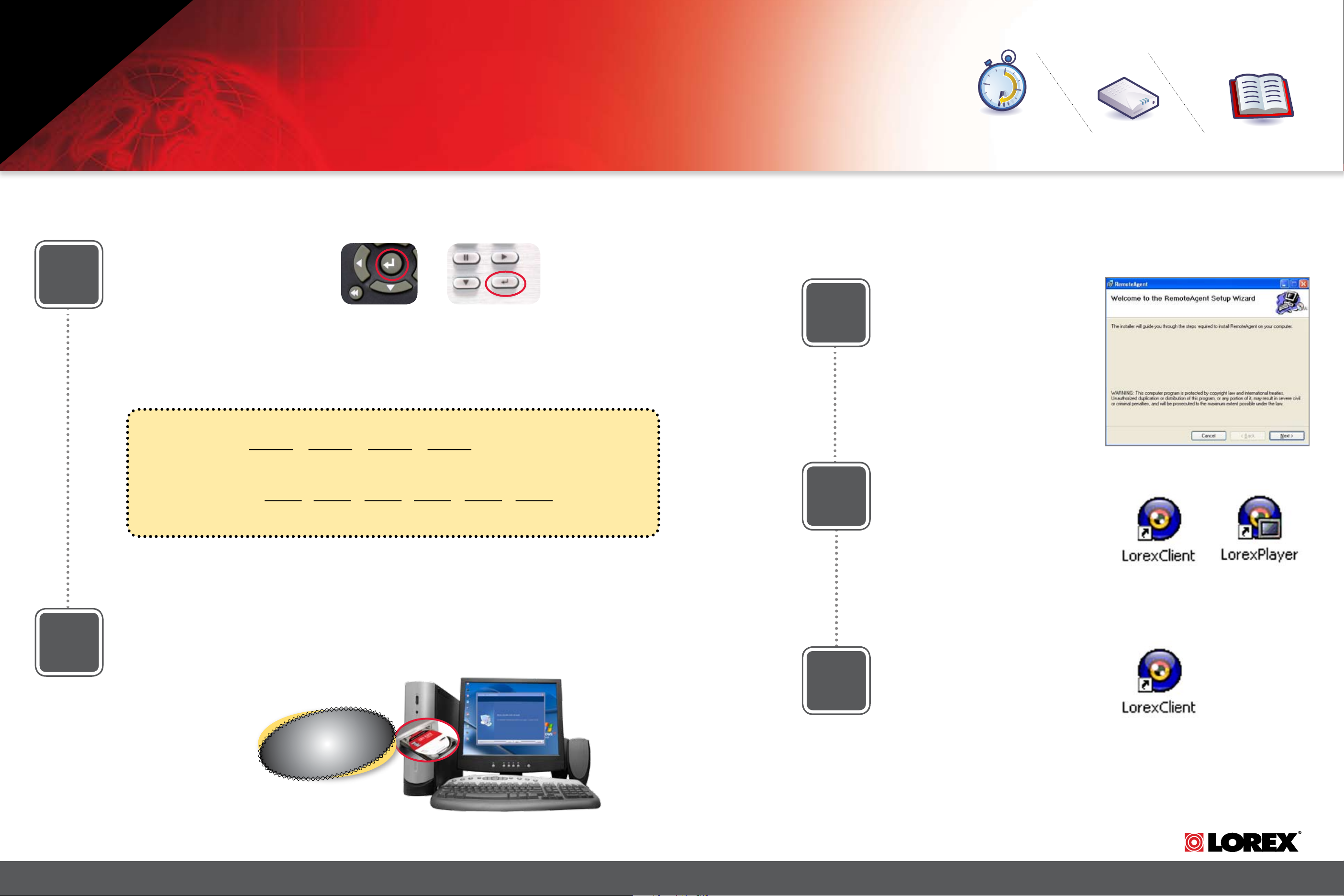
Retrieve System Information:
To retrieve the System Information,
1
press the ENTER button on the Remote
Control (ensure batteries are inserted)
(OR) Press the ENTER button on the
front panel of the DVR (please check
the user’s manual for MENU steps).
REMOTE CONTROL
DVR FRONT PANEL - ENTER BUTTON
3
Time Skills - Intermediate
Under 30 Minutes*
* Installation time may vary based
on application
Lorex Client Software:
(on your Local Computer)
Follow the installation screens to
complete Lorex Client Software installation.
Hardware
Computer & Router*
* Minimum System Requirement: Windows XP, Pentium IV, 256MB Ram
(512MB Recommended), 200MB Storage, Internet, DSL or Cable Modem
Plug & Play connectors,
On screen set up
2
Record the IP and MAC Addresses in the section below:
IP ADDRESS : . . .
MAC ADDRESS : : : : : :
(needed to register for DDNS)
Install Software:
(on your Local Computer)
Insert the Lorex Client Software CD
into your local computer’s CD ROM
drive and proceed with installation.
4
5
Lorex Client Software:
(on your Local Computer)
Close the CD Menu Screen. A Lorex
Client icon and a Lorex Player icon
will appear on your desktop.
Run the Lorex Client Software:
(on your Local Computer)
Double-click the Lorex Client software
icon on your desktop to run the program.
L500 Series Quick Start Guide_R1 Page 2
On your
Local Computer
COMPUTER - NOT INCLUDED
www.lorexcctv.com
Page 3
Continued
STEP 2
SET UP LOCAL VIEWING ON YOUR PC
H O M E & B U S I N E S S S E C U R I T Y
Basic Installation Guide
Set-up:
(on your Local Computer)
6
7
Click the Setup icon from the Lorex
Client Software Screen
SET-UP BUTTON
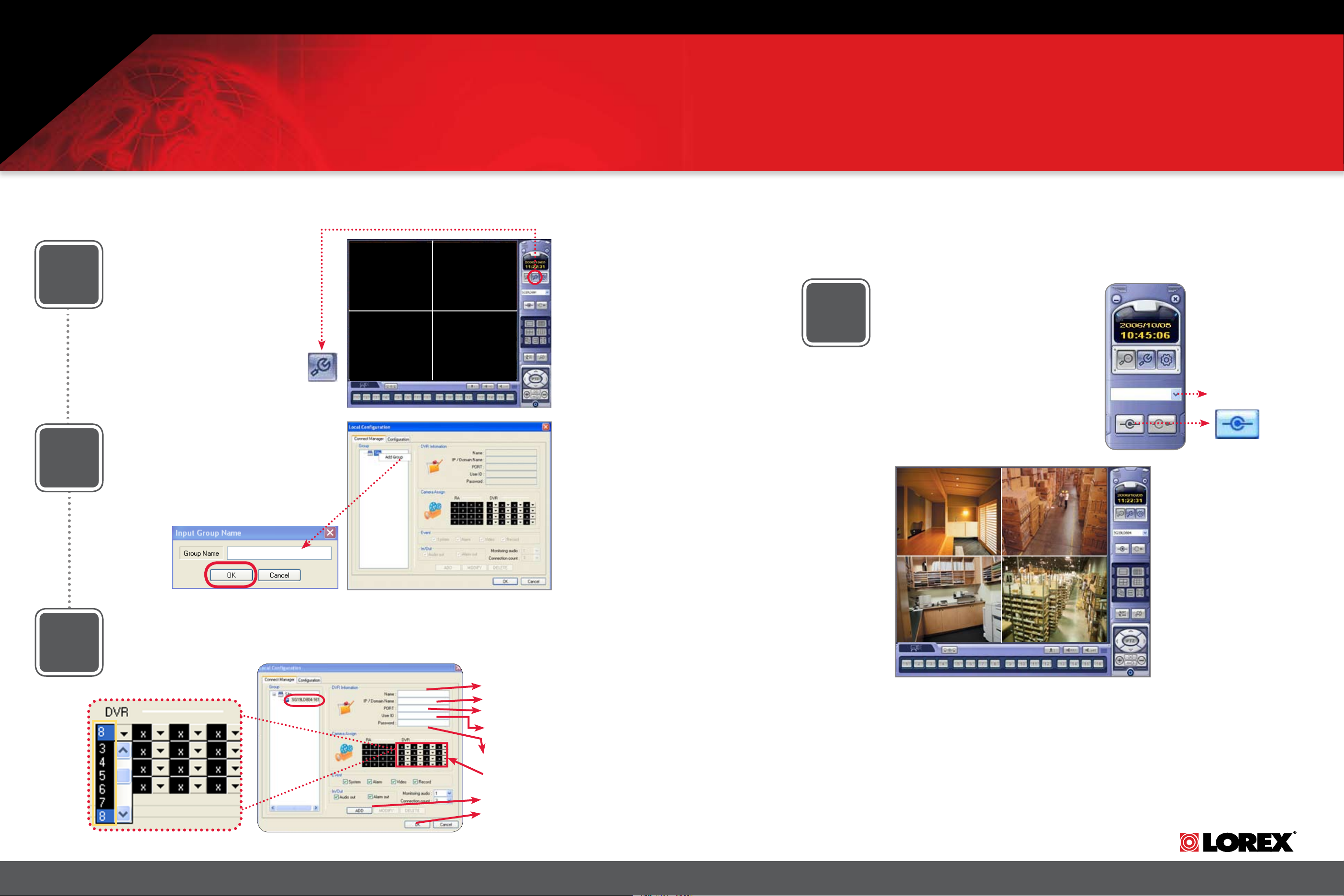
Add ‘Group’:
(on your Local Computer)
Click on the SITE listing on the Left Panel,
and Right Click to ‘ADD GROUP’.
Enter a name for the GROUP, and click OK.
OFFICE
9
Lorex Client Software - Local
Configuration:
(on your Local Computer)
From the Lorex Client Software - Local
Configuration screen (as shown in Step
7), select the new Group you created
using the drop down menu (1) and press
the CONNECT button (2) to connect to
the LOCAL LIVE site.
1
2
CONNECT BUTTON
Enter Setup Information:
(on your Local Computer)
8
Select the GROUP you created and
enter SETUP information.
6
Camera Selection Dropdown Menu
L500 Series Quick Start Guide_R1 Page 3
System
1
192.168.0.150
6100
ADMIN
** **
7
2
3
4
5
6
8
1. Enter a Name for the System
2. Enter the IP Address recorded in Step 2-1
3. Enter the DVR TCP/IP port (6100 by default)
4. Enter the User ID (ADMIN by default), max. 5
characters
5. Enter the Admin Password (1234 by default)
* User ID and Password are case sensitive
6. Add cameras using the dropdown menus to assign
camera positions
7. Click ADD to add the System Location
8. Click OK
LOCAL LIVE SITE
www.lorexcctv.com
Page 4

Hi Speed
over 60 minutes
Hi Speed
over 60 minutes
STEP 3
REMOTE VIEWING INSTALLATION GUIDE
Time Hardware Skills - Advanced
SET UP INTERNET REMOTE SECURITY MONITORING
Port Forward Your Router:
1
2
Port forward your router first before proceeding with the set-up (you must forward
web port 80 and TCP/IP Port 6100).
All routers are different. To port forward your router, please refer to your router’s
user’s manual.
A Router Configuration Guide is available on your Lorex Client Software CD and also
on our website in the Consumer Guide’s section.
DDNS Set-up:
Open your web browser (Interet Explorer by default) and enter
http://ddns.strategicvista.net in the address
bar.
http://ddns.strategicvista.net
4
5
60 Minutes
* Installation time may vary based
on application
Complete New Account
Information:
1. FOR PRODUCT LICENSE select the
L500 Series option from the drop down
menu.
2. FOR PRODUCT CODE enter the
DVR’s MAC address (recorded in step 2,
section 1).
3. FOR URL REQUEST enter a unique
URL name (e.g. tomsmith1). Note: URL
name should not be more than 15 characters.
Registration Email:
An automated REGISTRATION CONFIRMATION EMAIL will be sent to your
email. Print and Save this confirmation.
You will need this information to access
your System remotely.
Computer & Router*
* Minimum System Requirement: Windows XP, Pentium IV, 256MB Ram
(512MB Recommended), 200MB Storage, Internet, DSL or Cable Modem
1
Basic Computer Skills,
Router Port Forwarding
2
3
Service Provider: dns1.strategicvista.net
Domain Name: tomsmith.strategicvista.net
User ID: tomsmith1
Password: (your password)
Create Account:
From the http://ddns.strategicvista.net
3
L500 Series Quick Start Guide_R1 Page 4
website, click the CREATE ACCOUNT
option.
Create Account
6
Enter DDNS Set-up on your
DVR:
Enter DDNS SET option on your DVR by
pressing the MENU button on the front
panel of your DVR (or Remote Control).
Select the SYSTEM SETUP and press
ENTER. Scroll down to SYSTEM and
press ENTER. Scroll down to NETWORK
option and press ENTER.
DVR FRONT PANEL - SETUP BUTTON
www.lorexcctv.com
Page 5

Continued
STEP 3
SET UP INTERNET REMOTE SECURITY MONITORING
7
Enable DDNS Settings:
On the NETWORK menu, use the
DOWN arrow key to navigate to
DDNS. Highlight DDNS checkbox
by pressing ENTER and press the
UP arrow key to put a check mark
in the DDNS checkbox. Press
ENTER to accept settings.
10
H O M E & B U S I N E S S S E C U R I T Y
Lorex Client Software:
(on your Remote Computer*)
Follow the installation screens to
complete Lorex Client Software
installation.
8
9
Set the DDNS Settings:
1. Scroll down to the DDNS SERVER within the
NETWORK menu and press ENTER.
2. Enter the USER ID sent to you in the
REGISTRATION CONFIRMATION EMAIL.
3. Enter the DOMAIN NAME sent to you in the
REGISTRATION CONFIRMATION EMAIL
(i.e.tomsmith.strategicvista.net) leaving out the
.strategicvista.net part of the URL.
4. Enter your PASSWORD (from the DDNS
Registration Email sent to you).
5. Click the DDNS Status button - A SUCCESS
message will appear if the settings are correct.
6. Scroll to OK button and press ENTER to accept.
7. On the SYSTEM menu screen scroll down to APPLY
and press ENTER.
8. The system will now ask you to RESTART.
Click OK.
Install Software:
(on your Remote Computer*)
Insert the Lorex Client Software CD into
your remote computer’s CD ROM drive
and proceed with installation.
LOREX
tomsmith1
tomsmith
****
SUCCESS
11
12
Lorex Client Software:
(on your Remote Computer*)
Close the CD Menu Screen. A Lorex
Client icon and a Lorex Player icon will
appear on your desktop.
Run the Lorex Client Software:
(on your Remote Computer*)
Double-click the Lorex Client icon on
your desktop to run the program.
Remote Computer*
*For viewing your system from a remote location
L500 Series Quick Start Guide_R1 Page 5
On your
COMPUTER - NOT INCLUDED
www.lorexcctv.com
Page 6

Continued
STEP 3
SET UP INTERNET REMOTE SECURITY MONITORING
H O M E & B U S I N E S S S E C U R I T Y
Set-up:
(on your Remote Computer*)
13
14
Click the Setup icon from the Lorex
Client Software Screen
SET-UP BUTTON
Add ‘Group’:
(on your Remote Computer*)
Click on the SITE listing on the Left
Panel, and Right Click to ‘ADD GROUP’.
Enter a name for the GROUP, and click
OK.
OFFICE
16
Lorex Client Software - Local
Configuration:
(on your Remote Computer*)
From the Lorex Client Software - Local
Configuration screen (as shown in Step
13), select the new Group you created
using the drop down menu (1) and press
the CONNECT button (2) to connect to
the REMOTE* LIVE site.
1
2
CONNECT BUTTON
Enter Setup Information:
(on your Remote Computer*)
15
6
Camera Selection Dropdown Menu
L500 Series Quick Start Guide_R1 Page 6
System
1
tomsmith.strategicvista.net
2
6100
3
ADMIN
4
** **
5
6
7
8
1. Enter a Name for the System
2. Enter the DDNS DOMAIN NAME from the
Registration Email sent to you.
3. Enter the DVR TCP/IP port (6100 by default)
4. Enter the User ID (ADMIN by default), max. 5
characters
5. Enter the Admin Password (1234 by default)
* User ID and Password are case sensitive
6. Add cameras using the dropdown menus to assign
camera positions
7. Click ADD to add the System Location
8. Click OK
*For viewing your system from a remote location
REMOTE* LIVE SITE
For other remote access viewing
features, please consult the Lorex
Client Software Manual.
www.lorexcctv.com
Page 7

THIS PAGE IS INTENTIONALLY LEFT BLANK.
L500 Series Quick Start Guide_R1 Page 7
www.lorexcctv.com
Page 8

IT’S ALL ON THE WEB
www.lorexcctv.com
For detailed setup information, please refer to your User’s Manual. For additional
information about determining your IP address, configuring your router, and
port forwarding, please visit our website www.lorexcctv.com/support and click
Consumer Guides Section or view guides from the CD included with your system.
Email Support: support@lorexcorp.com
Toll Free Technical Support - North America: 1-888-42 LOREX (1-888-425-6739)
Toll Free Technical Support - International (outside of North America): 00-800-425-6739-0
Lorex International Website - www.lorexinternational.com
Product Information Software/Hardware
L500 Series Quick Start Guide_R1 Page 8
Product Documentation
Updates & Ugrades
Specification Sheet
User’s Manual
Lorex Client Software Manual
Quick Start Guide
Portforwarding Guide
Basics of Remote Video
Access Guide
www.lorexcctv.com
 Loading...