

Page 1
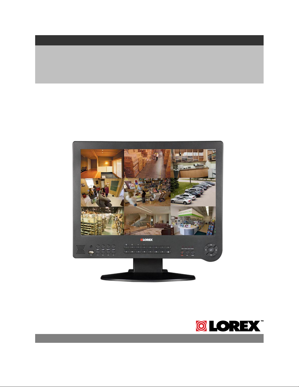
19” WIDE SCREEN LCD MONITOR
WITH INTEGRATED DIGITAL VIDEO RECORDER
Instruction Manual
English, French, and Spanish Version 2.0
Version angliase, française, et espagnol 2.0
Versión inglesa, francesa, y española 2.0
MODELS:
L19WD Series
Includes L19WD800 & L19WD1600
Copyright © 2008 Lorex Technology Inc.
www.lorexcctv.com
Page 2
Thank you for purchasing this product. Lorex is committed to providing our customers with a
high quality, reliable security solution.
This manual refers to the following models:
To learn more about this system and our complete range of accessory products, along
Manuals, Quick Start Guides, and Firmware, please visit our website at:
• L19WD800 Series (8-channel)
• L19WD1600 Series (16-channel)
http://www.lorexcctv.com
CAUTION
RISK OF ELECTRIC SHOCK
DO NOT OPEN
CAUTION: TO REDUCE THE RICK OF ELECTRIC SHOCK
REFER SERVICING TO QUALIFIED SERVICE PERSONNEL.
WARNING: TO PREVENT FIRE OR SHOCK HAZARD, DO NOT
EXPOSE THIS UNIT TO RAIN OR MOISTURE.
CAUTION: TO PREVENT ELECTRIC SHOCK, MATCH WIDE BLADE
OF THE PLUG TO THE WIDE SLOT AND FULLY INSERT.
DO NOT REMOVE COVER (OR BACK).
NO USER SERVICABLE PARTS INSIDE.
The lightning flash with arrowhead symbol, within an
equilateral triangle, is intended to alert the user to the
presence of uninsulated “dangerous voltage” within the
products ‘ enclosure that may be of sufficient magnitude
to constitute a risk of electric shock
The exclamation point within an equilateral triangle is
intended to alert the user to the presence of important
operating and maintenance (servicing) instructions in the
literature accompanying the appliance.
2
Page 3
p
L19WD Series
Important Safeguards
In addition to the careful attention devoted to quality standards in the manufacture process of your video
product, safety is a major factor in the design of every instrument. However, safety is your responsibility
too. This sheet lists important information that will help to assure your enjoyment and proper use of the
video product and accessory equipment. Please read them carefully before operating and using your
video product.
Installation
1. Read and Follow Instructions - All the safety
and operating instructions should be read
before the video product is operated. Follow all
operating instructions.
2. Retain Instructions - The safety and operating
instructions should be retained for future
reference.
3. Heed Warnings - Comply with all warnings on
the video product and in the operating
instructions.
4. Polarization - Do not defeat the safety purpose
of the polarized or grounding-type plug.
o A polarized plug has two blades with
one wider than the other.
o A grounding type plug has two
blades and a third grounding prong.
o The wide blade or the third prong is
provided for your safety.
o If the provided plug does not fit into
your outlet, consult an electrician for
lacement of the obsolete outlet
re
5. Power Sources - This video product should be
operated only from the type of power source
indicated on the marking label. If you are not
sure of the type of power supply to your
location, consult your video dealer or local
power company. For video products intended to
operate from battery power, or other sources,
refer to the operating instructions.
6. Overloading - Do not overload wall outlets of
extension cords as this can result in the risk of
fire or electric shock. Overloaded AC outlets,
extension cords, frayed power cords, damaged
or cracked wire insulation, and broken plugs are
dangerous. They may result in a shock or fire
hazard. Periodically examine the cord, and if its
appearance indicates damage or deteriorated
insulation, have it replaced by your service
technician.
7. Power-Cord Protection - Power supply cords
should be routed so that they are not likely to be
walked on or pinched by items placed upon or
against them, paying particular attention to
cords at plugs, convenience receptacles, and
the point where they exit from the video product.
8. Ventilation - Slots and openings in the case
are provided for ventilation to ensure reliable
operation of the video product and to protect
it from overheating. These openings must not
be blocked or covered. The openings should
never be blocked by placing the video
equipment on a bed, sofa, rug, or other
similar surface. This video product should
never be placed near or over a radiator or
heat register. This video product should not
be placed in a built-in installation such as a
bookcase or rack unless proper ventilation is
provided or the video product manufacturer’s
instructions have been followed.
9. Attachments - Do not use attachments
unless recommended by the video product
manufacturer as they may cause a hazard.
10. Water and Moisture - Do not use this video
product near water. For example, near a bath
tub, wash bowl, kitchen sink or laundry tub, in
a wet basement, near a swimming pool and
the like.
Caution: Maintain electrical safety. Power line
operated equipment or accessories
connected to this unit should bear the UL
listing mark of CSA certification mark on the
accessory itself and should not be modified
so as to defeat the safety features. This will
help avoid any potential hazard from electrical
shock or fire. If in doubt, contact qualified
service personnel.
11. Accessories - Do not place this video
equipment on an unstable cart, stand, tripod,
or table.
The video equipment may fall,
causing serious damage to the
video product. Use this video
product only with a cart, stand,
tripod, bracket, or table
recommended by the
manufacturer or sold with the
video product.
Any mounting of the product should follow
the manufacturer’s instructions and use a
mounting accessory recommended by the
manufacturer.
3
Page 4

Important Safeguards
Service
13. Servicing - Do not attempt to service this
video equipment yourself as opening or
removing covers may expose you to
dangerous voltage or other hazards. Refer all
servicing to qualified service personnel.
14. Conditions Requiring Service - Unplug this
video product from the wall outlet and refer
servicing to qualified service personnel under
the following conditions.
A. When the power supply cord or plug is
damaged.
B. If liquid has been spilled or objects have
fallen into the video product.
C. If the video product has been exposed to
rain or water.
D. If the video product does not operate
normally by following the operating
instructions. Adjust only those controls
that are covered by the operating
instructions. Improper adjustment of
other controls may result in damage and
will often require extensive work by a
qualified technician to restore the video
product to its normal operation.
E. If the video product has been dropped or
the cabinet has been damaged.
F. When the video product exhibits a
distinct change in performance. This
15. Replacement Parts - When replacement
16. Safety Check - Upon completion of any
17. Wall or Ceiling Mounting - The cameras
18. Heat - The product should be situated away
indicates a need for service.
parts are required, have the service
technician verify that the replacements used
have the same safety characteristics as the
original parts. Use of replacements specified
by the video product manufacturer can
prevent fire, electric shock or other hazards.
service or repairs to this video product, ask
the service technician to perform safety
checks recommended by the manufacturer to
determine that the video product is in safe
operating condition.
provided with this system should be mounted
to a wall or ceiling only as instructed in this
guide, using the provided mounting brackets.
from heat sources such as radiators, heat
registers, stoves, or other products (including
amplifiers) that produce heat.
Use
19. Cleaning - Unplug the video product from the
wall outlet before cleaning. Do not use liquid
cleaners or aerosol cleaners. Use a damp
cloth for cleaning.
20. Product and Cart Combination - Video and
cart combination should be moved with care.
Quick stops, excessive force, and uneven
surfaces may cause the video product and
car combination to overturn
21. Object and Liquid Entry - Never push
objects for any kind into this video product
through openings as they may touch
dangerous voltage points or “short-out” parts
that could result in a fire or electric shock.
Never spill liquid of any kind on the video
product
22. Lightning - For added protection for this
video product during a lightning storm, or
when it is left unattended and unused for long
periods of time, unplug it from the wall outlet
and disconnect the antenna or cable system.
This will prevent damage to the video product
due to lightning and power line surges. The
manufacturer’s instructions and use a
mounting accessory recommended by the
manufacturer.
4
Page 5

L19WD Series
General Precautions
1. All warnings and instructions of this manual should be followed
2. Remove the plug from the outlet before cleaning. Do not use liquid aerosol detergents. Use a water
dampened cloth for cleaning
3. Do not use this unit in humid or wet places
4. Keep enough space around the unit for ventilation. Slots and openings in the storage cabinet should
not be blocked
5. During lightning storms, or when the unit is not used for a long time, disconnect the power supply,
antenna, and cables to protect the unit from electrical surge
FCC CLASS B NOTICE
Note:
This equipment has been tested and found to comply with the limits for a Class B digital device,
pursuant to Part 15 of the FCC Rules. These limits are designed to provide reasonable protection
against harmful interference in a residential installation. This equipment generates, uses, and can
radiate radio frequency energy and, if not in-stalled and used in accordance with the instruction, may
cause harmful interference to radio communications.
However, there is no guarantee that interference will not occur in a particular installation. If this
equipment does cause harmful interference to radio or television reception (which can be determined
by turning the equipment on and off), the user is encouraged to try to correct the interference by one
or more of the following measures:
o Reorient or relocate the receiving antenna
o Increase the separation between the equipment and receiver
o Connect the equipment into an outlet on a circuit different from that to which the receiver
is connected
o Consult the dealer or an experienced radio or television technician for assistance
This equipment has been certified and found to comply with the limits regulated by FCC, EMC, and
LVD. Therefore, it is designated to provide reasonable protection against interference and will not
cause interference with other appliance usage.
However, it is imperative that the user follows this manual' guidelines to avoid improper usage which
may result in damage to the unit, electrical shock and fire hazard injury
In order to improve the feature functions and quality of this product, the specifications are subject to
change without notice from time to time.
LOREX TECHNOLOGY INC.
www.lorexcctv.com
5
Page 6

L19WD800 Series Features
L19WD800 Series Features
• High resolution 19” LCD widescreen monitor with integrated 8-channel digital video recorder
• Pentaplex operation allows Viewing, Recording, Playback, and Backup the system
simultaneously
• Real-Time Recording: 240/480 FPS @ CIF Resolution (8/16ch)
• H.264 video compression technology provides longer recording time and improved network
transmission speed
• Internet Remote Monitoring (software included) and Web Browser access
• Mouse-driven navigation (mouse included) and Graphical User Interface
• Large Capacity Security Certified Hard Drive pre-installed and expandable up to
1 Terabyte (TB)*†
• USB port for backup and convenient transfer of critical data
• Message Master software (included) allows you to send text and pictures from a remote location
• Installer friendly – Easy Quick Start Guide and Toll Free Tech Support
Connections:
• Up to 8 cameras (16 cameras on L19WD1600)
• BNC Cable Connectors
• 6-pin DIN connectors (only on L19WD800)
• Audio Input & Output
* 1 TB = 1000 Gigabytes (GB).
† Recording capacity may vary based on recording resolution and quality, lighting conditions, and movement
6
Page 7

L19WD Series
Table of Contents
Getting Started ..............................................................................................................................................8
Front Panel.................................................................................................................................................... 9
Front Panel (cont’d)..................................................................................................................................... 10
Rear Panel ..................................................................................................................................................12
Camera Installation ..................................................................................................................................... 13
Installation Warnings ............................................................................................................................... 13
Camera Stand Installation ....................................................................................................................... 13
Connecting BNC Cameras..........................................................................................................................14
Camera Connection Diagram.................................................................................................................. 14
Connecting DIN Cameras*..........................................................................................................................15
Mouse Control............................................................................................................................................. 16
Using the mouse...................................................................................................................................... 16
Function Bar ............................................................................................................................................ 17
Remote Control ...........................................................................................................................................19
Menu Navigation Control & Tips ................................................................................................................. 20
System Main Menu .....................................................................................................................................21
System Control Panel Icons .................................................................................................................... 22
Starting up the system ................................................................................................................................23
System login ............................................................................................................................................23
Setting the Date & Time ..........................................................................................................................24
Turning the monitor off ............................................................................................................................25
Display Modes.............................................................................................................................................27
Live Mode ................................................................................................................................................27
Full-Screen, Quad, & Split Views ............................................................................................................ 28
Playback ..................................................................................................................................................29
Search Mode ...........................................................................................................................................30
Using the System ........................................................................................................................................32
Configuration ........................................................................................................................................... 32
Display..................................................................................................................................................... 37
HDD Management...................................................................................................................................40
Camera.................................................................................................................................................... 41
Record .....................................................................................................................................................45
Backup / Upgrade.................................................................................................................................... 47
Network....................................................................................................................................................48
Language ....................................................................................................................................................52
Appendix 1: System Specifications.............................................................................................................53
Appendix 2: Lorex Client Software Requirements ......................................................................................55
Appendix 3: Setting Up Remote Viewing.................................................................................................... 56
Appendix 4: Listen-In Audio ........................................................................................................................66
Appendix 5: Setting Up Motion Recording.................................................................................................. 67
Appendix 6: Using the Storage Calculator.................................................................................................. 69
Appendix 7: Replacing the Hard Drive........................................................................................................70
Appendix 8: Connecting a Spot-Out Monitor ..............................................................................................71
Appendix 9: Connecting Motion / Alarm Device..........................................................................................71
Appendix 9: Connecting Motion / Alarm Device..........................................................................................72
Appendix 10: Connecting PTZ Cameras ....................................................................................................72
Appendix 10: Connecting PTZ Cameras ....................................................................................................73
Appendix 11: Full Connectivity Diagram..................................................................................................... 74
ENG
7
Page 8
Getting Started
Getting Started
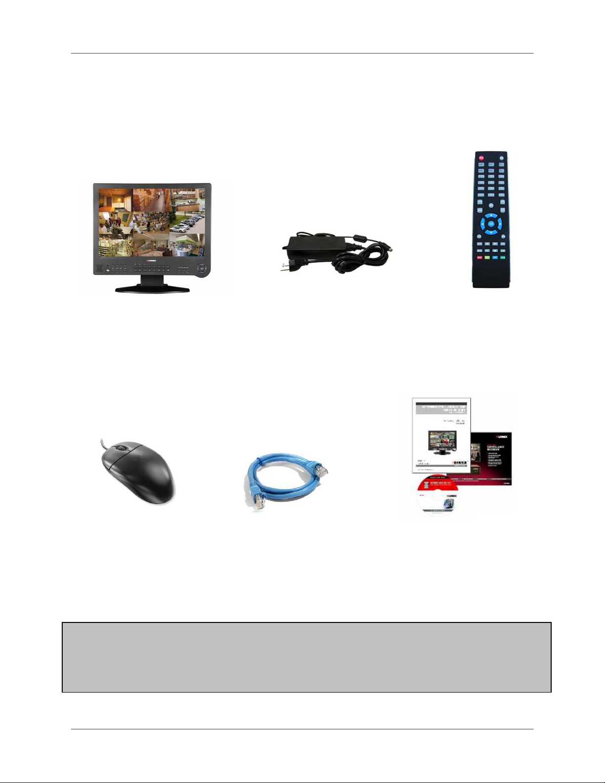
The system comes with the following components:
1 X INTEGRATED LCD DVR
SYSTEM WITH PRE-INSTALLED
HDD*
1 X MOUSE
(PS/2)
1 X POWER ADAPTOR
1 X POWER ADAPTOR CABLE
1 X ETHERNET
CABLE
1 X USERS MANUAL
1 X QUICK START GUIDE
1 X REMOTE
CONTROL
1 X SOFTWARE CD
*HARD DRIVE SIZE, NUMBER OF CHANNELS, AND CAMERA CONFIGURATION MAY VARY
BY MODEL. PLEASE REFER TO YOUR PACKAGE FOR SPECIFIC CONTENT DETAILS.
CHECK YOUR PACKAGE TO CONFIRM THAT YOU HAVE RECEIVED THE COMPLETE
8
Page 9
Basic Setup
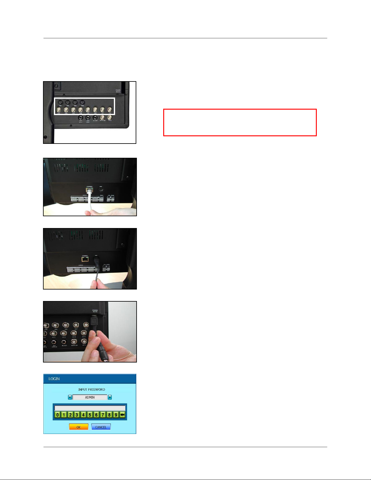
Make the following connections prior to starting the system for the first time.
1. Connect the cameras to the monitor
L19WD Series
Front Panel
Please see the Camera Installation section of this
manual for details.
ATTENTION: Test the cameras prior to permanently
mounting them by temporarily connecting the
cameras and cables to your system.
2. Connect the Ethernet cable
Connect one end of the Ethernet cable (for remote
monitoring) to the LAN port on a router (not included),
and the other end to the Ethernet port on the back of
the system.
3. Connect the mouse
Connect a PS/2 mouse to the port on the back of the
system.
4. Connect the power cable
Connect one end of the power adaptor to the monitor
and the other end to an electrical outlet.
Note: The system automatically powers on once
connected to a power source. By default, all connected
cameras are set to record in Continuous Mode when the
system is first powered on.
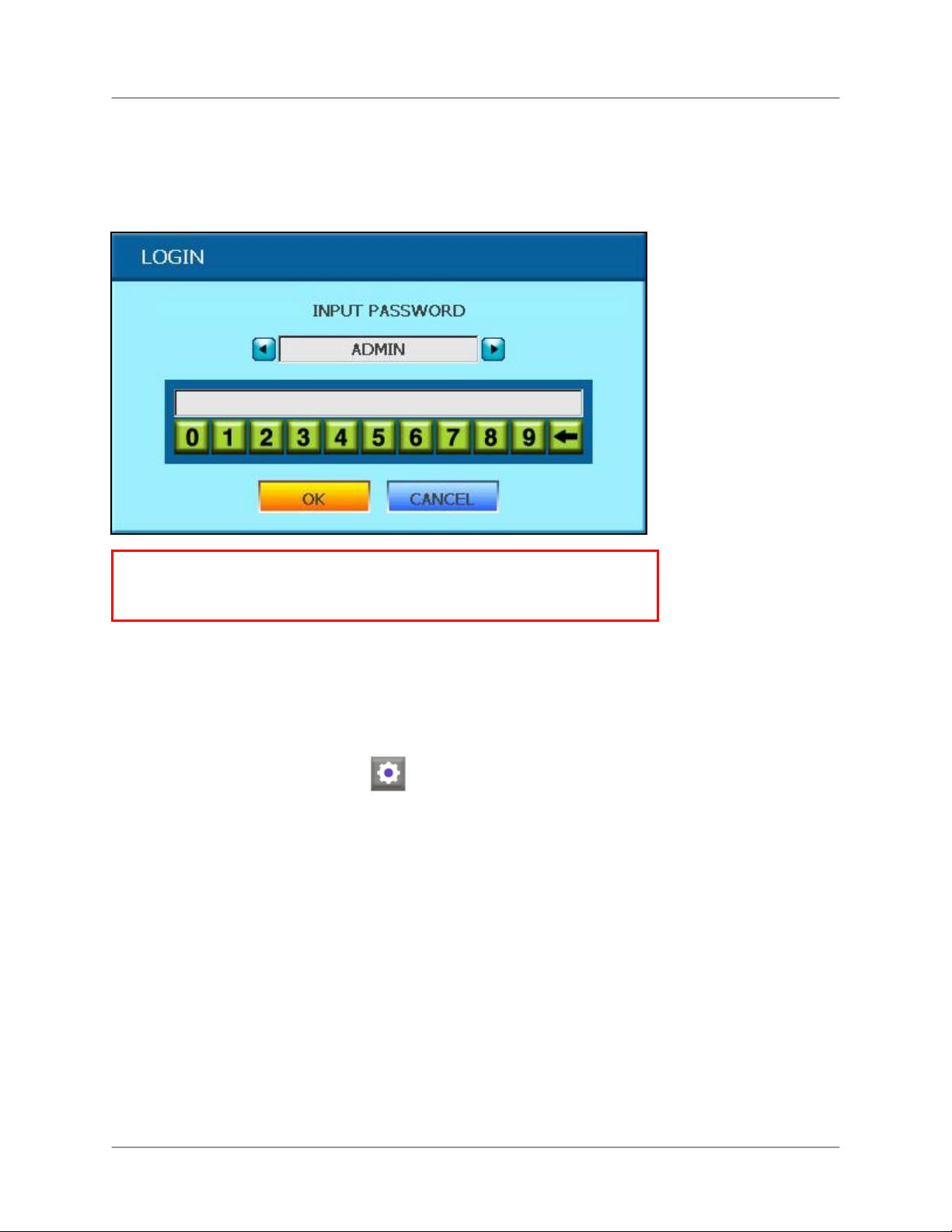
5. Login to the system
After the initial startup sequence, you will need to
login to the system. To login, leave the default user
as ADMIN. Leave the password field blank and
click OK. See the section, Starting up the System
for more details.
9
Page 10
Front Panel
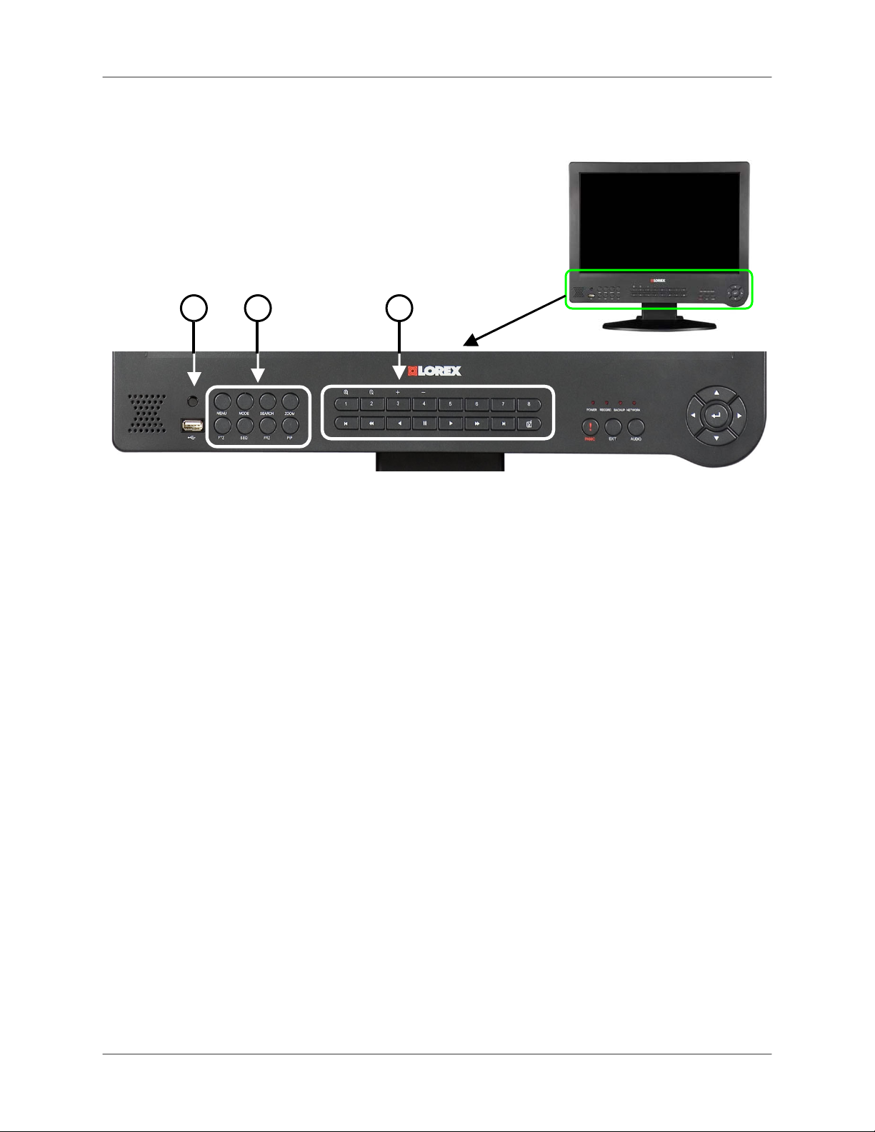
Front Panel
2 3 1
4
8-channel model shown
1. IR Sensor: Receives the infrared signal from the remote control.
2. Function Buttons: The left set of function buttons consist of the following:
• Menu: Press to enter the System Main Menu; press and hold to power off the
monitor.
• Mode: Switch between screen displays – full-screen, quad, and split-screen view.
• Search: Search for recorded video on the HDD.
• Zoom: Zoom in/out of an image using digital zoom.
• PTZ: Open the control menu for Pan, Tilt, Zoom – a PTZ camera (not included)
must be connected to the system to make use of the PTZ menu.
• SEQ: Activate sequence function in any display mode.
• FRZ: Freeze live image.
• PIP: Picture-in-Picture mode.
3. Numeric Keypad and Playback Buttons*:
• 1~8: Press to view each channel of the system in full-screen mode.
• 1+: In PTZ Mode: zoom in.
• 2-: In PTZ Mode: zoom out.
• 3+: In PTZ Mode, channel up.
• 4-: In PTZ Mode, channel down.
*Only on L19WD800. 16-button numeric keypad found on L19WD1600.
10
Page 11
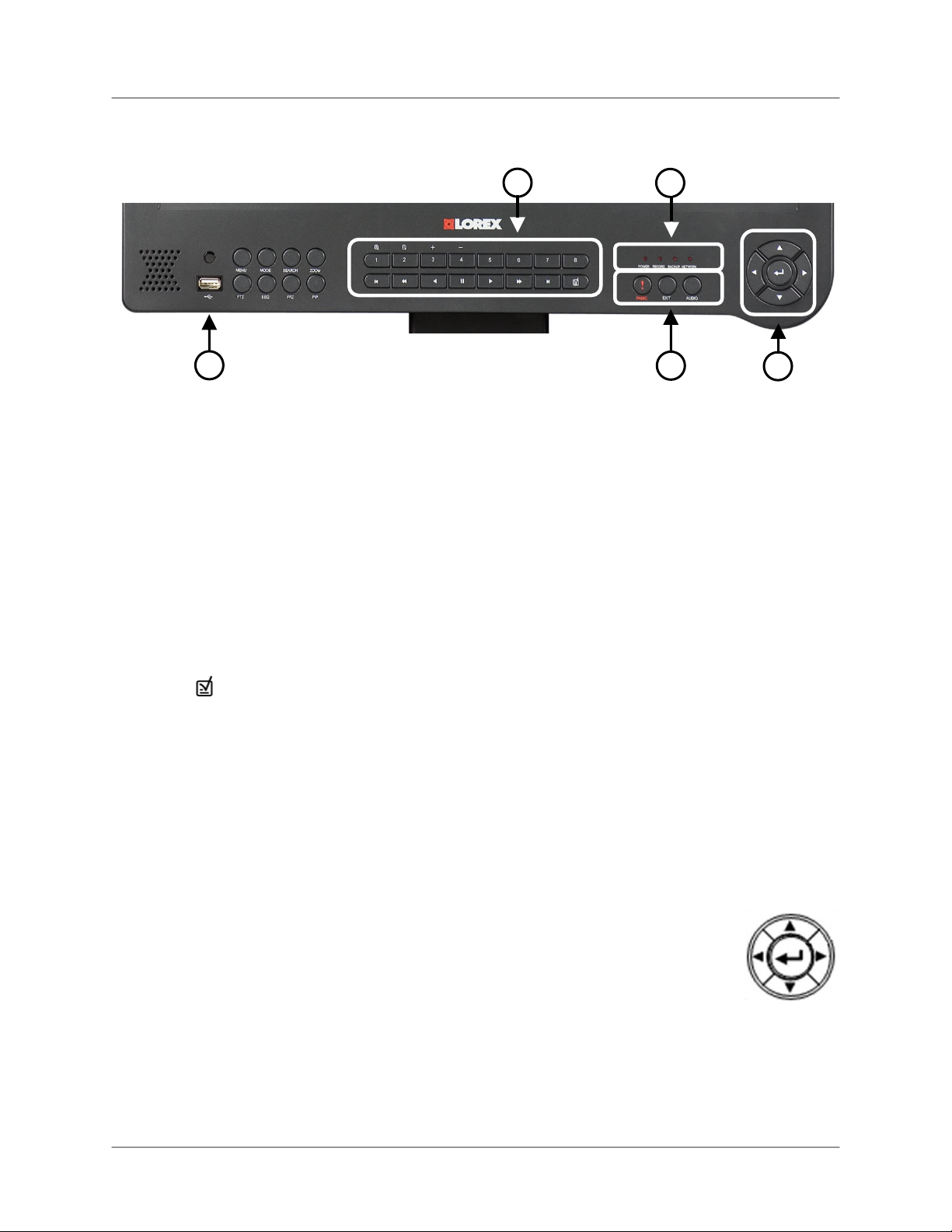
Front Panel (cont’d).
L19WD Series
3
4
5
6
3. Numeric Keypad and Playback Buttons* (cont’d):
• In Playback Mode, jump to start of recording
• Slow motion speeds in Forward Playback: 1/4, 1/8, 1/16, and 1/32;
Increase playback speed in Reverse Playback: 2X, 4X, 16X, and 32X.
• Reverse playback; in Login Menu, also used as Backspace to delete digits.
• Play
• Pause
• Stop
• Increase playback speed in Forward Playback: 2X, 4X, 16X, and 32X;
Slow motion speeds in Reverse Playback: 1/4, 1/8, 1/16, and 1/32.
• In Playback Mode, jump to end of recording
In Playback Mode, set a bookmark for future reference in Search Mode.
•
4. LED Indicator: Four lights show the status of the system: Power, Record, Backup, and
Network.
5. USB Port: USB 2.0 port for data backup and uploading firmware updates.
6. Function Buttons: The right set of function buttons consist of the following:
• Panic: In an emergency, press Panic for Continuous recording with High Quality
Video. Panic Recording overrides any active recording mode or function of the
system.
• Exit: Press to exit menus / functions or to stop playback.
• Audio: Select audio channel; mute internal speaker.
7. Navigation Arrows: Use the arrows and Enter button to select Menu
options.
• Enter:
Forward & Reverse Playback, Pause; hold to display system
information.
• Left: Increase playback speeds in Reverse playback; Slow Motion
speeds in Forward playback
• Right: Increase playback speeds in Forward playback; Slow Motion speeds in
Reverse playback
• Up: In Live mode or during playback, increase the volume of the internal speaker.
• Down: In Live mode or during playback, decrease the volume of the internal speaker.
7
11
Page 12
Rear Panel
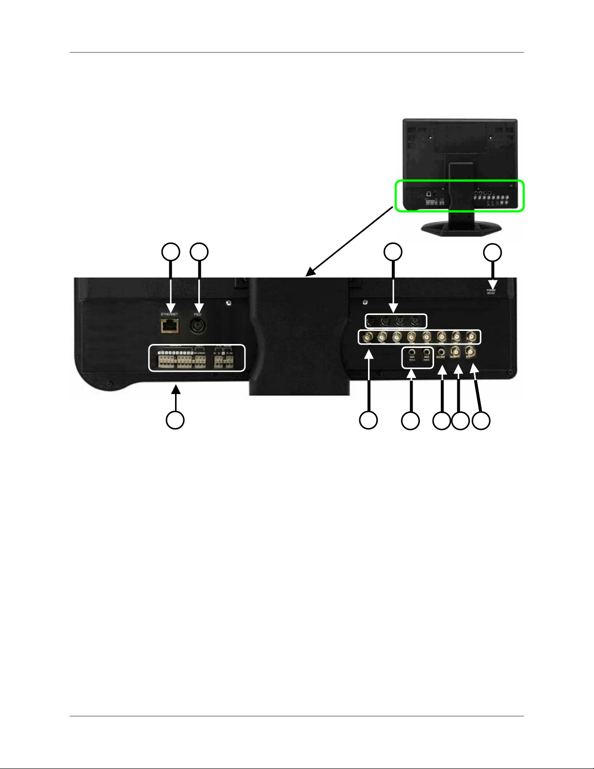
Rear Panel
2
1
3
4
5
6
7
8
10
9
1. Ethernet Port: Connects the System to a router or switch for networking purposes.
2. PS/2 Mouse: Dedicated connection for a PS/2 mouse.
3. 6-pin DIN Camera Inputs*: Channels 1~4 for 6-pin DIN cameras. Cameras with 6-pin
DIN connectors draw power from the system; additional power adaptors are not required.
4. DC Input: Connects the system to the power adaptor.
5. Relay/PTZ/RS-232 Block: These terminals send a signal to a secondary device or
control Pan, Tilt, Zoom cameras.
6. BNC Camera Inputs†: BNC video ports for channels 1-8; cameras with BNC connection
require an additional power adaptor.
7. RCA Audio Inputs (2)**: Audio inputs for channels 1~4 and channels 5~8.
8. Audio Out: Audio output port to connect to speakers, or a secondary DVR, or TV.
9. Monitor Out: Connect a secondary monitor; directly reflects the onscreen images.
10. Spot Out: Spot video output to a secondary monitor to view the active video channels in
sequence. Use in situations where the system will be in a backroom, but you want to
display images to the public, whether for theft deterrence or advertising purposes.
*6-pin DIN ports only on L19WD800
**Four audio inputs on L19WD1600.
†16 BNC ports and 16 alarm ports available on L19WD1600.
12
Page 13
L19WD Series
Camera Installation
Before you install the camera*, carefully plan where and how it will be positioned, and where
you will route the cable that connects the camera to the DVR.
Installation Warnings
• Select a location for the camera that provides a clear view of the area you want to
monitor, which is free from dust, and is not in line-of-sight to a strong light source or
direct sunlight.
• Plan the cables’ route so that it is not close to power or telephone lines, transformers,
microwave ovens or other electrical equipment that could interfere with the DVR.
• Select a location for the camera that has an ambient temperature between 14°F~113°F
(-10°C~45°C)
• If you plan to install the camera in a location that has conditions not recommended in
this manual, consult with a professional installer and consider use of a separate camera
cover or housing
• Before starting permanent installation, have another person hold the camera for you
while you verify its performance by observing the image on a monitor.
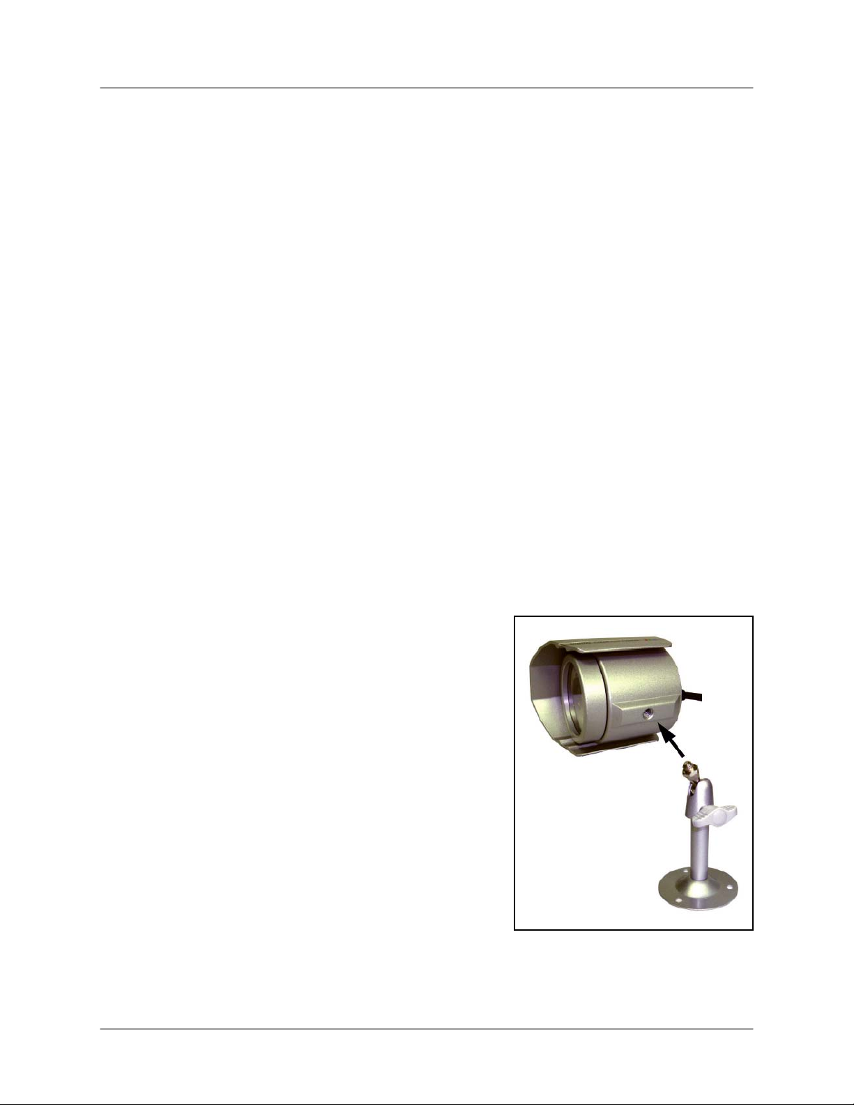
Camera Stand Installation
1. Attach the pedestal to the ceiling, wall or other surface
by the base using the provided screws.
2. The mounting bracket must be attached to a structural
device such as a wall stud or ceiling rafter using the
supplied screws.
3. Attach the camera to the pedestal. Adjust the angle of
the camera, and tighten the thumbscrew to set the position
Note: The Camera can be attached to the stand
using the screw point on the top or the bottom (to
maintain proper camera alignment). This prevents the
image from becoming inverted.
* Camera may not be exactly as shown
13
Page 14
Connecting BNC Cameras
Connecting BNC Cameras
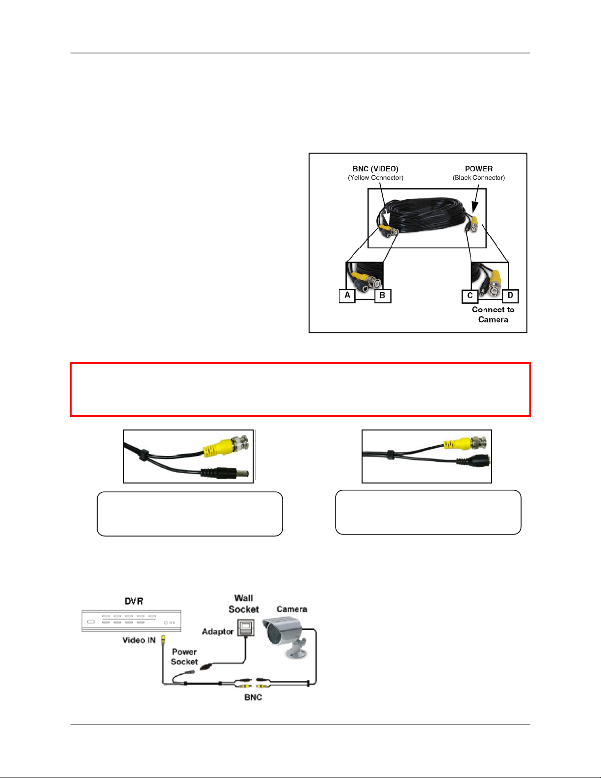
1. Connect the extension cable to the Camera and system:
A. Connect the Barrel Power connector to
a power adaptor.
B. Connect the BNC connector to an
available BNC Port on the DVR.
C. Connect the Male Power connector to
the Camera.
D. Connect the BNC connector to the
Camera.
2. Connect the Power Adaptor to a wall outlet.
ATTENTION: The ends of the extension cable are NOT the same - one end has a Male power port,
and the other has a Female power port. Before permanently running the Camera Extension Cable,
make sure that the cable has been oriented between the Camera and the unit correctly.
Male Power Port - The male power
port end of the Extension cable
connects to the Camera.
Connect to DVR and
Power Adaptor
Female Power Port - The female
power port end of the Extension cable
connects to the Power Adaptor.
Camera Connection Diagram
14
Page 15
y
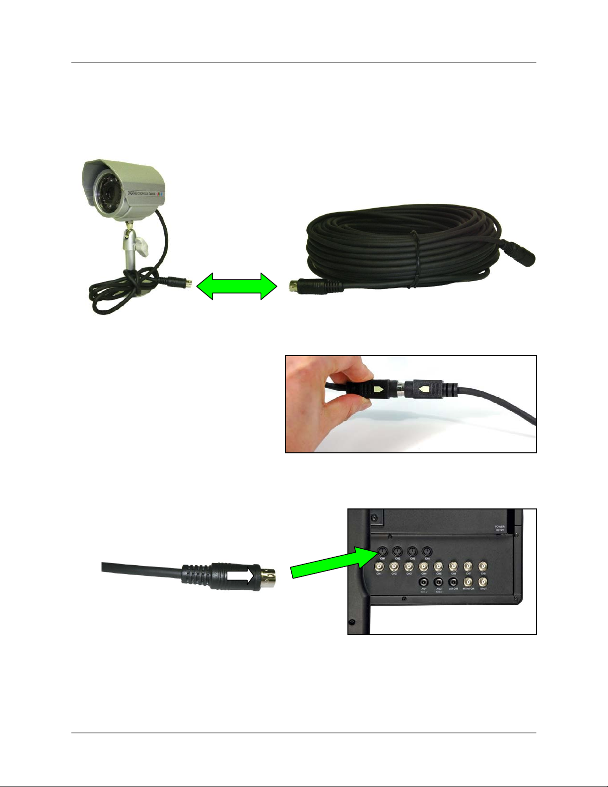
Connecting DIN Cameras*
1. Connect the female end of the extension cable (not included) to the camera.
*DIN cameras are not
included with this s
Note: Ensure that the arrows on the DIN
Camera Cable and the DIN Extension
Cable point together when connecting the
cable. If the pins in the DIN Cable are
bent, the camera will not function.
stem
L19WD Series
2. Connect the male end of the extension cable to an open DIN camera input on the rear panel
of the system.
Note: The arrow on the DIN camera should be facing up when connecting the DIN
Extension Cable to the system.
15
Page 16

Mouse Control
Mouse Control
This system has been designed to use a PS/2 mouse or remote control as its primary methods
of navigation and configuration. Connect the mouse to the PS/2 port located on the rear panel
before powering on the system. Once the unit has loaded, the mouse will be recognized by the
system.
Using the mouse
The mouse functions in the same manner as a PC mouse. Use the left and right buttons to open
menus and change options.
Left Button
Click:
• Select options and
change values in
menus, Recording
mode, and Search
mode
• Operate controls in
PTZ mode
Double-click:
• Double-click on a
channel in Quad or
split-screen view to
view the channel in
full-screen.
Right Button
Right-click:
• Switch between active
camera channels in fullscreen mode, or switch
between groups of channels
in Quad or split-screen views
• Motion Setup: Set motion
cells
• Digital Information Display
(DID): While running, rightclick in top-right corner of
screen to return to Live
Mode
Scroll-Wheel
• In PTZ Mode, Scroll Up
to Zoom In, Scroll Down
to Zoom Out.
16
• Changes values in
certain menus.
Page 17
L19WD Series
Function Bar
When using the mouse, the Function Bar is the primary on-screen tool for
accessing and changing system settings and configurations.
To open the Function Bar:
Mouse:
• Move the cursor over the bottom of the
screen.
RemoteControl:
• Press the FUNC button.
The Function Bar contains two main components:
1. Channel Display
2. Function Icons
1
2
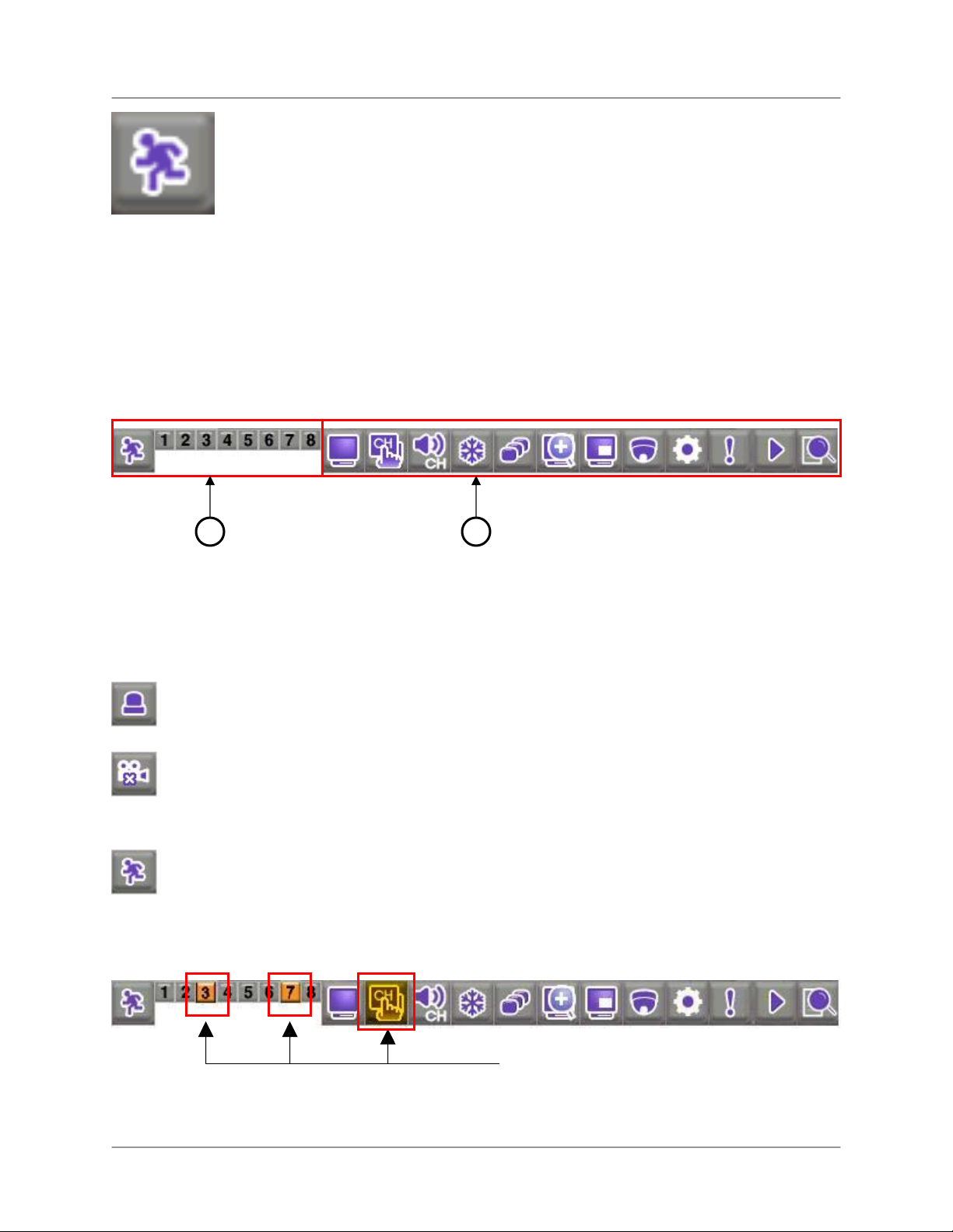
Channel Display
Click the icon to view the status of each camera in Alarm, Cam-Loss, or Motion.
Alarm – Panic recording. Panic Recording overrides all other recording modes of the
system.
Cam-Loss – The camera has become disconnected, or the signal has been lost.
Motion – Recording triggered by detection of motion.
Example of camera loss:
The Function Bar shows that cameras 3
and 7 have been disconnected.
17
Page 18
Mouse Control
Function Icons
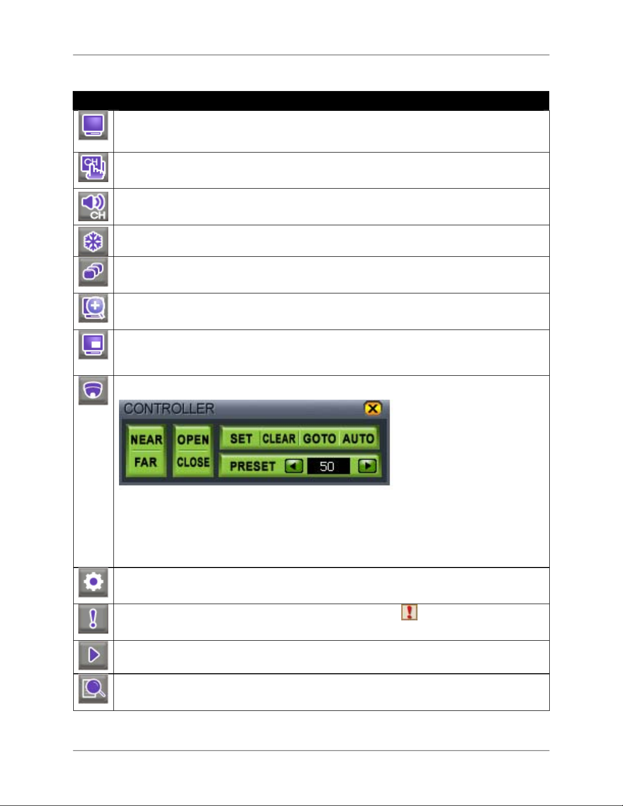
Icon Description
DISPLAY – Switches between Full-Screen, Quad, and split-screen views.
CHANNEL – Click to view any channel in Full-Screen mode.
AUDIO – Select an audio channel from 1~4; click OFF to turn off audio.
FREEZE – Freezes the image. Press ESC to cancel Freeze Mode.
SEQUENCE – Activates Sequence Mode for the connected cameras only. You can set the
display view (Full-Screen, Quad, 9-split) prior to activating Sequence Mode.
ZOOM – In Live mode, the image zooms in 2X in Full-Screen view. Click and drag the small
blue box in the bottom-right corner of the screen to view other areas of the image or use the
Navigation buttons on the Remote Control.
PIP – Activates the Picture-In-Picture (PIP) function.
One channel appears in Full-Screen, while another appears in a small inset window. The
small screen displays in sequence according to a preset interval.
PTZ – Opens the Pan, Tilt, Zoom (PTZ) Control Panel.
Note: PTZ cameras are not
included with this system.
See Appendix 10 for more
details.
18
o NEAR
o FAR
o OPEN
o CLOSE
o SET
Focus near
Focus far
Open iris
Close iris
Set preset
o GO TO
o AUTO
o PRESET
Go to preset
Auto scan
Enter present number
SETTINGS – Opens the System Control Panel (login: ADMIN; leave the password field blank).
See Using the System: Configuration for more details on changing your password.
PANIC – In case of emergency, click to start Panic Recording.
Appears on all channels;
system records in Continuous mode at highest video quality. Press again to cancel.
PLAYBACK – Click to playback recorded video. Pop-up control panel supports, play, pause,
forward/reverse, and next/previous.
SEARCH – Opens the Search menu; scan for recorded video by Date/Time, Event, or
Bookmark.
Page 19

Remote Control
Listed below is a quick reference for the Remote Control.
1. REC: Press REC to start Panic recording on the DVR.
MENU: Press to open the System Main Menu.
2. DVR 1-6 – Select DVR ID for controlling multiple
systems.
3. Numeric Keypad,
through individual channels in full-screen mode*; Press
to cycle through display modes: full-screen, quad,
,+
eight.
4. FUNC – Opens and closes the Function control bar.
SEARCH: Opens the search menu.
ESC: Exits menus, functions; stops playback.
AUDIO: Switch audio inputs (Ch. 1~4) or mute the
internal speaker.
MODE: Change screen displays: full-screen, Quad and
Split-Screen views.
5. ◄▲▼►, OK (Navigation Buttons) – Cycle through
menu options and change values. Operate PTZ
functions.
6. PTZ – Opens the PTZ menu.
7. Playback controls –
Jump to start of recording
o
o Slow motion speeds in Forward Playback: 1/4, 1/8,
1/16, and 1/32; Increase playback speed in
Reverse Playback: 2X, 4X, 16X, and 32X.
o
Reverse Playback
o Forward Playback
Pause
o
o Stop
o Increase playback speed in Forward Playback: 2X,
4X, 16X, and 32X; Slow motion speeds in Reverse
Playback: 1/4, 1/8, 1/16, and 1/32.
Jump to end of recording.
o
8. BACKUP – Opens the USB Backup menu.
9. SEQ, FRZ, PIP, ZOOM –
o SEQ Automatically cycle channels in sequence.
Select full-screen, Quad, or Eight-view prior to
pressing SEQ.
o FRZ In full-screen mode, freeze image; press Esc to
cancel. In Quad and Eight-view, activate freeze
features, then press corresponding numeric button
to freeze the image; press Esc to cancel.
o PIP Turn on picture-in-picture view.
o ZOOM Activate full-screen zoom mode. Use
navigation arrows to scan image; press ESC to
cancel.
– + – Press number buttons to cycle
L19WD Series
1
–
2
3
4
5
6
7
8
9
*L19WD1600 only: 0+0 = 10, 0+1 =
11, etc.
19
Page 20
Menu Navigation Control & Tips
Menu Navigation Control & Tips
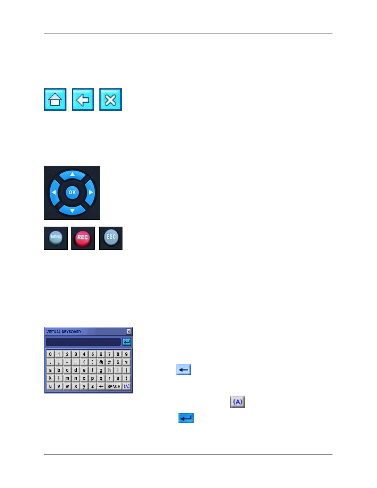
Using the Navigation Icons
Use the Navigation Icons when navigating the system menus.
• HOME Click the Home Icon while in any menu to return to the
System Main Menu.
• BACK Click the Back Icon to return to the previous menu.
• EXIT Click the Exit Icon to exit menus.
Using the Navigation Buttons
When using the remote control, the Navigation Buttons are
the primary way to move through the system menus.
• ◄► Press the Left and Right arrow buttons to choose different
options in menus.
• ▲▼ Press the Up and Down arrow buttons to change values
within options. These buttons can also choose different menu
options in certain menus.
• OK Press the OK button to change option values and confirm
selections.
• MENU Press the Menu button to open the System Main Menu;
you must first login with your user name and password.
• REC In an emergency, press the Record button to start Panic
Recording; press again to cancel.
• ESC Press the Escape button to close windows and menus.
Using the Virtual Keyboard
You need to use the Virtual Keyboard to change user
passwords and to edit camera names.
1. Click
title.
to delete the default password or camera
20
2. Enter a new password or camera title using the alpha-
numeric keypad. Press
3. Press
Keyboard.
to save changes and close the Virtual
to change case.
Page 21
L19WD Series
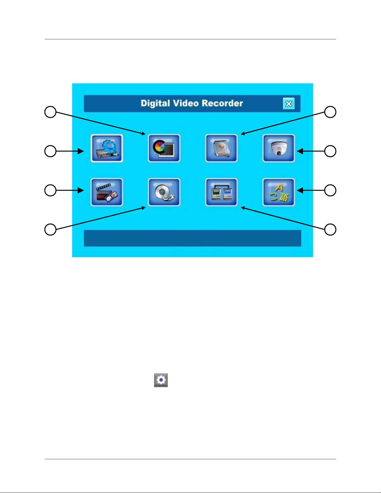
System Main Menu
2 3
1
5
6
1. CONFIGURATION
2. DISPLAY
3. HDD MANAGEMENT
4. CAMERA
4
7
8
5. RECORD
6. BACKUP/UPGRADE
7. NETWORK
8. LANGUAGE
To open the System Main Menu:
Mouse:
• From the Function Bar, click .
Remote Control:
• Press MENU.
Note: You must login to the system before you can access the System Main Menu.
21
Page 22
System Main Menu
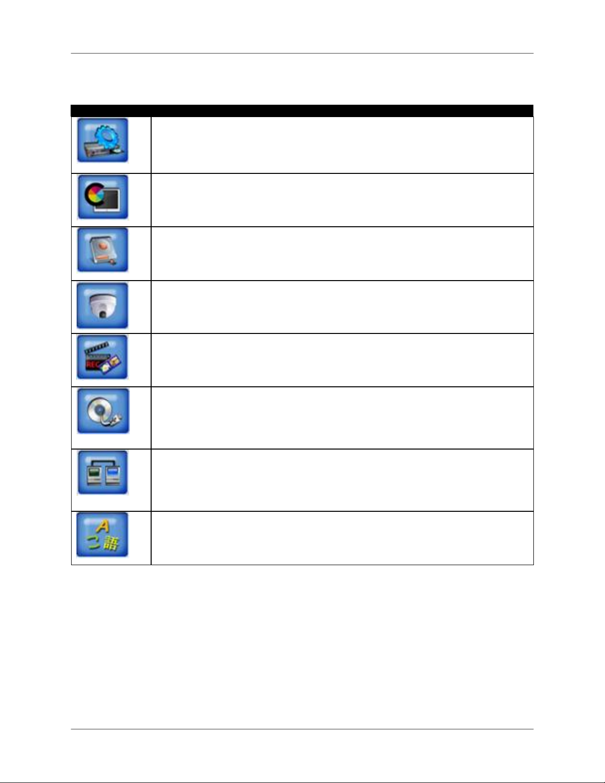
System Control Panel Icons
Icon Description
CONFIGURATION – Set Date/Time, Passwords, User Authority, Audio, System
Information, and restore factory defaults.
DISPLAY – Change display settings, adjust resolution, and enable DID Mode (Digital
Information Display).
HDD MANAGEMENT – Format hard disk and enable/disable disk overwrite.
CAMERA – Change Camera Title, adjust color, camera settings, alarm, motion, and
PTZ settings, and set Event pop-up.
RECORD – Configure Record Setup, Schedule, and Holiday settings.
BACKUP/UPGRADE – Backup data to USB storage device; upgrade firmware.
NETWORK – Adjust IP settings and connections, and enable/disable DDNS.
LANGUAGE – Change the system language to English, French, or Spanish.
22
Page 23
L19WD Series
Starting up the system
Once you have made all connections to the system and powered it on, you must login to the
system and set the date and time.
ATTENTION: When first logging in to the system, keep ADMIN as
your user name and leave the password field blank. See Using the
System: Configuration for more details on changing your password.
System login
To login to the system:
Mouse:
1. Move the cursor toward the bottom of the screen to open the Function Bar.
2. From the Function Bar, click .
3. Select your user name and password and click OK.
Remote Control:
1. Press the MENU button.
2. Use the Navigation Buttons and Numeric Keypad to select your username and password.
3. Select OK.
Note: You must login when accessing the following critical menus:
o Search
o PTZ
o HDD Clear
o Backup
23
Page 24
Starting up the system
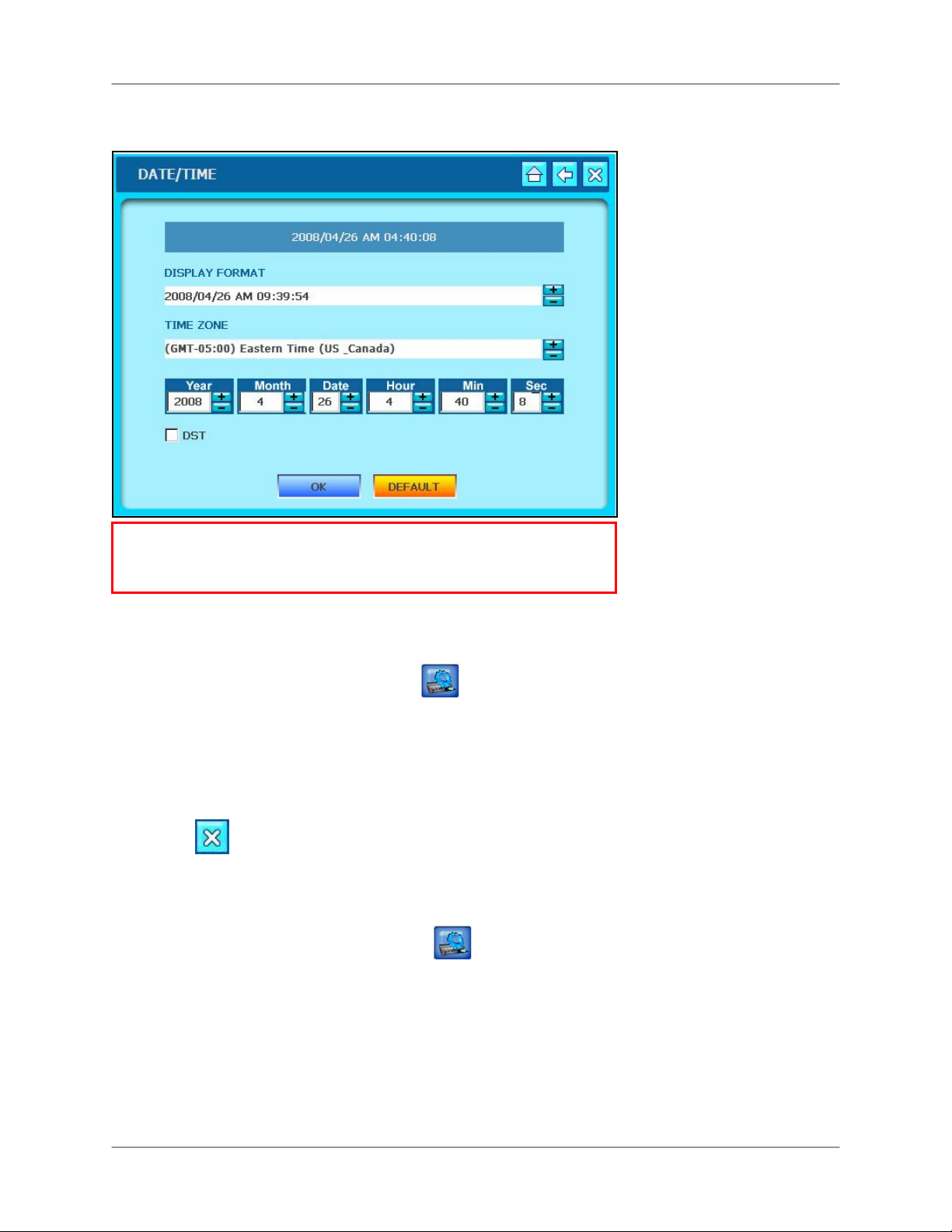
Setting the Date & Time
ATTENTION: You must set the date and time prior to setting a
recording schedule on the system. See Using the System: Record for
more details on setting a recording schedule.
To set the date and time:
Mouse:
1. From the System Main Menu, click
2. From the Configuration menu click DATE/TIME.
3. Click +/- to change the DISPLAY FORMAT, TIME ZONE and Date and Time for the
system. Check the DST box to enable Daylight Savings Time.
4. Click OK to save your settings or click DEFAULT to restore factory defaults.
5. Click
Remote control:
1. Press the MENU button and login to the system.
2. Using the Navigation Buttons, select
between menu options. Use
3. Select the DISPLAY FORMAT, TIME ZONE and Date and Time for the system.
4. Check the DST box to set Daylight Savings Time.
5. Select OK to save your settings or select DEFAULT to restore factory defaults.
to exit.
▲▼to change individual settings.
.
then select DATE/TIME. Use ◄►to cycle
6. Press the ESC button to exit.
24
Page 25
L19WD Series
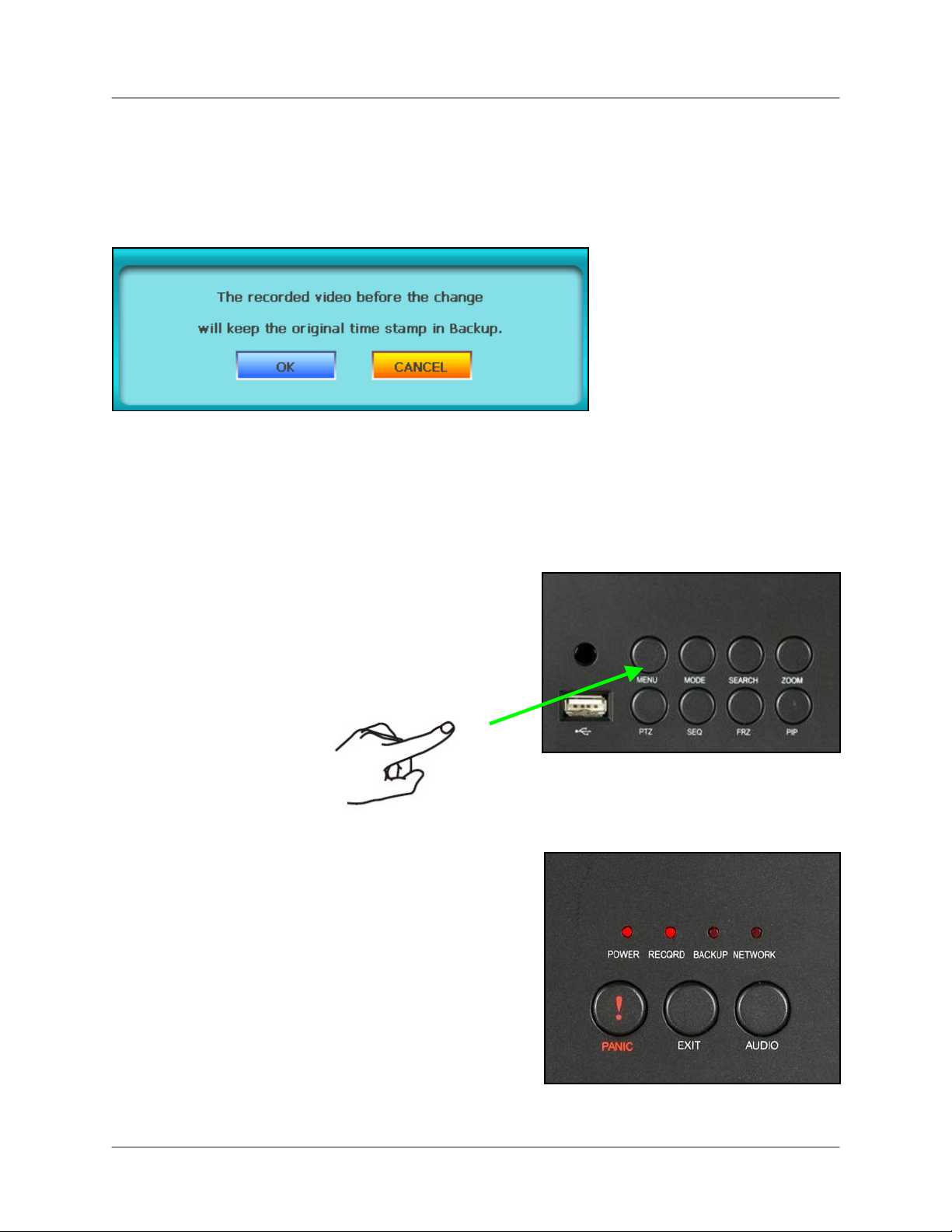
Time Stamp
When you change the date and time after recording video data. A pop-up window appears
informing you that the recorded video before the time change will keep the original time stamp.
The same applies for changes to Daylight Savings Time (DST).
Turning the monitor off
• From the front panel, press and hold the MENU button
for 3 seconds.
• The system continues to record while the monitor is shut
off. LED lights remain lit on the front panel. This useful to
disguise the fact that the system is a security monitor.
• Press the MENU button again to turn the monitor back on.
Note: Only pressing the MENU button will turn the
monitor back on.
25
Page 26
Starting up the system
Turning the monitor off (cont’d.)
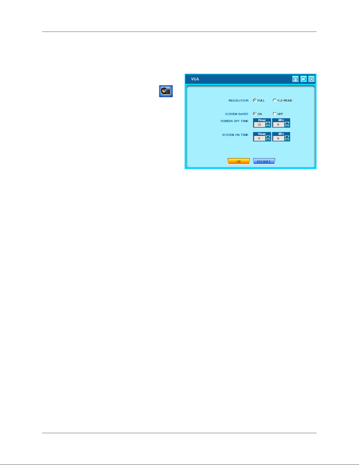
The monitor can also be set into Screen Saver mode:
1. From the System Control Panel click
and then click VGA.
2. Click Screen Saver ON.
3. Enter the SCREEN OFF time and SCREEN
ON time. The system uses the 24-hour
clock.
4. Click OK to save your settings or click
DEFAULT to restore factory defaults.
26
Page 27
Display Modes
The system features the following modes:
L19WD Series
• Live Mode
• Full-Screen, Quad, &
Split-Screen views
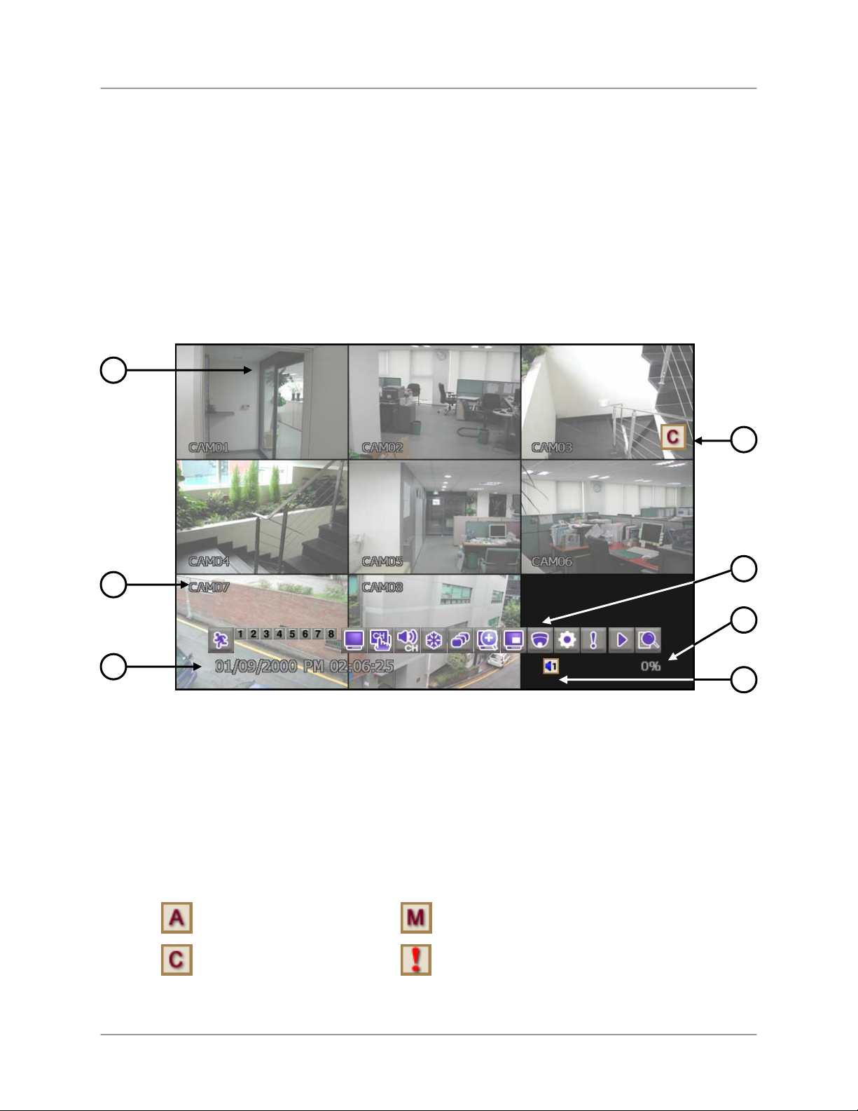
Live Mode
1
2
• Playback Mode
• Search Mode
4
5
3
1. Live – Displays the Live view of each camera. Available in Full-Screen, Quad, and Split-
Screen views.
2. Camera Title – Displays the name of each camera by channel. You can change the name
of each camera channel in the Camera menu of the System Control Panel.
3. Date/Time – Shows the date/time, network status, active audio channel and used hard disk
space.
4. Recording Mode – The system uses the following icons to indicate its recording status:
• Alarm
•
Continuous
• Motion
• Panic
6
7
27
Page 28
Display Modes
5. Function Bar – Fast. mouse-driven access to the many functions of the System.
6. Audio – Shows the active audio channels or the mute internal speaker.
7. Hard drive space – Shows the percentage of used hard drive space.
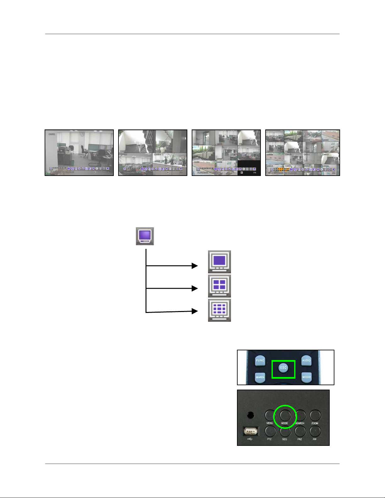
Full-Screen, Quad, & Split Views
The L19WD Series has several display views available: Full-Screen, Quad-View, and SplitScreen Views. You can easily change the display view through the system’s three input
methods: mouse, remote control, and front panel.
Full-Screen View Quad View 8-Split View 16-Split View*
To change display views:
Mouse:
• From the function bar, click :
Remote Control:
• Press the MODE button to cycle through the display modes.
Front Panel:
• Press the MODE button to cycle through the display modes.
*16-split screen view only available on L19WD1600.
Full-Screen
Quad-View
Split-Screen View*
28
Page 29
:
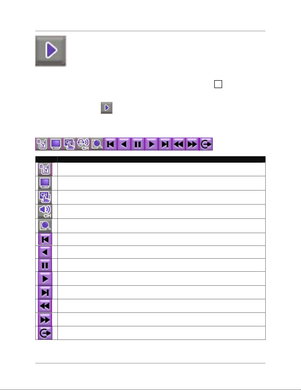
Playback
View recorded video on the system through Playback mode.
Playback Bar Icons
To open Playback mode:
Mouse:
1. While in Live Mode, move the
2. Click
cursor over the bottom of the
screen.
and login with your
username and password.
L19WD Series
Remote Control
1. Press the
► button.
2. Enter your username and
password and select OK.
Icon Description
BOOKMARK – Click to bookmark a point in playback for future reference.
DISPLAY – Switch between Full-Screen, Quad, and Split views.
DISPLAY CHANNEL – Select to view any channel in Full-Screen mode.
AUDIO CHANNEL – Select audio channels 1 or 2*; click OFF to turn off audio.
SEARCH – Open the Search Menu to view playback recorded video.
BACK – Move to the start of all recorded video.
REVERSE PLAYBACK – View playback in reverse.
PAUSE – Pause playback.
PLAY – Start playback.
END – Move playback to the end and stop.
SLOW MOTION PLAY – Slow motion speeds in Forward Playback: 1/4, 1/8, 1/16, and 1/32;
Increase playback speed in Reverse Playback: 2X, 4X, 16X, and 32X.
FAST FORWARD – Increase playback speed in Forward Playback: 2X, 4X, 16X, and 32X;
Slow motion speeds in Forward Playback: 1/4, 1/8, 1/16, and 1/32.
EXIT – Quit Playback Mode.
*Audio configuration varies by model.
29
Page 30
Display Modes
R
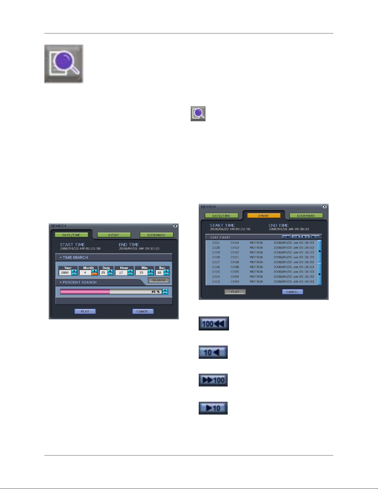
Search Mode
Search the system for recorded video by date / time, event, and
bookmarks.
DATE/TIME
Search for recorded video data according
to date and time.
Note: START TIME and END TIME in the
DATE/TIME menu shows the start and end
of recording. They cannot be edited.
To open the Search Menu:
Mouse:
1. From the Function Bar, click
2. Enter your username and password
and click OK.
emote Control:
1. Press the SEARCH button.
.
2. Use the navigation buttons to
enter your username and
password and select OK.
EVENT
Search for recorded video data according
to Events. Events include Motion, Alarms,
and Video Loss from any of the cameras.
• TIME SEARCH– Click +/- to enter the Date
and Time and click Search.
• PERCENT SEARCH– Click +/- or click
anywhere in the progress bar to search a
certain portion of the recording time.
30
• Click ▲▼ to scroll through the event list.
Click to view the previous hundred events.
Click to view the previous ten events.
Click to view the next hundred events.
Click to view the next ten events.
Page 31
L19WD Series
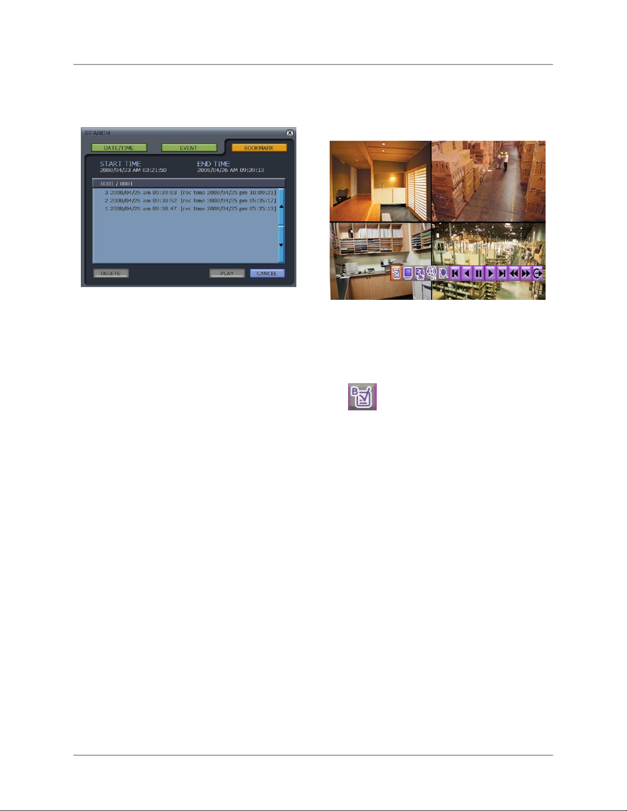
BOOKMARK
Search for recorded video data according
to Bookmarks.
To search video data by bookmark:
1. Open the Search menu and click
BOOKMARK.
2. Click one of the bookmarks from the list
and click PLAY. If you have many
bookmarks, click
▲▼ to scroll
through the bookmark list.
Setting Bookmarks
You can set bookmarks in recorded video
data to mark unique moments of activity or
interest for future reference.
To set bookmarks:
1. Search for recorded video by either
DATE/TIME or EVENT. The Playback
Control Bar appears during playback.
2. From the Playback Control Bar, click
. A dialogue window informs you
to wait and then playback resumes.
Note: The system can save a maximum of
1000 bookmarks.
To delete bookmarks:
1. Open the Search menu and click
BOOKMARK.
2. Select a bookmark and then click
DELETE.
Note: You can only delete one bookmark
at a time.
31
Page 32

Using the System
Using the System
You can now begin to explore the main menu of your system.
Configuration
Open the Configuration menu from the System
Control Panel to adjust various system settings.
BUZZER
Check the boxes to turn system beep,
alarms, and buzzer sounds on/off.
• KEY BEEP – Beeps when you click the
mouse or press buttons on the remote
control.
• VIDEO LOSS – Alarm sound when video
signal is lost from a camera.
• ALARM IN – Alarm sound for connected
external security alarm.
• MOTION DETECT – Alarm sound whenever
motion is detected.
Click OK to save your settings, or click
DEFAULT to restore factory defaults.
PASSWORD SETUP
Set password for the various users of the
System. The system has a total of ten
users:
o 1 Administrator (Admin)
o 3 Managers
o 6 Users
To change your password:
1. Click
2. Using the Virtual Keyboard, enter the
3. Enter a new password.
4. Re-enter the new password to
◄► to select the USER. The
Virtual Keyboard opens.
current password for that user.
confirm and click OK.
32
See Using the Virtual Keyboard for more
details on using the Virtual Keyboard.
Note: The password has a maximum
length of ten digits.
Page 33

USER AUTHORITY
If many people will be operating the
system, you can set restrictions for which
system settings users can access.
Check the boxes to limit access to system
settings for different users.
Note: By default, ADMIN has access to all system
settings.
• CONFIGURATION– Change various
system settings including date & time and
passwords.
L19WD Series
• LANGUAGE – Change the system
language to English, Spanish, or French.
• SEARCH – Search the system for recorded
data. Search by date & time, events, and
bookmarks.
• PTZ – Change settings for PTZ cameras
(not included).
Click OK to save your settings, or click
DEAULT to restore factory defaults.
• DISPLAY – Change graphic displays on the
main System Screen and Playback Screen.
• HDD MANAGEMENT – Format the hard
disk and set disk Overwrite On/Off.
• CAMERA – Rename camera channels,
adjust color and brightness, and adjust
settings for motion sensitivity.
• RECORD – Adjust record settings, along
with recording schedule.
• BACKUP/UPGRADE– Backup data to an
external device via USB or update the
system’s firmware.
• NETWORK – Change network IP settings,
Web Server, and enable DDNS for remote
viewing of the system.
33
Page 34

Using the System
RS-232C
REMOTE CONTROL
Adjust settings for an external
communication device.
• BAUDRATE– Transmission speed between
the system and the device.
• LENGTH – The length of the transmission
signal.
• STOP BIT– Bit that indicates that a piece of
information has just been transmitted.
• PARITY – Can help detect errors in
transmission.
• FLOW CONTROL– Assign control of signal
transmission to hardware or software.
Click OK to save your settings, or click
DEFAULT to restore factory defaults.
Set the remote control up to six units of the
L19WD series.
To assign remote control functionality:
1. From the Remote Control drop-down
menu, select ALL to control up to six
systems simultaneously.
OR
1. Select 1-6 to assign a specific
L19WD series unit to the remote
control.
2. Press the corresponding button on
the remote control (DVR1 – DVR6) to
control only that specific system.
Click OK to save your settings, or click
DEFAULT to restore factory defaults.
34
Note: If you select 01 in the Remote Control
settings, you must press DVR1 on the remote
control to operate the system.
Page 35

L19WD Series
AUDIO*
Set volume levels for the two audio inputs of
the system.
To change audio settings:
Mouse:
1. Click and drag the bar left/right to
adjust the volume.
2. Click the radio button to assign audio
recording to one of the four 6-pin DIN
cameras. DIN cameras can only be
connected in channels 1~4.†
Remote Control:
1. Press
channel, then press
◄►to select and audio
▲▼to adjust
the volume.
2. Press
◄►to select the buttons, then
press OK to check.
Click OK to save your settings, or click
DEFAULT to restore factory defaults.
ATTENTION: You can only record two
channels of audio on the system**: one
audio-capable BNC camera or one DIN
camera records audio for channels 1~4; one
audio-capable BNC camera records audio for
channels 5~8. You cannot have a DIN
camera and an audio-capable BNC camera
recording audio at the same time on
channels 1~4.
*Audio capable cameras may not be included with
your system.
**Four audio channels on the L19WD1600.
† Audio control for DIN cameras only available on
L19WD800.
SYSTEM INFORMATION
View important system information:
• IP Address – The IP address of the system
when on a network.
• MAC Address – MAC address of the
system. Necessary for networking or setting
up remote viewing.
• Disk Capacity – Displays the total size of
the system hard disk and amount presently
in use.
• F/W Version – Firmware version.
• Video Signal Type – Video format of the
system: either NTSC in North America or
PAL in Europe.
• DDNS Domain Name – Domain name used
with the Lorex Client Software to let you
view your system remotely over the Internet
from another PC.
• Net Client Port – The port that allows your
system to communicate to other PCs or
devices over a network. By default, the Net
Client port is 5000.
• Web Server Port – The Web Server port
(by default, 80) to let external PCs or
devices communicate with your system over
the Internet.
35
Page 36

Using the System
FACTORY DEFAULT
Reset factory defaults on System, Channel
Data, PTZ, Network, or Record data.
Note: Resetting factory defaults will not
erase recorded data from your hard disk.
To reset factory defaults:
• Check the box, SELECT ALL, to reset all
settings
OR
• Check the individual boxes for SYSTEM,
CHANNEL, PTZ, NETWORK, and
RECORD settings.
Click OK to save your settings, or click
DEFAULT to restore factory defaults.
Note: Network is excluded from
SELECT ALL. To reset your network
settings to factory defaults, check the
Network box individually.
36
Page 37

play (
L19WD Series
Display
Open the Display menu from the System Control Panel to set graphical
displays during Live view and Playback, and edit settings for the Digital
Information Dis
DID).
DISPLAY SETUP
Check the boxes to turn graphical displays in
Live mode and Playback on/off.
• DATE/TIME – Shows the date and time in
the lower left corner.
• CHANNEL STATUS– The active status for
each of the cameras: Continuous, Motion,
Alarm, or Panic.
• TOTAL STATUS– Show the percentage of
the hard drive currently in use. Also shows
the active Audio Channel.
• CAMERA TITLE– Display the name of the
camera channels.
Click OK to save your settings, or click
DEFAULT to restore factory defaults.
INTERVAL
Set the time intervals for Sequence Mode
(SEQ), Picture-In-Picture (PIP), and Spot
Monitor. You can also set the timeout for
the on-screen menu. A short timeout
means any on-screen menus will
disappear quickly without user input; a
longer timeout means menus will remain
on-screen longer.
To change time intervals:
Mouse:
1. Click the arrows to adjust the time
interval (in seconds) for SEQ, PIP, and
Spot Monitor.
2. Click the drop-down menu to adjust the
timeout of the on-screen menu.
Remote Control:
1. Press ◄►to select between SEQ, PIP,
and Spot Monitor, then press ▲▼to
change the time increment.
2. Press ◄►to select the drop-down
menu, and then press OK to select a
time interval for the menu timeout.
Click OK to save your settings, or click
DEFAULT to restore factory defaults.
37
Page 38

Using the System
VGA
Set the system’s screen resolution and adjust
the settings for the Screen Saver (monitor
automatically turns on/off).
• RESOLUTION – Change the screen ratio to
16:9 widescreen or 4:3 full-screen.
• SCREEN SAVER – Turn the Screen Saver
On/Off.
• SCREEN OFF – Set the time (in 24 HR
clock) that the system will automatically turn
off the monitor.
• SCREEN ON – Set the time (in 24 HR
clock) that the system will automatically turn
on the monitor.
Click OK to save your settings, or click
DEFAULT to restore factory settings.
Note: When the monitor is turned off,
press and hold the MENU button on
the front panel to turn the monitor on.
Only the MENU button can turn the
monitor back on.
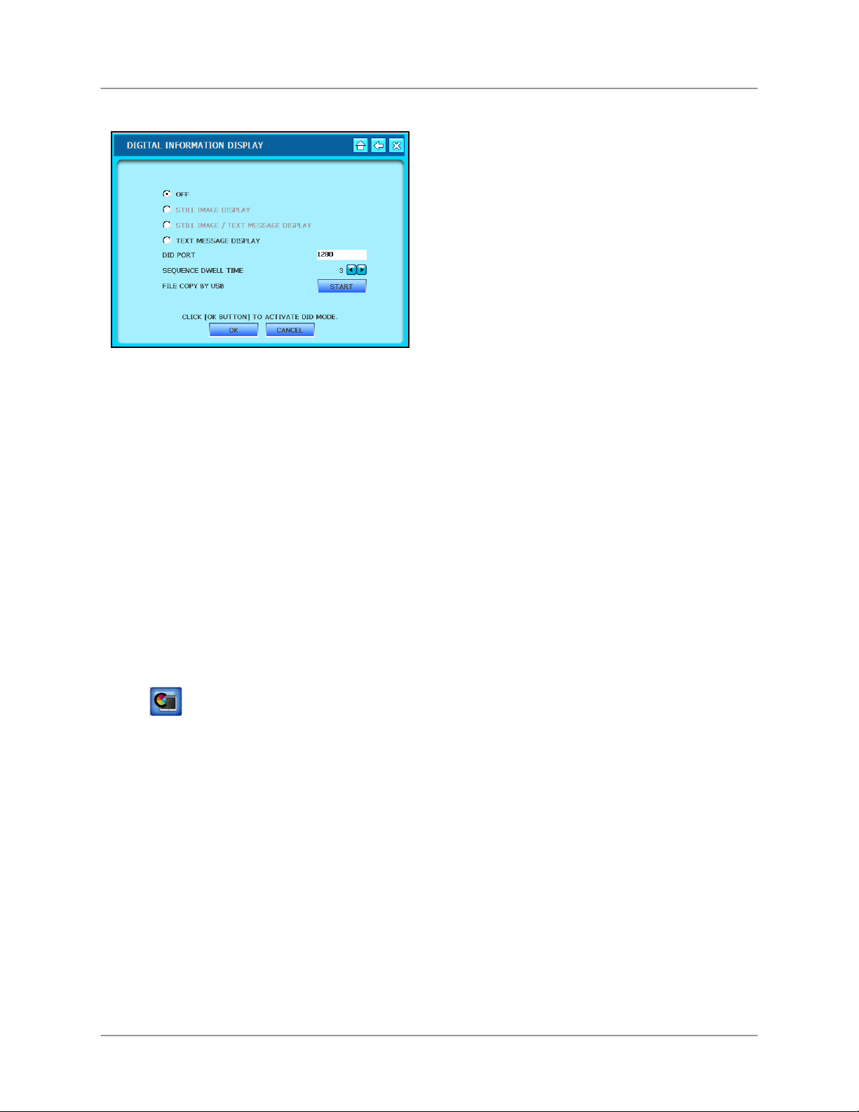
DIGITAL INFORMATION DISPLAY (DID)
Use Lorex Message Master (included on the
Software CD) to send text and digital images
(JPEG) to the system. Use the text and still
images for announcements, advertising, or
other retail purposes.
• STILL IMAGE DISPLAY – Display a slide
show of still images (JPEG)
• STILL IMAGE/TEXT MESSAGE DISPLAY
– Display both a still image slide show and
text
• TEXT MESSAGE DISPLAY – Display still
or moving text at the bottom of the screen.
• DID PORT – By default, 1280 is the fixed
port for the system to communicate with
Lorex Message Master. You set the port to
whichever port you want using the Virtual
Keyboard.
• SEQUENCE DWELL TIME – Set the length
of time (in seconds) that the digital images
remain on screen.
• FILE COPY BY USB – Transfer image files
to the DID via the USB port.
38
Note: Maximum file size is 2.0 MB. If
files are larger than 2.0 MB, they may
not transfer properly to the System.
Page 39
DIGITAL INFORMATION DISPLAY (cont’d)
L19WD Series
DIGITAL INFORMATION DISPLAY (cont’d)
Recommended image resolution for JPEG
files:
To enable the DID:
1. Click the radio buttons for STILL
IMAGE, TEXT MESSAGE DISPLAY
or STILL IMAGE/TEXTMESSAGE
DISPLAY.
2. Click OK. The slide show starts.
3. To exit the slide show, use the
mouse and right-click in the top-right
corner of the screen.
4. Login with your username and
password to return Live Mode.
NTSC
>
720x480 / 1440x960
PAL
720x576 / 1440x1152
If you transfer a JPEG file that does not
conform to the recommended image
resolution, it may not fit in the full screen.
To copy files by USB:
1. Insert a USB flash drive into the front
panel of the system.
2. From the System Main Menu, click
and then click DIGITAL
INFORMATION DISPLAY.
3. Under File Copy by USB, click
START. Click OK in the next window.
From the DID menu, click OK to save your
settings, or click CANCEL to exit without
saving.
39
Page 40

Using the System
HDD Management
Format the hard disk, view HDD info, and set disk
Overwrite on and off.
HDD SETUP
Use Clear HDD to format the hard disk.
This erases all recorded video data from
the hard disk. By default, the system
comes with a pre-formatted hard disk.
ATTENTION: Only format the hard disk if
absolutely necessary. All the data on your
hard drive will be lost. You cannot undo
this step
OVERWRITE
Overwrite determines how data is
maintained when the hard disk is full.
With Overwrite turned on, data is
overwritten once the hard disk is full,
starting with the oldest recording.
If Overwrite is turned off, the system stops
recording once the hard disk is full;
recording stops and the Buzzer activates.
The Overwrite Icon appears in place of the
hard drive percentage icon.
Note: Use the hard drive percentage
icon in the bottom-right corner of the
screen to keep track of the space
remaining on your system’s hard disk.
HDD INFO
Click HDD Info to see the Model Number,
Serial Number, and Size of your system’s
hard disk.
To format the hard disk:
1. Click START.
Login screen pops-up.
2. Enter your username and password
and click OK.
Screen icons turn grey as system
clears the hard disk.
3. Click OK.
Note: Clearing the hard disk will not
delete your system settings.
40
Page 41
L19WD Series
Camera
Rename camera channels, adjust color, set motion
sensitivity, and configure PTZ cameras (not included).
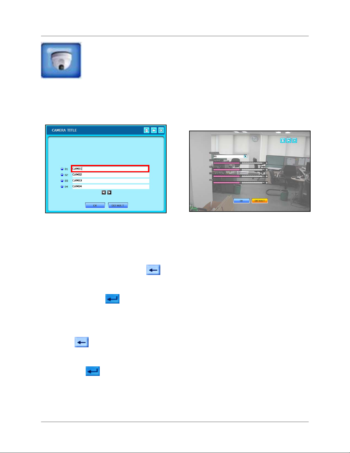
CAMERA TITLE
Use the Virtual Keyboard to rename
individual camera channels.
To change the camera title:
Mouse:
1. Click the text field to select one of the
cameras. Click
◄►to switch between
groups of cameras.
2. From the Virtual Keyboard, click
to erase the default camera name.
COLOR ADJUSTMENT
Use the sliders to adjust Brightness, Contrast,
Saturation, and Hue for each camera.
To adjust camera color:
Mouse:
1. Click the drop-down menu to select the
camera.
2. Click and the hold the slider bar to
increase and decrease BRIGHTNESS,
CONTRAST, SATURATION, and HUE.
The active slider bar turns green.
3. Enter a new name for the camera
channel and click
.
Remote Control:
1. Press ◄► to switch between Cameras
and press OK to select.
2. Select to delete the default
camera name.
3. Enter a new for the camera channel
and select
.
Click OK to save your settings, or click
DEFAULT to restore factory defaults.
Remote Control:
1. Press ◄► to select the drop-down
menu and press ▲▼ to select a
camera.
2. Press ◄► to select a slider bar and
press ▲▼ to increase or decrease.
The active slider bar turns green.
Click OK to save your settings, or click
DEFAULT to restore factory defaults.
41
Page 42
Using the System
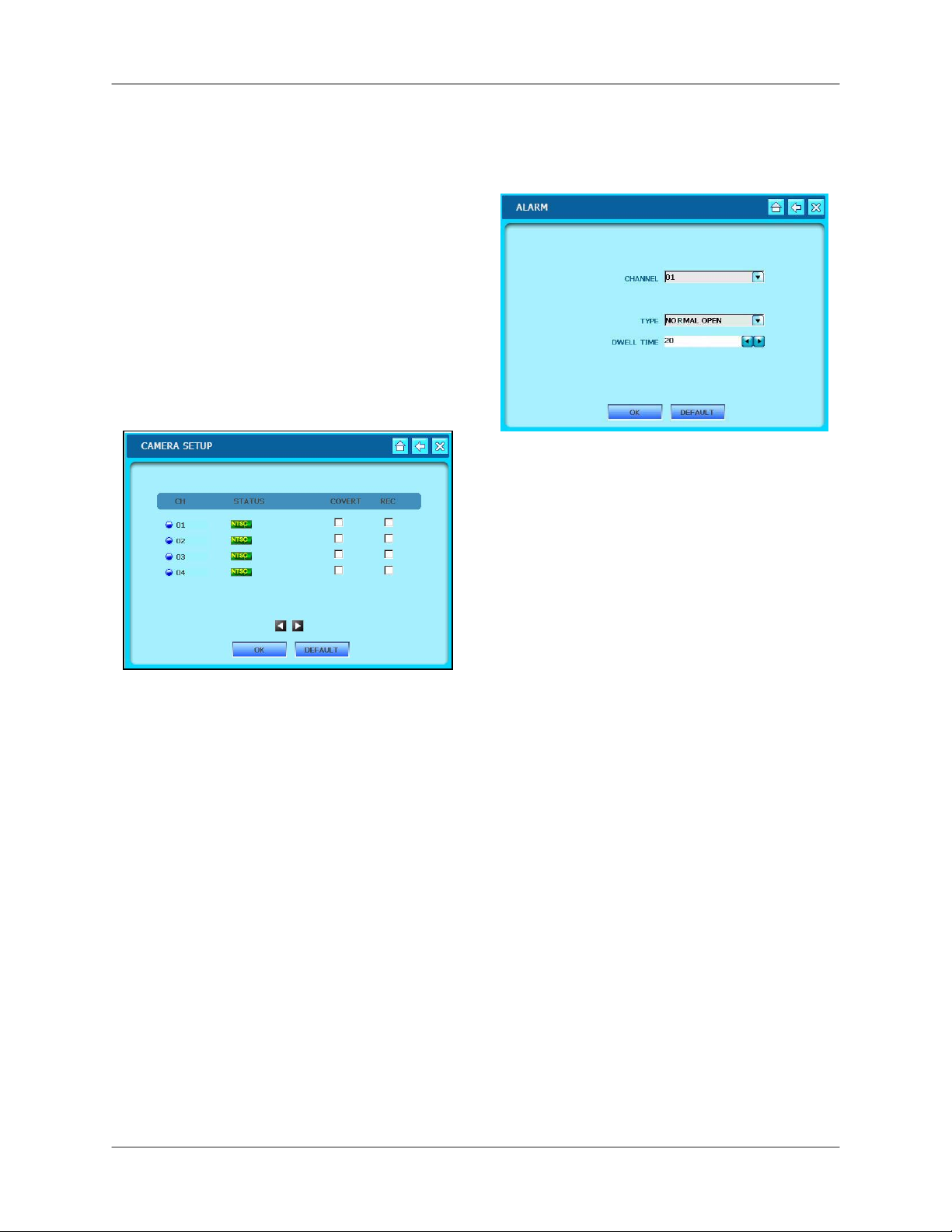
CAMERA SETUP
View the type of cameras (NTSC/PAL) or if
there is no camera connected (icon of a
grey camera).
Disable Record if you want to use a
camera only for observation.
Covert turns the onscreen display of the
camera ON/OFF. Covert cameras continue
to record, though the image is not
displayed onscreen. Use this feature if the
Monitor is located in a public area and a
camera should not be displayed (e.g. a
camera in a cash-count room or above a
cash register).
ALARM
Configure settings for an external Alarm
Sensor.
To configure Alarm settings:
Mouse:
1. Click the Channel drop-down menu to
select a channel to display the Alarm
notification.
To set Covert and Record:
Mouse:
1. Check the boxes in the Covert or
Record columns to enable these
functions on cameras 1-4.
2. Click ◄► at the bottom of the
window to cycle between groups of
cameras.
Remote Control:
1. Press ◄► to select boxes in the
Covert and Record columns.
2. Press OK to check the box.
3. Press ◄► to select the arrows at
the bottom of the screen and press
OK to cycle between groups of
cameras.
2. Click the Type drop-down menu to
select either NORMAL OPEN,
NORMAL CLOSED, or OFF.
3. Click ◄► to set the DWELL TIME (in
seconds) for the alarm notification. The
higher the dwell time, the longer the
alarm notification remains on the
selected alarm channel.
Remote Control:
1. Press ◄► to select the CHANNEL
drop-down menu and press ▲▼ to
select a specific channel for alarm
notification.
2. Press ◄► to select the Type dropdown menu and press ▲▼ to select
either NORMAL-OPEN, NORMAL-
CLOSED, or OFF.
3. Press ◄► to select the DWELL TIME
text field and press ▲▼ to increase or
decrease the Dwell Time.
Click OK to save your settings, or click
DEFAULT to restore factory defaults.
Click OK to save your settings, or click
DEFAULT to restore factory defaults.
42
Page 43
L19WD Series
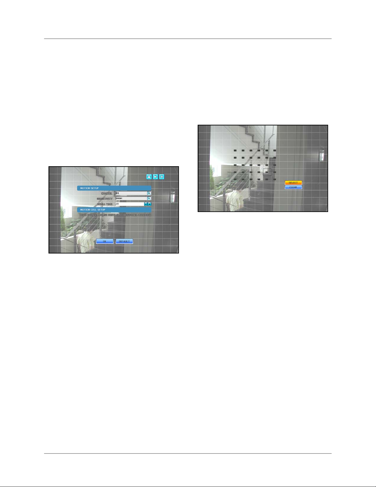
MOTION
Set the Motion Sensitivity for each camera
channel.
Use Motion Cell Setup to apply motion
detection to only a certain area of the
image. For example, if you want to closely
monitor a door, you can apply motion
sensing to only the area of the door, not
the whole image.
Note: In the Motion Menu, all images from
connected cameras will turn green as they
detect movement. Use this feature to help
you with Motion Cell Setup.
select Low, Medium, High, or Very
High.
3. Press ◄► to select the DWELL TIME
text field and press ▲▼ to increase or
decrease the Dwell Time.
Click OK to save your settings, or click
DEFAULT to restore factory defaults.
To configure Motion Cell Setup:
To configure Motion Setup:
Mouse:
1. Click the CHANNEL drop-down menu
to select the channel you want to
configure.
2. Click the Sensitivity drop-down menu to
select either Low, Medium, High, or
Very High.
3. Click the DWELL TIME arrows to
increase or decrease the DWELL
TIME. The higher the Dwell Time, the
longer the channel with motion
detection remains in Full-Screen view.
Remote Control:
1. Press ◄► to select the Channel dropdown menu and press ▲▼ to select an
individual channel.
2. Press ◄► to select the Sensitivity
drop-down menu and press ▲▼ to
Mouse:
1. Right-click on the screen to open
Motion Cell grid.
2. Click and drag across the screen to set
a specific motion sensitive area.
3. Click SELECT to enable the motion
sensitivity to the selected cells. Cells
are clear.
4. Click CLEAR to disable the area of
motion sensitivity. Cells turn solid grey.
Click OK to save your settings, or click
DEFAULT to restore factory defaults.
Note: By default, motion detection is
enabled on the entire image of each
connected camera
is active, move your hand in front of the
camera – the active cells turn green.
. To verify that motion
See Appendix 5 for more details.
43
Page 44

Using the System
PTZ
Configure settings for PTZ cameras (not
included).
• CHANNEL – The channel for the connect
PTZ camera
• PROTOCOL – The model of PTZ camera
• ID – Identification value for the PTZ camera
• BAUDRATE – Set the transmission rate for
the PTZ camera
• PAN – Horizontal movement speed
• TILT – Vertical movement speed
• ZOOM – Zoom In/Out speed
• FOCUS – Focus Near/Far speed
Click OK to save your settings, or click
DEFAULT to restore factory defaults.
EVENT POPUP
Set notifications for motion or alarm
events.
• CHANNEL – Select the channel for the
Event popup
• POPUP – Turn popup On/Off
• EVENT – Select either Motion or Alarm
events
• DWELL TIME– Set the Dwell Time for the
event popup. The higher the dwell time, the
longer the Event popup remains in fullscreen view
Click OK to save your settings, or click
DEFAULT to restore factory defaults.
44
Page 45

L19WD Series
Record
Configure Record settings and set recording and
holiday schedules.
RECORD SETUP
Configure Record settings, including image
quality, frames-per-second, and pre-alarm
recording.
Use the drop-down menus to change the
following settings:
• CHANNEL – Select the group of channels
to apply settings.
• QUALITY – Set the quality of recording:
Normal, High, Highest.
• FPS – Set the Frames Per Second for the
group of channels from 3, 5, 10, 15, and 30
fps (real-time video capture).
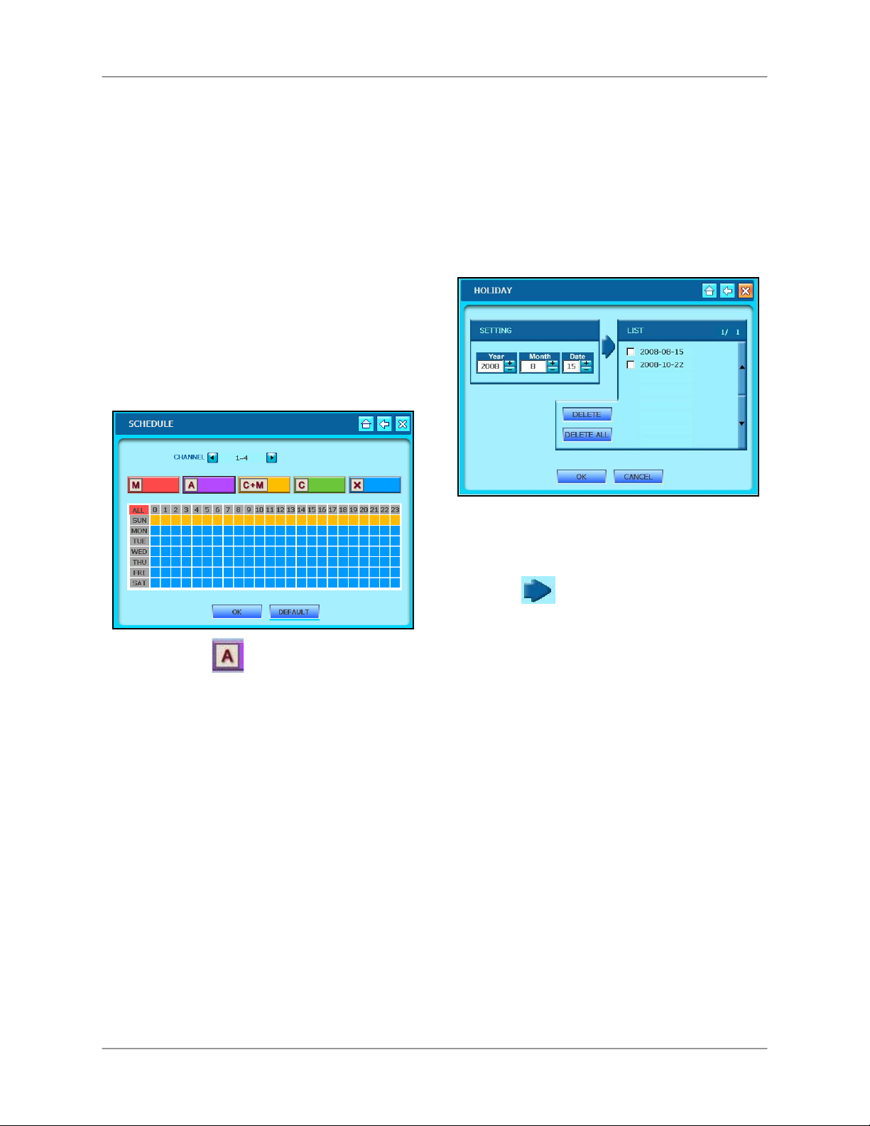
SCHEDULE
Set scheduled recording cameras for
groups of cameras. Apply any of the five
recording modes by day and hour.
Motion – System only records if
motion is detected in the selected time
interval.
Alarm – System records only when
an alarm is triggered.
• PRE ALARM– When an alarm is detected,
the Pre Alarm begins recording from before
the alarm was detected (retrieved from
video cache). Set the Pre Alarm time from
1-5 seconds, or turn it Off.
Note: The Record Setup window displays
the record time remaining based on your
selected settings and hard drive capacity.
Click OK to save your settings, or click
DEFAULT to restore factory defaults.
C+M – System records
continuously and still keeps a log of motion
events.
Continuous – System constantly
records from the camera.
No Recording – System does not
record any video data based on blocked
intervals in the schedule.
ALL – First click a recording mode, then
click ALL to apply the selected recording
mode to the entire schedule.
45
Page 46
Using the System
Schedule (cont’d)
To set a recording schedule:
Mouse:
1. Click the ◄► to select a group of
channels (number varies depending on
your system).
2. Click one of the five recording modes
(M, A, C+M, C, X).
3. Click one of the tiles in the table
according to the day and hour(s) you
want to apply the record mode. For
example, if you wanted Alarm
recording from midnight to 6 AM,
Monday-Friday:
Holiday
Set the system to record when you are
away on holiday or for national holidays.
Note: Holiday records according to the
Sunday recording schedule. Whatever
recording mode(s) you have scheduled for
Sunday will be used for dates in your
Holiday list. See PREVIOUS SECTION.
To set Holiday Recording:
i. Click .
ii. Click and drag across the table
from tile “MON-0” to tile “FRI-5.”
The selected area turns purple to
indicate Alarm recording is
enabled from 12 AM to 6 AM,
Monday-Friday.
4. Repeat steps i-ii for whichever
recording mode you want to schedule.
5. Click OK to save your settings or click
DEFAULT to restore factory defaults.
Note: Sunday schedule is used for Holiday
record setting. See NEXT SECTION.
5. Under SETTING, enter the date you
want to include in the Holiday list.
6. Click
to add the date to the list.
7. Click OK to save your settings or
CANCEL to quit without saving.
To delete dates from Holiday Recording:
1. Under LIST, check the box beside the
specific date you want to delete.
2. Click DELETE.
OR
1. Click DELETE ALL without checking
any boxes to delete all dates from the
Holiday Recording list.
2. Click OK to save your settings or click
CANCEL to quit without saving.
46
Page 47

L19WD Series
Backup / Upgrade
Upgrade system firmware and backup data to a USB flash drive.
UPGRADE
New firmware is periodically available for
download from the Lorex website
(www.lorexcctv.com
). You can update the
firmware on the unit via the USB port on
the front panel.
To upgrade the system’s firmware:
1. Download the latest firmware for your
system from www.lorexcctv.com
to
your PC and copy the file to a USB
flash drive.
2. Insert the USB flash drive into the front
panel of the system.
3. From the System Control Panel click
USB BACKUP
Archive recorded data from the system by
connecting an external USB flash drive.
Note: Make sure you have deleted all data from
the USB drive. The system will format the USB
drive, erasing all data, in preparation for the
archive process.
To backup data via USB:
1. Connect an external USB flash drive to
the front panel of the system.
2. From the System Control Panel, click
and click USB BACKUP. You
must enter your username and
password.
and click UPGRADE.
4. Click FIRMWARE UPGRADE for the
system to detect the USB flash drive.
5. Click START. The Firmware Upgrade
will take a few moments; the progress
bar shows the status of the upgrade.
6. Once the upgrade is complete, click
OK and exit the menu.
7. Disconnect and then reconnect the
power cord from the back panel to
reset the system.
3. Under BACKUP START TIME, enter
the date and time for the start of
backup.
4. Under BACKUP END TIME, enter the
End Time for the conclusion of backup.
5. Click SELECT for the system to
determine the total size of backup.
Note: If the size of backup data is larger
than the space on the USB drive, End Time
will be adjusted automatically.
6. Click START to begin backup. When
the backup finishes, exit the window
and remove your USB device.
47
Page 48

Using the System
Network
Configure network settings and enable Lorex DDNS for remote viewing and
email notification.
ETHERNET
Make sure you have connected your
system to your network via the Network
port on the rear panel. With the provided
software, you can control the system
remotely using a PC with Internet access.
• DYNAMIC IP – Check the box if you have
Internet service with a Dynamic IP address.
• STATIC IP – Check the box to enable a
connection with a Static IP address. If using
a Static IP, use the Virtual Keyboard to edit
your IP Address, Subnet Mask, gateway,
and Standard DNS Server.
Click OK to save your settings or
DEFAULT to restore factory defaults.
CONNECTION
Configure the settings DHCP (Dynamic
Host Configuration Protocol) settings. This
affects how your system communicates
with the router.
• DHCP TIME OUT – Set the time (in
milliseconds) for the system to send/receive
information from the router. Use a high
value on a slow network and a low value on
a fast network.
• DHCP RETRY COUNT – Set the interval for
the system to try to reconnect to the router
• PORT – Set the port for the system to
communicate with the router. By default, the
system uses port 5000.
Click OK to save your settings or
DEFAULT to restore factory defaults.
48
Tip: DCHP Mode allows you to connect
quickly the first time by obtaining an IP
address from the router. After the initial
setup, we recommend that you select a
Static IP and set the IP address between
1~100. For example, if your IP address is
192.168.0.107, change the last digits to 50
(i.e. 192.163.0.50).
This ensures that port forwarding will not
change in the event of power failure or
resetting of your network.
Page 49

L19WD Series
WEB SERVER
Configure the web port of the system.
• WEB SERVER – Check the box to open the
web port on the system.
• WEB PORT – The network port for your
system to communicate with the router. By
default, the web port is 80. Use the Virtual
Keyboard to change the value of the web
port.
Click OK to save your settings or
DEFAULT to restore factory defaults.
DDNS
Enable DDNS (Dynamic Domain Name
System) to access your system from a
fixed domain (website URL) without
entering the IP address.
To enable DDNS:
1. In your browser, go to
www.lorexddns.net
and register for the
free Lorex DDNS service.
You will receive a confirmation email
containing your Username, Password,
and Domain name. See Appendix 3 for
more details.
2. From the System Control Panel, click
and click DDNS.
3. Check the DDNS box.
49
Page 50

Using the System
4. Click the Domain text field to open the
Virtual Keyboard. Enter your Domain,
User ID, and User Password. You will
be emailed this information once you
register at www.lorexddns.net
5. Click OK to test the connection. A
SUCCESS screen should appear. If
unsuccessful, make sure you have
entered the DDNS information
correctly.
EMAIL SETUP
Permita la notificación del email para los
acontecimientos en el sistema. By default,
the system is set to use Lorex DDNS as
the default server, though you can also
enter your own email provider.
Note: You must register for the free Lorex
DDNS service in order to use the Email
Notification feature. See Appendix 3 for
more information on registering for Lorex
DDNS service.
To enable Email Notification using Lorex
DDNS:
Note: By default, the DEFAULT SERVER
box is checked in order to use the Lorex
DDNS server.
1. Enter the subject heading for the
notification in the TITLE field.
2. Enter the email address to send the
outgoing email notification (i.e.
jimsmith@yahoo.com
).
3. Change the FREQUENCY: Frequency
is how often the system will send an
email notification for a triggered event
(in minutes). The default Event Count
is 10.
4. Check the boxes for MOTION,
ALARMA, VIDEO LOSS, or PANIC to
set which event types you wish to send
email notifications.
Click OK to save your settings or DEFAULT to
restore factory defaults.
50
Page 51

To enable Email Notification using your
own email provider:
1. Uncheck the DEFAULT SERVER box
to use your own email provider.
2. Check the EMAIL NOTIFICATION box.
L19WD Series
3. Enter your ISP’s SMTP server
information, along with your username
and password for your email account.
Note: You can obtain this information
from your email application or by
contacting your Internet Service
Provider
.
4. Enter 25 in the PORT field.
5. Enter the subject heading (Title), From,
and To information for the email
notification in the fields.
6. Change the Event Count and
Frequency if desired.
7. Check the boxes for MOTION,
ALARM, VIDEO LOSS, or PANIC to
set which event types you wish to send
email notifications.
8. Click CHECK SERVER to test if your
SMTP server information is correct.
Click OK to save your settings or DEFAULT to
restore factory defaults.
51
Page 52

Language
Language
Set the menu language for the system.
Set the system language to English, French,
or Spanish.
To change the system language:
1. Click English, French, or Spanish.
2. Click OK to save your settings or
CANCEL to exit without saving.
52
Page 53

Appendix 1: System Specifications
Monitor
LCD
LCD Resolution
Monitor Display
Image Size
Video inputs
Audio inputs
Audio out
Audio
Supply Voltage
Power consumption
Temperature range
Weight
Unit dimensions
19” Widescreen
1400x900
8-ch: Real time: 240/200 FPS (NTSC/PAL)
16-ch: Real Time: 480/400 FPS (NTSC/PAL)
1.5 KB (352x240)
1Vp-p, CVBS, 75ohms, BNC (16-ch) / 8 BNC, 4 DIN (8-ch)
8-ch: 2 x line-in, RCA
16-ch: 4 x line-in, RCA
8-ch: 1 x line-in, RCA
16-ch: 1 x line-in, RCA
2-way Audio conference (via Network)
100VAC-240VAC, 12VDC, 6.67A, 50/60Hz
Approx. 80 watts
14˚F ~ 113˚F (-10˚C ~ 45˚C)
8.8 kg / 19.5 Lbs
18.2” / 462mm X 14.5” / 369mm X 2.5” / 62 mm (W x D x H) (without stand)
L19WD Series
DVR
Hard disk capacity
Operating System
Secondary Storage
Backup file formats
Compression
Recording speed
Record scheduling
Pre/Post alarm recording
Event search
Playback
Alarm inputs
Alarm outputs
Activity detection
PTZ control
Remote functions
Network Speed Control
Network protocol
Network interface
Pre-installed SATA HDD (maximum 1000 GB), Security Certified, 100%
duty cycle
WinCE 5.0
USB Flash drive
Proprietary
H.264
352x240: 4-channel 120/100 (NTSC/PAL)
352x240: 8-channel 240/200 (NTSC/PAL)
352x240: 16-channel 480/400 (NTSC/PAL)
Daily, Weekly, Hourly per 4 channel group
1~5 seconds (pre); 5~99 seconds (post), programmable per 4 channel
group
Up to 12,000 events
8-ch: Single, Quad, or 8-channel split-screen
16-ch: Single, Quad, or 9 & 16-channel split-screen
8 x TTL, programmable as NC/NO
1 x Relay with NC/NO contact; 24V DC/600mA
16x12 grid, Sensitivity levels: 4
RS-485 interface
Live view, Search, Configuration, Playback, Backup
4 levels (100KB ~ 2.5MB)/sec
TCP/IP, DDNS and Web
10/100-Base-TX, RJ-45
53
Page 54

System Specifications (cont’d.)
System Specifications (cont’d.)
Dimensions
Monitor
Back Panel
8-channel
16-channel
54
Page 55

Appendix 2: Lorex Client Software
Requirements
The Lorex Client Software included with your system requires the following:
Minimum system requirements:
Description Requirement
Windows Vista (32-bit)
Operating system
Processor Pentium IV 1.5 GHz (or equivalent)
Memory 512 MB RAM
Hard disk
Windows XP Professional
Windows XP Home Edition
Windows 2000
50 MB installation required
*Additional hard disk space required for recording. File size will vary depending
on recording quality settings.
L19WD Series
Recommended system requirements:
Description Requirement
Windows Vista (32-bit)
Operating system
Processor Pentium IV 3 GHz (or equivalent)
Memory 1024 MB RAM
Hard disk
For more information, please refer to the Lorex Client Software Users Manual included with
this system.
Visit the Lorex support website at www.lorexcctv.com
and consumer guides.
Windows XP Professional
Windows XP Home Edition
50 MB installation required
*Additional hard disk space required for recording. File size will vary depending
on recording quality settings.
for information on the latest software
55
Page 56

Appendix 3: Setting Up Remote Viewing
Appendix 3: Setting Up Remote Viewing
You can control your system remotely using your existing network and the Lorex Client Software.
Setting up the Remote Viewing feature demands several steps; networking skills are required to
correctly setup the Remote Viewing functions.
What do you need?
• An integrated LCD-DVR system
• A PC with the installed Lorex Client 6.0 Software (refer to the Lorex Client Software Guide for
installation instructions)
• A router (no included) connected to a High-Speed Cable or DSL modem (for remote viewing of
your system over the Internet outside your home network)
INTERNET
SYSTEM
ROUTER PC
Network Setup / Remote Access Overview
To setup remote viewing:
1. With the system powered off, connect the system to the router using the included
56
Ethernet cable.
2. Power the system on. You must connect the system to the router prior to turning on the
system. This allows the system and router to communicate over the network.
3. Press and hold the Enter button on the front panel to find your system’s IP address.
4. Enable Port Forwarding on your router. Refer to the included Router Guide and Basics
of Remote Video Access Guide for further assistance with your specific network setup
and hardware.
5. Setup an account at www.lorexddns.net
Page 57

Appendix 3: Setting Up Remote Viewing
Networking Checklist
Use this checklist to confirm you have completed all the proceeding steps of the Network Setup.
1. I have the following:
• High-Speed Internet
• Router
• Ethernet cable (provided with the system)
• PC with Lorex Client Software installed
2. I have turned off the system and performed the following:
• Connected the Ethernet cable to the back of the system
• Connected the other end of the Ethernet cable to my router
Note: Network Setup will not work if you do not have a router.
3. I have found my System Information:
• Press and hold the Enter button on the Front Panel for three seconds
OR
• System Main Menu>Configuration>System Information
My IP Address is:
My MAC Address is:
Note: If your IP Address is showing 127.0.0.1, please return to Step 1 and review
all of your connections.
4. I have enabled Port Forwarding on my router:
a. Port 80
b. Port 5000
Note: Each router is different, so port forwarding settings vary by model. Please
visit us on the web at www.lorexcctv.com
for assistance with the latest types of
routers. If your router is not listed, please refer to your router’s manual or contact
your router’s manufacturer for assistance.
Page 58
Appendix 3: Setting Up Remote Viewing
5. I have configured DDNS for remote access to my system:
Go to www.lorexddns.net and create a new account
Domain:
User ID:
Password:
6. I have configured my system to connect to the DDNS server:
i. From the System Main Menu click NETWORK, and then click DDNS.
ii. Check the DDNS box.
iii. Enter your Domain, User ID, and User Password.
iv. Click OK to check the status of the DDNS connection.
Note: A success message should appear; if not, check your connections and
DDNS account information.
7. I have configured the Lorex Client Software:
If you are connecting from within your network (i.e. the System and PC are both inside your
house), you only need to enter the IP Address of your system into when configuring the
Client software
If you are connecting from outside your network (i.e. the System is at home and your PC at
work), use the DDNS domain name to configure the software.
58
Page 59
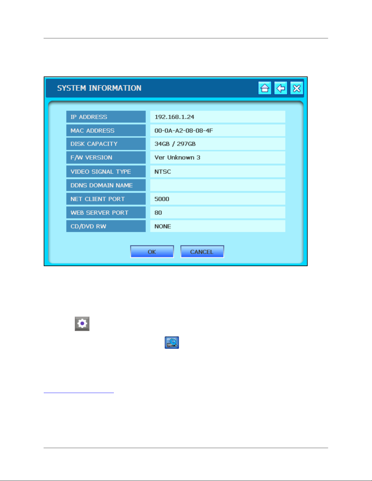
L19WD Series
How do I find my IP and MAC addresses?
The IP and MAC address of your system are necessary for DDNS setup. DDNS allows you to view and
control your system from a remote location.
To find your IP and MAC addresses:
• Press and hold the Enter button on the Front Panel for three seconds.
OR
1. Move the mouse cursor toward the bottom of the screen to open the Function Bar and
click
2. From the System Main Menu, click
.
and click System Information.
Finding Your External IP Address
If you wish to find your external IP address, you can use a third-party website such as
http://www.showmyip.com
Your external IP address can also be found within your Router settings. Refer to your router
user guide for further details.
59
Page 60
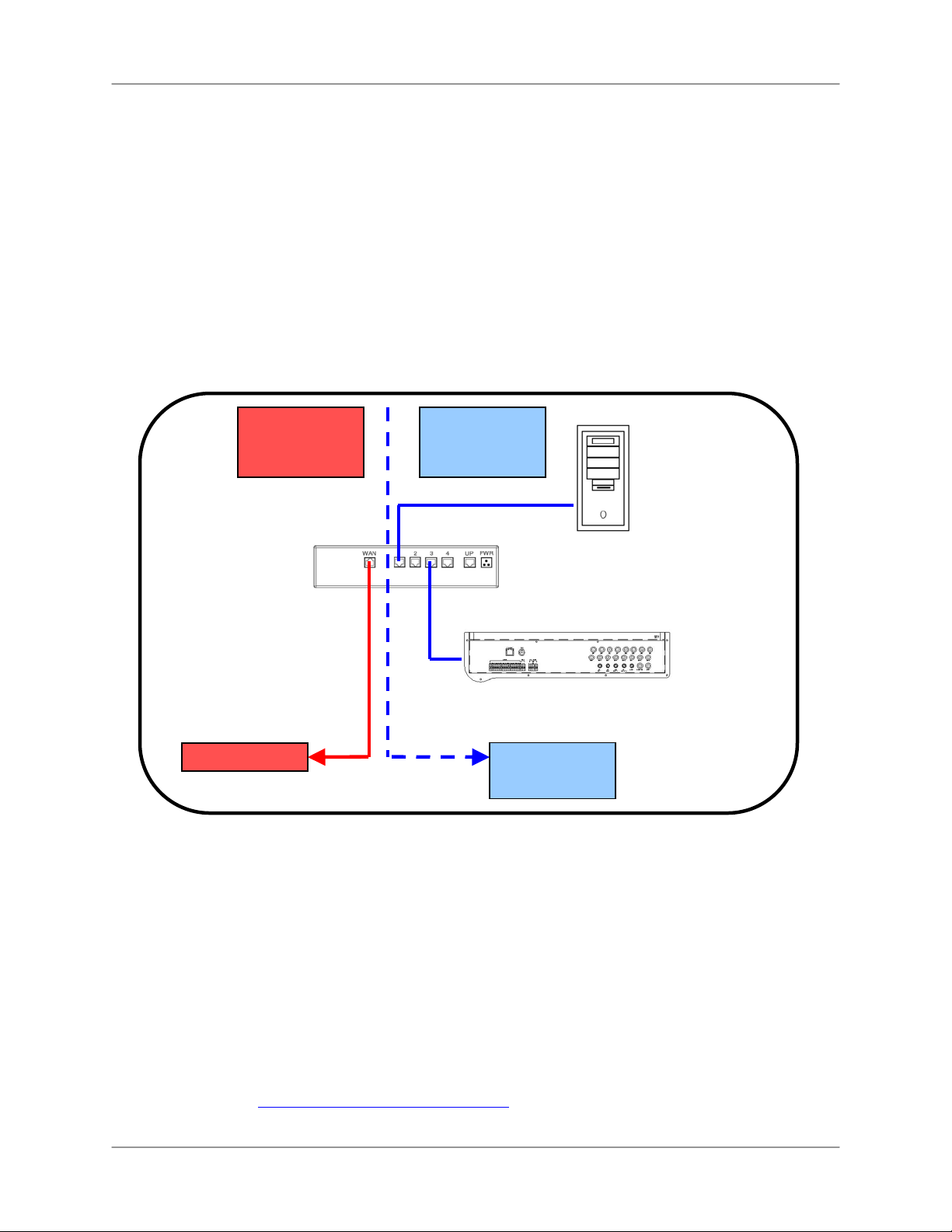
Appendix 3: Setting Up Remote Viewing
How do I enable Port Forwarding?
You need to enable port forwarding on your router to allow for external communications with
your system for the following port:
• PORT 5000
Computers, DVRs, and other devices inside your network can only communicate directly with
each other within the internal network. Computers and systems outside your network cannot
directly communicate with these devices. When a system on the internal network needs to send
or receive information from a system outside the network (i.e. from the Internet), the information
is sent to the router.
NETWORK EXAMPLE
Router
Internal IP
192.168.0.1
Router
Internal IP
192.168.0.1
PC
Internal IP
192.168.0.102
INTERNET
INTERNAL
NETWORK
SYSTEM
Internal IP
192.168.0.103
When a computer on the Internet needs to send data to your internal network, it sends this data
to the external IP address of the router. The router then needs to decide where to send this data.
This is where setting up Port Forwarding becomes important.
Port Forwarding tells the router to which device on the internal network to send the data. When
you set up port forwarding on your router, it takes the data from the external IP address:port
number and sends that data to an internal IP address:port number (i.e. Router External IP
216.13.154.34:6100 to DVR Internal IP 192.168.0.103:6100).
The instructions found online in the Router Configuration Guides will assist you in the port
forwarding configurations for a selection of different router models. Visit our Consumer Guides
Support website at http://www.lorexcctv.com/support
60
for more details.
Page 61
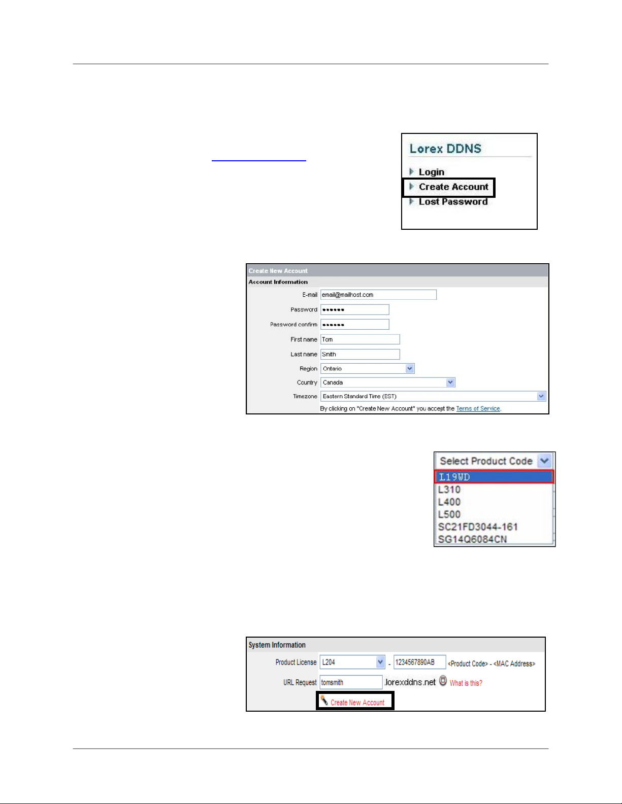
L19WD Series
How do I setup my DDNS account?
Lorex offers a free DDNS service for use with your system. A DDNS account allows you to set
up a URL (website address) that points back to your Local Network.
To setup your free Lorex DDNS account:
1. In your browser, go to www.lorexddns.net
Create Account.
2. Complete the Account
Information fields with
your personal information.
Complete the Warranty
Information with your
purchase details (optional).
3. Complete the System Information fields:
and click
• Product License: Select your product model from the
Product License drop down menu
• <Product Code> - <MAC Address>: Locate the MAC
address of your (recorded while loading the System)
• URL Request: Choose a URL for your DDNS
connection (i.e. your name, your company or business name, or anything of your
choice.)
4. Once the information has been entered, click Create New Account.
61
Page 62
Appendix 3: Setting Up Remote Viewing
(y
)
How do I setup my DDNS account? (cont’d.)
5. Your Account information will be sent to
you at the email Address you used in
Step 2.
You will need this information for remote access to your System. Record your information
below:
User Name: ____________________________________________________
*Domain Name: ____________________________________________________
Password: ____________________________________________________
* Only the first part of the Domain Name is required for setup on the System. For example, if the full
domain sent is tomsmith.lorexddns.net, the unit only requires that only tomsmith be entered.
Service Provider: dns1.lorexddns.net
User Name: tomsmith1
Domain Name: tomsmith
Password:
our password
62
Page 63
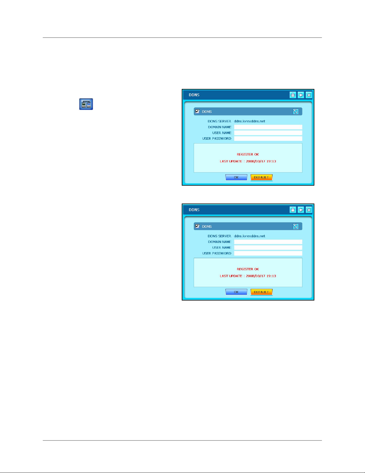
L19WD Series
How do I enable DDNS on my system?
Once the DDNS settings have been configured online, you must enter the information on the
system.
1. Open the System Main Menu and
click
and then click DDNS.
2. Check the DDNS box in the top-left
corner. From the Lorex DDNS
confirmation email, enter your
Domain, User ID, and User
Password using the Virtual Keyboard
3. Click OK to test the status of the DDNS connection.
Note: A Success message appears if the system successfully connects the DDNS Server
on the Internet. If not, check your connection and your DDNS information.
63
Page 64

Appendix 3: Setting Up Remote Viewing
How do I setup the Lorex Client Software?
The Lorex Client software allows you to remotely configure and monitor your system, and record
and playback video from a PC. Refer to the Lorex Client Software Users Manual for complete
information on using the Lorex Client.
1
2 3
4 5
6
1. CLIENT SETUP – Configure the Client software to connect to your system.
2. REMOTE VIEWER – View live video, search, and playback recorded data on your System.
3. BACKUP – Backup recorded video from your system to your PC.
4. PLAYER – Playback recorded backup video data on your PC.
5. REMOTE SETUP – Change settings on your system remotely.
6. Power – Click to exit the program
64
Page 65
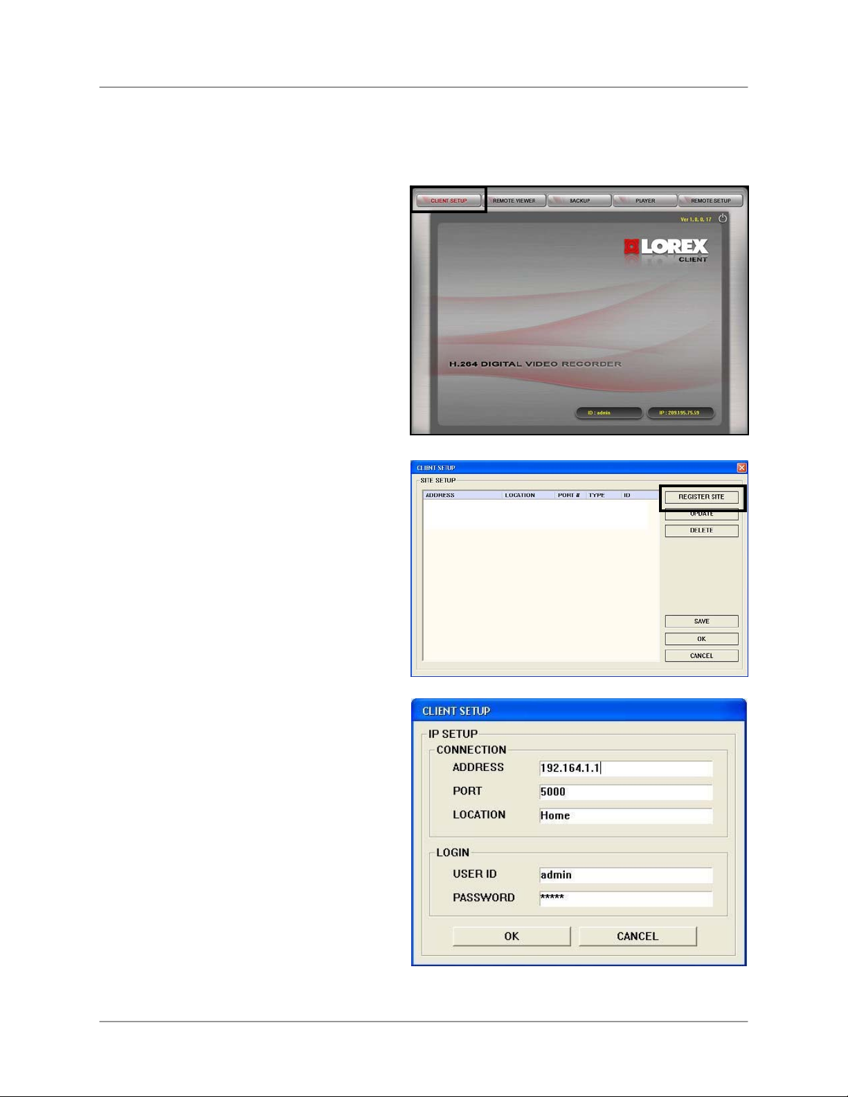
L19WD Series
Setting up the Lorex Client
You need to setup and configure the Lorex Client in order to use the Remote Viewing function of
your system. Make sure you have completed the free Lorex DDNS setup before using Lorex
Client.
To setup the Lorex Client:
1. Double-click the Lorex Client icon on
your desktop.
2. From the Lorex Client main window,
click Client Setup in the top-left
corner.
3. From the Client Setup window, click
Register Site. A new window opens
for you to input your system’s network
information.
4. Under IP Setup, enter your system’s
DDNS URL or IP address; enter 5000
in the Port field. In the Location field,
enter a name for the location of your
system (i.e. Home, Work).
5. Under Login, enter the User ID and
Password for your system and click
OK.
6. Select your newly added site and click
OK.
For complete information on using the Remote
Viewer, Player, and Backup functions of the
Lorex Client, please refer to the Lorex Client
Software Manual.
65
Page 66

Appendix 4: Listen-In Audio
Appendix 4: Listen-In Audio
Listen-in audio allows you to listen to live audio on the System one channel at a time.*
Connecting Audio Cameras
DIN only: Connect up to four 6-pin DIN camera to channels 1~4. In the Audio menu, assign
audio recording to one of these four DIN cameras.
BNC only: Connect one audio-capable BNC camera in channels 1~4 and/or one audio-capable
BNC camera channels 5~8.
DIN & BNC: Connect up to four 6-pin DIN camera to channels 1~4. In the Audio menu, assign
audio recording to one of these four DIN cameras. Connect one audio-capable BNC camera to
channels 5~8.
Note: If you are using DIN and BNC audio cameras, you must connect the BNC camera to
channels 5~8.
To enable listen-in audio:
1. Connect a BNC audio camera or DIN camera (Ch. 1~4 only) to the system.
2. Select the audio channel:
Mouse: From the Function Bar, click and then select or or click to turn the
internal speaker OFF.
Remote Control: Press the AUDIO button to switch between audio channels 1~2 or turn the internal
speaker off.
Front Panel: Press the AUDIO button to cycle between audio channels 1~2 or turn the internal speaker
OFF.
*Audio configuration varies by model:
L19WD400 – 1 Audio Channel; L19WD800 –2 Audio Channels; L19WD1600 –4 Audio Channels.
66
Page 67

L19WD Series
Appendix 5: Setting Up Motion Recording
When you first power on the system, it automatically starts recording in continuous mode. You
may wish to change this setting to better suit your security needs. One option is to have the
cameras only record when they detect motion.
You can set Motion Detection for groups of four cameras according to an hourly schedule. Use
the Motion Cell grid to apply motion detection to a specific area of the image.
To set up motion recording:
Mouse:
1. Click the ◄► to select a group of
channels (number varies depending on
your system).
2. Click
3. Click one of the tiles in the table
according to the day and hour(s) you
want to motion recording For example, if
you wanted Motion recording from
midnight to 6 AM, Monday-Friday:
i. Click
ii. Click and drag across the table from tile “MON-0” to tile “FRI-5.” The selected area
turns purple to indicate Motion recording is enabled from 12 AM to 6 AM, MondayFriday.
4. Click OK to save your settings.
Continuous & Motion
This system had an advanced recording feature where both Continuous and Motion recording
can be active at the same time:
• The system records continuously, but when it detects motion, it displays an “M” on the
pertinent channel.
• The event is logged as Motion in the system archive.
for Motion Recording.
.
• This is useful in situations where you want continuous recording, but also want to track
events for convenient and faster searching.
67
Page 68

Appendix 5: Setting Up Motion Recording
Using the Motion Cells
You can further configure Motion Detection to have the system record only when movement is
detected in a specific area of the camera image. Use this feature to mask certain areas, such as
windows and doors.
You can also set the motion cells to remove certain areas from detection, such as a heavy traffic
area, or a constantly moving piece of machinery.
To configure Motion Cell Setup:
Mouse:
1. Right-click on the screen to open
Motion Cell grid.
2. Click and drag across the screen to set
a specific motion sensitive area. Select
and Clear buttons pop-up.
Note: Active cells are clear; inactive
cells are solid grey.
Small grey squares indicate selected
squares when clicking & dragging.
To verify that motion is active, move your hand in front of the camera – the active cells turn
green.
3. Click CLEAR to disable motion
sensitivity to the selected cells. Disabled
cells turn solid grey.
4. If cells are disabled, click and drag on
cells you wish to activate and click
SELECT.
5. Right-click anywhere on the screen to
return to the MOTIOM SETUP MENU.
6. Click OK to save your settings, or click
DEFAULT to restore factory defaults.
68
Page 69

L19WD Series
Appendix 6: Using the Storage Calculator
Use the Storage Calculator included on the Software CD to determine the amount of recording
time available on your Hard Disk, according the System Record Settings.
To use the Storage Calculator:
1. Double-click Storage Calc.exe
2. Under Camera, click NTSC or PAL.
3. Depending on your system, click 4 CH, 8
CH, or 16 CH*.
Click the Quality drop-down menus to
4.
NORMAL, HIGH, or HIGHEST. Click the
FPS drop-down menus and select 3, 5, 10,
15, or 30 frames-per-second.
5. Click the HDD Size drop-down menu and
select the hard disk size of your system.
Note: If your hard drive size is not listed,
click the radio button below the drop down
menu and enter your hard drive size
manually.
6. Click HDD Check. The Storage Calculator
displays record time available
(day/hour/minute) on your best according
to the entered values. Adjust the values to
find the best configuration to suit your
security needs.
*16-channels only on L19WD1600
Final calculations – An example of final storage
calculations.
69
Page 70

Appendix 7: Replacing the Hard Drive
Appendix 7: Replacing the Hard Drive
The system comes with a pre-installed, security grade, SATA hard drive. You can expand your
system’s storage capacity by replacing the built-in HDD with a larger SATA hard drive
(maximum 1000 GB*).
Note: Before changing the hard drive, make sure to power off the system by disconnecting
the power cable from the system.
Removing the installed hard drive
To remove the installed hard drive:
1. Remove the screws from the hard
drive cover on the back of the system.
2. Carefully remove the hard drive from
the system.
3. Disconnect the cable from the hard
drive.
4. Remove the four mounting screws
and carefully slide the hard drive from
the metal casing.
Installing the new hard drive
To install the new hard drive:
1. Carefully slide the new hard drive into the metal casing (label side down), and reattach the
four mounting screws.
2. Connect the cable to the hard drive. Make sure that the cable is securely connected within
the system and to the hard drive.
3. Carefully put the hard drive in the unit. Gently slide the hard drive in place and line up the
holes for the screws.
4. Reattach the screws firmly, locking the hard drive in place. The hard drive should be flush
with the rear panel of the system.
5. Reconnect the power cable to the system.
Formatting the hard drive
You must format the new hard drive prior to recording.
If a new hard drive is detected, the system will prompt you to format the drive. If you do not
format the hard drive, it will not function properly with the system.
Note: If you format the hard drive to use in your system, it can no longer be used in a PC.
*1000 Gigabytes (GB) = 1 Terabyte (TB).
70
Page 71

L19WD Series
Appendix 8: Connecting a Spot-Out Monitor
Use the Spot port on the rear panel of the system to connect a Spot Out Monitor (not included).
Spot Out displays the camera channels in sequence. You can change the dwell time for the time
interval in the Interval menu. This is useful for a monitor in public view: you can make people
aware that they are being watched. You can also use the spot-out monitor to display
announcements or advertising. See the Lorex Client Software Manual for more details.
To change time intervals:
1. From the System Main Menu, click
2. Under Switching Interval, click ◄► to adjust the dwell time (in seconds) for the Spot
Monitor. The higher the time, the longer the image stays on screen.
3. Click OK to save your settings, or DEFAULT to restore factory defaults.
and then click INTERVAL.
Connecting an external monitor
Use the Monitor port on the rear panel of the system to connect an external monitor. Monitor-out
mirrors the entire screen image of your system. This is useful if you need to monitor the system
from a second location (e.g. a back office).
SYSTEM
SLAVE MONITOR
(NOT INCLUDED)
PUBLIC VIEW MONITOR
(NOT INCLUDED)
71
Page 72

Appendix 9: Connecting Motion / Alarm Device
Appendix 9: Connecting Motion / Alarm Device
You can enable Motion Detection and Alarm control from the System Main Menu. You can also
connect additional motion sensor devices to the system (i.e. motion sensors, door/window
sensors). Use a motion detector or sensor to send a signal to the system to begin camera
viewing and recording on the matching camera channel (when enabled in the Menu)
For example, a window sensor unit is installed on Alarm Block port #4. When this sensor
activates, the camera on CH4 will also become active (if enabled in the Alarm menu on the
system).
Installing a Sensor
To connect an external alarm sensor to the system:
1. Connect the Ground Cable to the desired Channel number – port on the rear panel.
2. Connect the Signal Cable to the desired Channel number + port on the rear panel.
3. From the System Main Menu, click
recording.
SENSOR
(Not Included)
and then click ALARM to configure alarm
SYSTEM
CH1-CH8*: Alarm input
terminals receive a
signal from a device.
*16-channel on L19WD1600.
72
GROUND
NC / NO: Alarm output
terminals send a signal
to another device
when an alarm input is
detected.
Page 73
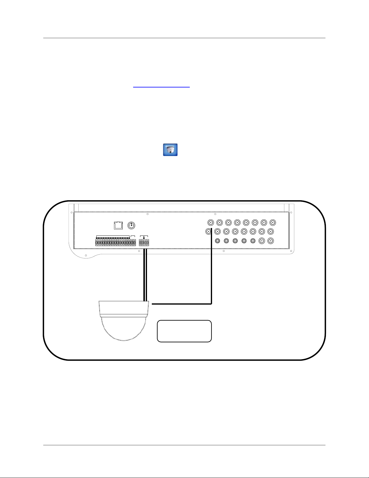
L19WD Series
Appendix 10: Connecting PTZ Cameras
You can connect PTZ cameras (not included) to the PTZ Control Block on the rear panel of the
system. You can configure the PTZ Cameras in the Camera Menu of the system. Additional
PTZ Cameras are available at www.lorexcctv.com
Installing a PTZ Camera:
1. Connect the Transmit Cable to the TX port of the PTZ block on the rear panel.
2. Connect the Receive Cable to the RX port of the PTZ block on the rear panel.
3. Connect the PTZ camera to a BNC Channel.
4. From the System Main Menu, click
and then click PTZ to configure the camera.
Note: The PTZ camera settings depend on the Type of Camera - refer to the specific
Camera Manual for your brand and model of PTZ Camera.
ETHERNET
ALARM IN RELAY PTZ RS-232
1 23 4G 56 7 8 G 9101112 G13141516G
PS/2
CH1 CH2 CH3 CH4 CH5 CH6 CH7 CH8
NO NC
D+ D- G TX RX
COM
CH9 CH10 CH11 CH12 CH13 CH14 CH15 CH16
AU1 AU2 AU3 AU4
CH1-4 CH5-8 CH9-12 CH13-16
AU OUT MONITOR SPOT
PTZ CAMERA
(Not Included)
POWER
DC12V
73
Page 74
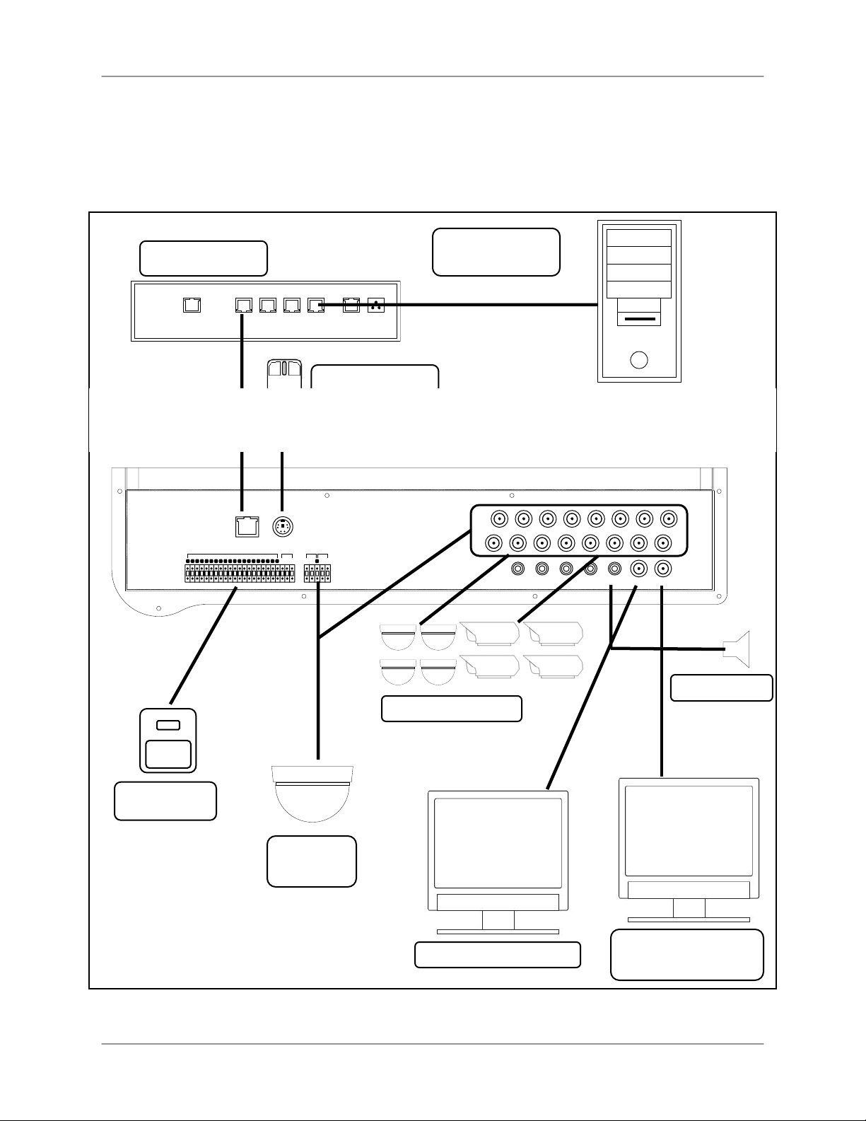
Appendix 11: Full Connectivity Diagram
†
Appendix 11: Full Connectivity Diagram
The following diagram outlines the slate of connections available for the system:
*Not included with the system.
†Configuration varies by model.
ROUTER*
WAN 1 2 3 4 UP PWR
MOUSE (PS/2)
PC for Remote
Access*
1 2 3 4 G 5 6 7 8 G 9 10 11 12 G 13 14 15 16 G
SENSOR*
ETHERNET
PS/2
ALARM IN RELAY PTZ RS-232
NO NC
D+ D- G TX RX
COM
PTZ
Camera*
CAMERAS
CH1 CH2 CH3 CH4 CH5 CH6 CH7 CH8
CH9 CH10 CH11 CH12 CH13 CH14 CH15 CH16
AU1 AU2 AU3 AU4
CH1-4 CH5-8 CH9-12 CH13-16
AU OUT MONITOR SPOT
POWER
DC12V
SPEAKERS*
SLAVE MONITOR*
PUBLIC VIEW
MONITOR*
74
Page 75
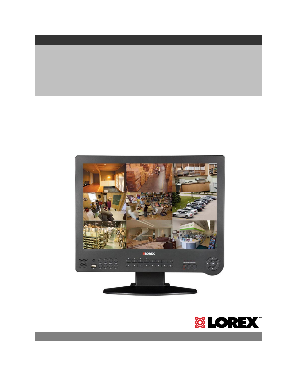
AVEC ENREGISTREUR NUMÉRIQUE INTÉGRÉ
ÉCRAN MONITEUR LCD
DE 19 POUCES LARGEUR
Instruction Manual
Version française 2.0
MODÈLES:
Série de L19WD
Copyright © 2008 Lorex Technology Inc.
Incluant le L19WD800 et L19WD1600
www.lorexcctv.com
Page 76

,
Nous vous remercions pour votre achat la système. Lorex est engagé à fournir un produit de
sécurité fiable et de haute qualité à ses clients.
Ce manuel se rapporte au suivant modèles:
Pour apprendre plus sur notre gamme complète de produits accessoires, veuillez visiter notre site
Web au :
• L19WD800 Series (8-canal)
• L19WD1600 Series (16-canal)
http://www.lorexcctv.com
ATTENTION
RISQUE D'ÉLECTROCUTION
NE PAS OUVRIR
ATTENTION: POUR RÉDUIRE LE RISQUE D'ÉLECTROCUTION,
NE PAS RETIRER LE COUVERCLE (OU L'ARRIÈRE). IL N'Y A
PAS DE PIÈCES QUI DOIVENT ËTRE ENTRETENUES À
Le symbole de l'éclair avec la pointe de flèche dans un
triangle équilatéral est conçu pour avertir l'utilisateur qu'il
y a une " tension dangereuse " non isolée dans le
produit qui a une magnitude assez importante pour
constituer un risque d'électrocution.
Le point d'exclamation dans un triangle équilatéral est
conçu pour avertir l'utilisateur qu'il y a des instructions
d'entretien (de service) et d'opération importantes dans
la littérature qui accompagne l'appareil.
AVIS : POUR EMPÊCHER LES INCENDIES ET LES CHOCS ÉLEC-
TRIQUES
ATTENTION : POUR EMPÊCHER LES CHOCS ÉLECTRIQUES, APAR-
NE PAS EXPOSER L'UNITÉ À LA PLUIE OU À L'HUMIDITÉ.
IER LA LAME LARGE DE LA PRISE AU TROU LARGE ET
L'INTÉRIEUR.
L'INSÉRER COMPLÈTEMENT.
2
Page 77
L19WD Series
Sauvegardes Importantes
En plus de l'attention soigneuse consacrée pour obtenir des normes de qualité dans le processus de
fabrication de votre produit vidéo, la sécurité est un facteur principal dans la conception de tout
instrument. Cependant, la sécurité est aussi votre responsabilité. Cette fiche énumère l'information
importante qui vous aidera à assurer l'utilisation appropriée de ce produit vidéo et de l'équipement
accessoire. Veuillez la lire soigneusement avant d'opérer et d'utiliser votre produit vidéo.
Installation
1. Lisez et suivez les instructions - Toutes les
instructions d'opération et sécuritaires doivent être
lues avant d'opérer le produit vidéo. Suivez toutes
les instructions d'opération.
2. Gardez les instructions - Les instructions
d'opération et sécuritaires doivent être gardées pour
y référer à l'avenir.
3. Obéissez les avis - Respectez tous les avis sur le
produit vidéo et dans les instructions d'opération.
4. Polarisation - N'annulez pas l'objectif sécuritaire de
la prise polarisée ou de mise à terre.
Une prise polarisée a deux lames
avec une qui est plus large que
l'autre.
Une prise de mise à terre a deux
lames et une troisième broche de
masse.
La lame large de la troisième
broche est fournie pour votre
sécurité.
Si la prise fournie ne tient pas dans votre prise,
consultez un électricien pour remplacer la prise qui
pose un obstacle.
5. Sources d'alimentation électrique - Ce produit
vidéo devrait uniquement être opéré à partir du type
d'alimentation électrique indiqué sur l'étiquette
indicatrice. Si vous ne connaissez pas le type
d'alimentation électrique où vous vous trouvez,
consultez votre détaillant vidéo ou votre compagnie
locale de services électriques. Pour les produits
vidéo conçus pour opérer à partir des batteries ou
d'autres sources d'alimentation, veuillez référer aux
instructions d'opération.
6. Surcharge - Ne pas surcharger les prises au mur ou
les rallonges, car ceci pourrait aboutir dans un risque
d'incendie ou de choc électrique. Les rallonges et les
prises AC surchargées, les câbles d'alimentation
électrique endommagés, l'isolement de fil
endommagé et les prises brisées sont dangereux. Ils
pourraient aboutir dans un choc électrique ou un
incendie. Examinez les câbles périodiquement et si
l'apparence indique des endommagements ou une
détérioration de l'isolement, faites-le remplacer par le
technicien de service.
7. Protection du fil électrique - Les fils d'alimentation
électrique devraient être acheminés pour qu'ils ne
soient pas piétinés ou pincés par des articles placés
sur ou contre eux, en faisant très attention aux
câbles à l'extrémité des prises, aux récipients
pratiques et au point de sortie du produit vidéo.
8. Ventilation - Les rainures et les ouvertures dans le
couvercle sont fournies pour la ventilation pour
assurer une opération fiable du produit vidéo et pour
le protéger de la surchauffe. Ces couvercles ne
devraient jamais être bloqués ou couverts. Ces
ouvertures ne devraient jamais être bloquées en
plaçant l'équipement vidéo sur un lit, un fauteuil, un
tapis ou toute autre surface similaire. Ce produit
vidéo ne devrait jamais être placé proche ou audessus d'un radiateur ou d'un registre de chaleur. Ce
produit vidéo ne devrait pas être placé dans une
installation intégrée comme une bibliothèque ou une
étagère, à moins que la ventilation appropriée soit
fournie ou que les instructions du fabricant pour le
produit vidéo soient suivies.
9. Attaches - N'utilisez pas des attaches à moins que ce
soit recommandé par le fabricant du produit vidéo,
car ceci pourrait causer des dangers.
10. Eau et humidité - N'utilisez pas ce produit vidéo
proche de l'eau. Par exemple, proche d'une
baignoire, d'une cuvette, d'un évier de cuisine ou
d'un bac à laver, dans un sous-sol mouillé, proche
d'une piscine, etc.
Attention: Gardez la sécurité électrique. L'équipement
opéré par les lignes sous tension ou les accessoires
liés à cette unité devrait porter
une étiquette indicatrice UL de la
marque de certification de CSA
sur l'accessoire lui-même et ne
devrait pas être modifié pour
annuler les caractéristiques
sécuritaires. Ceci devrait aider à
éviter tout danger potentiel de choc électrique ou
d'incendie. Si vous avez des doutes, contactez le
personnel d'entretien qualifié.
11. Accessoires - Ne placez pas cet équipement vidéo
sur un chariot, un support, un trépied ou une table
instable. L'équipement vidéo pourrait tomber et
causer des dommages sérieux au produit vidéo.
Utilisez ce produit vidéo uniquement avec un chariot,
un support, une table ou un trépied recommandés
par le fabricant ou vendus avec le produit vidéo.
Toute installation du produit devrait suivre les
instructions et utiliser un accessoire d'installation
recommandé par le fabricant.
3
Page 78

Sauvegardes Importantes
Entretien
12. Entretien - N'essayez pas d'entretenir cet
équipement vidéo vous-même, car ouvrir ou retirer
les couvercles pourrait vous exposer à une tension
dangereuse ou à d'autres dangers. Veuillez référer
tout entretien au personnel d'entretien qualifié.
13. Conditions qui exigent l'entretien - Débranchez le
produit vidéo de la prise du mur et référez l'entretien
au personnel d'entretien qualifié sous les conditions
suivantes.
A. Lorsque la prise ou le câble d'alimentation
électrique est endommagé.
B. Si du liquide a été renversé ou si des objets
sont tombés sur le produit vidéo.
C. Si le produit vidéo a été exposé à la pluie ou à
l'eau.
Utilisation
18. Nettoyage - Débranchez le produit vidéo de la prise
du mur avant le nettoyage. N'utilisez pas des
nettoyants liquides ou des nettoyants de bombe
aérosol. Utilisez un tissu humide pour le nettoyage.
19. Combinaison de produit et chariot - La
combinaison de vidéo et chariot devrait être
déplacée avec soin. Les arrêts rapides, la force
excessive et les surfaces inégales peuvent causer la
combinaison de chariot et de produit vidéo de se
renverser.
20. Entrée d'objets et de liquides - Ne poussez jamais
les objets pour quoi que ce soit dans des ouvertures
qui pourraient toucher des points de tension
dangereux ou des parties de " court circuit " qui
pourraient aboutir dans un incendie ou un choc
électrique. Ne renversez jamais des liquides sur le
produit vidéo.
D. Si le produit vidéo n'opère pas normalement
en suivant les instructions d'opération. Ajustez
uniquement les commandes qui sont indiquées
dans les instructions d'opération. L'ajustement
inapproprié des autres commandes peut aboutir
dans des dommages et exigera souvent du
travail extensif par un technicien qualifié pour la
restauration du produit vidéo à son opération
normale.
E. Si le produit vidéo est tombé ou si le cabinet
est endommagé.
F. Lorsque le produit vidéo présente un
changement de rendement distinct. Ceci indique
qu'il faut l'entretenir.
14. Pièces de remplacement - Si vous avez besoin des
pièces de remplacement, assurez-vous que le
technicien révise que les pièces de remplacement
utilisées ont les mêmes caractéristiques sécuritaires
que les pièces originales. L'utilisation des pièces de
remplacement spécifiées par le fabricant du produit
vidéo peuvent empêcher les incendies, les chocs
électriques ou d'autres dangers.
15. Vérifications sécuritaires - Dès que tout entretien
ou toute réparation à ce produit vidéo est complété,
demandez au technicien d'entretien de réaliser des
vérifications sécuritaires recommandées par le
fabricant pour déterminer que le produit vidéo a une
condition d'opération sécuritaire.
21. Éclairage - Pour obtenir plus de protection pour ce
produit vidéo pendant un orage électrique ou lorsqu'il
est laissé sans surveillance et sans utiliser pendant
de longues périodes de temps, débranchez-le de la
prise du mur et débranchez l'antenne ou le système
de câbles. Ceci empêchera des endommagements
au produit vidéo à cause du tonnerre et des sautes
de puissance.
16. Installation au mur ou au plafond - Les caméras
fournies avec ce système devraient être installées à
un mur ou au plafond, tel qu'indiqué dans ce guide,
en utilisant les supports d'installation fournis.
17. Chaleur - Le produit devrait être situé loin des
sources de chaleur comme les radiateurs, les
registres de chaleur, les fours ou d'autres produits (y
compris les amplificateurs) qui produisent de la
chaleur.
4
Page 79

L19WD Series
Précautions générales
1. Tous les avis et toutes les instructions de ce guide doivent être suivis.
2. Retirez la prise de la prise du mur avant le nettoyage. N'utilisez pas les détersifs liquides à bombe aérosol.
Utilisez un tissu humide pour le nettoyage.
3. N'utilisez pas cette unité dans des endroits humides ou mouillés.
4. Gardez assez de place autour de l'unité pour la ventiler correctement. Les rainures et les ouvertures dans le
cabinet d'entreposage ne devraient pas être bloquées.
5. Pendant les orages électriques ou lorsque l'unité n'est pas utilisée pendant une longue durée, débranchez
l'alimentation électrique, l'antenne et les câbles pour protéger l'unité des sautes électriques.
AVIS DE CATÉGORIE B DE LA FCC
NOTE:
Cet équipement a été vérifié et respecte les limites de Catégorie B pour les appareils numériques, selon la
Partie 15 des règlements de la FCC. Ces limites sont conçues pour fournir une protection raisonnable contre
l'interférence nocive dans une installation résidentielle. Cet équipement génère, utilise et peut radier des
fréquences d'énergie radio- électriques et, s'il n'est pas installé et utilisé selon les instructions, peut causer des
interférences nocives aux communications de radio.
Cependant, il n'y a pas de garantie que l'interférence ne surgira pas dans une installation en particulier. Si cet
équipement ne cause pas des interférences nocives à la réception de la télévision ou de la radio (ceci peut
être déterminé en allumant et en éteignant l'équipement), l'utilisateur est encouragé d'essayer de corriger
l'interférence en utilisant une des mesures suivantes:
• Réorienter ou déplacer l'antenne de réception
• Augmenter la séparation entre l'équipement et le récepteur
• Brancher l'équipement à une prise sur un circuit différent à celui dont le récepteur est branché
• Consulter le détaillant ou un technicien de télévision ou de radio spécialisé pour obtenir de l'aide
Cet équipement a été certifié et respecte les limites règlementées par FCC, EMC et LVD. Donc, il est conçu pour
fournir une protection raisonnable contre l'interférence et ne causera pas d'interférence avec d'autres appareils
employés.
Cependant, il est essentiel que l'utilisateur suive ces directives des guides pour éviter l'utilisation inappropriée qui
pourrait aboutir dans des endommagements à l'unité, dans un choc électrique et dans un incendie
De manière à améliorer les fonctions et la qualité de ce produit, les spécifications peuvent être changées sans
avis et de temps en temps.
LOREX TECHNOLOGY INC.
www.lorexcctv.com
5
Page 80

Caractéristiques de Série L19WD800
Caractéristiques de Série L19WD800
• Ecran LCD de haute définition de19 pouces avec 8 chaînes d'enregistreur numérique intégré
• Opération Pentaplex permet de Voir, Enregistrer, reproduire et sauvegarder le système
simultanément
• Enregistrement En temps réel : 240/480 FPS de Résolution CIF (8/16ch)
• Technologie de compression vidéo H.264 fournit le temps d'enregistrement plus long et la
vitesse de transmission de réseau améliorée
• le Contrôle d'Internet Lointaine (logiciel inclus) et accès du Navigateur de Web
• Navigation Conduite de souris (Souris incluse) et l'Interface d'Utilisateur Graphique
• Disque Dure de sécurité d'une grande capacité Diplômé pré installé et extensible jusqu'à 1
téraoctet (TB) * †
• Port USB pour la reproduction et transfert convenable des données critiques
• Logiciel de messagerie (inclus) permettez d'envoyer des textes et images pour un endroit lointain
• Installation amicale – le Guide de Début Rapide Facile et le support de Technologie Gratuit
Connexions :
• Jusqu’à 8 caméras (16 caméras sur L19WD1600)
• Connecteurs de Câble BNC
• Connecteurs 6 pin-DIN (seulement sur L19WD800)
• Prise d'entrée et sortie d'audio
* 1 TB = 1000 gigaoctets (le GIGAOCTET).
† Capacité d'enregistrement peut varier basé sur la résolution enregistrement et la qualité, conditions de lumière et
mouvement
6
Page 81

L19WD Series
Tableau de Contenus
Commencer...................................................................................................................................................8
Installation Fondamentale............................................................................................................................. 9
Panneau Avant............................................................................................................................................ 10
Panneau Avant (continué)...........................................................................................................................10
Panneau Avant (continué)...........................................................................................................................11
Panneau Arrière..........................................................................................................................................12
Installation du support de la caméra ......................................................................................................13
Connexions des Caméras BNC .................................................................................................................. 14
Connectant les Caméras DIN *...................................................................................................................15
Utilisation de la souris..............................................................................................................................16
Bar de Fonction ....................................................................................................................................... 17
Télécommande ...........................................................................................................................................19
Contrôle de Navigation de Menu et conseils ..............................................................................................20
Menu principal de système ........................................................................................................................21
Icônes de panneau de commande du système ......................................................................................22
Commencer le système ..............................................................................................................................23
Accéder le système ................................................................................................................................. 23
Réglage de Date & l'heure ......................................................................................................................24
Apostement d’heure ................................................................................................................................25
Éteindre le moniteur ................................................................................................................................25
Éteindre le moniteur (continué.) .............................................................................................................. 26
Modes d’affichages ..................................................................................................................................... 27
Mode en temps réel.................................................................................................................................27
Ecran complet, Quadruplé, Visualisation divisée....................................................................................28
Reproduction ...........................................................................................................................................29
Mode de recherche.................................................................................................................................30
Utilisation du Système................................................................................................................................31
Utilisation du Système.................................................................................................................................32
Configuration ........................................................................................................................................... 32
Affichage.................................................................................................................................................. 37
Gestion de HDD .....................................................................................................................................40
Caméra................................................................................................................................................... 41
Enregistrement ........................................................................................................................................ 45
Sauvegarde/ Amelioration ......................................................................................................................47
Réseau ....................................................................................................................................................48
Langue ........................................................................................................................................................52
Annexe 1 : Spécifications de système ........................................................................................................53
Annexe 2 : Exigences de logiciel de Client Lorex...................................................................................... 55
Annexe 3 : Installation de visualisation Éloignée........................................................................................ 56
Annexe 4 : Audio a l'écoute ........................................................................................................................66
Annexe 5 : Installation d'enregistrement de Mouvement............................................................................67
Annexe 6 : Utilisation de la Calculatrice de stockage.................................................................................69
Annexe 7 : Remplacement de l'Unité Dure................................................................................................. 70
Annexe 8: Connectant un Moniteur Spot Out ............................................................................................. 71
Annexe 9: Connectant l'appareil de Mouvement /Alarme...........................................................................71
Annexe 9: Connectant l'appareil de Mouvement /Alarme...........................................................................72
Annexe 10: Connectant les caméras PTZ .................................................................................................. 73
Annexe 11 : Diagramme de Connectivité complet......................................................................................74
FR
7
Page 82

COMMENCER
COMMENCER
Ce système est fourni avec les accessoires suivants
1 X SYSTÈME DE LCD VDR INTÉGRÉ
AVEC HDD PRÉ-INSTALLÉ *
(MODÈLE DE 8 CHAÎNE COMME MONTRÉE)
1 X SOURIS (PS/2)
1 1X ADAPTATEUR D'ALIMENTATION
1 X CÂBLE D'ADAPTATEUR
D'ALIMENTATION
1 X CÂBLE ETHERNET
1X MANUEL D'UTILISATEURS
1 X GUIDE DE DÉBUT RAPIDE
1 X CD DE LOGICIEL
* CAPACITÉ DE DISQUE DUR, NOMBRE DE CHAINES ET CONFIGURATION DE CAMÉRA PEUT
VARIER PAR LE MODÈLE. VEUILLEZ REFERRER À VOTRE PACKET POUR LES DÉTAILS DE
CONTENUS SPÉCIFIQUES.
VÉRIFIEZ VOTRE PAQUET POUR CONFIRMER QUE VOUS AVEZ REÇU LE SYSTÈME
AU COMPLET AVEC TOUS LES ACCESSOIRES MONTRÉES CI-DESSUS.
8
Page 83

L19WD Series
Installation Fondamentale
Faites les connexions suivantes avant de commencer le système pour la première fois.
Connectez les caméras au moniteur
Veuillez referez à la section d'Installation de Caméra
de ce manuel pour plus de détails.
ATTENTION: Testez les caméras avant de fixer en
permanence en raccordant temporairement les
caméras et les câbles à votre système.
2. Connectez le câble d'Ethernet
Connectez une fin du câble d'Ethernet (pour le
contrôle lointain) au port LAN sur une détoureuse
(non inclus) et l'autre fin au port d'Ethernet à l'arrière
du système.
3. Connectez la Souris
Connectez une souris de PS/2 au port à l'arrière du
système.
4. Connectez le câble d’alimentation
Connectez une fin de l'adaptateur d'alimentation au
moniteur et l'autre fin à une issue électrique.
Note: Le système s'allume automatiquement une fois
connecté à une source d'alimentation. Par défaut,
toutes les caméras connectées sont réglées pour
enregistrer dans le Mode Continu quand le système
5. Accès au système
Après la séquence de démarrage initial, vous aurez
besoin d'accéder le système. Pour accéder, laissez
utilisateur implicite comme ADMIN. Quittez l'espace
pour mot de passe vide et cliquez OK. Voyez la
section, pour commencer le Système pour plus de
9
Page 84

Panneau Avant
Panneau Avant
2 3 1
4
8-channel model shown
1. Détecteur IR: Reçoit le signal infrarouge de la télécommande.
2. Boutons de Fonction: L'ensemble gauche des boutons de fonction se compose du suivant:
• Menu: Appuyez pour entrer dans le Menu Principal du Système ; appuyez et
tenez pour éteindre le moniteur.
• Mode: Changement entre les affichages d'écran – l'écran complet, quadruplé et
visualisation d'écran diviser.
• Recherche: Recherche de vidéo enregistrée sur le HDD.
• Zoom: Faites un zoom/zoom en arrière d'une image en utilisant le zoom
numérique.
• PTZ: Ouvrez le menu de contrôle pour la panoramique, inclinaison, Zoom - une
caméra PTZ (non inclus) doit être connectée au système pour s'en servir le
menu PTZ.
• SEQ: Activez la fonction de séquence dans n'importe quel mode d'affichage.
• FRZ: Gelez l'image réelle.
• PIP: mode d’image en image.
3. Pavé numérique et Boutons de reproduction *:
• 1~8: Appuyez pour voir chaque chaîne du système dans le mode d'écran
complet
• 1+: Dans le Mode PTZ : faites un zoom.
• 2-: Dans le Mode PTZ : faites un zoom en arrière.
• 3+: Dans le Mode PTZ, changez les chaînes en haut
• 4-: Dans le Mode PTZ, changez les chaînes en bas.
* Seulement sur L19WD800. 16 boutons pavés numériques trouver sur le
10
Page 85

Panneau Avant (continué)
L19WD Series
5
3
3. Le Pavé numérique et Buttons de reproduction* (continué):
•
•
•
•
• Pause
•
•
Dans le Mode de reproduction, sautez pou débuter l'enregistrement
Vitesses de ralenti dans la reproduction avancé : 1/4, 1/8, 1/16 et 1/32; Augmente la
vitesse de reproduction dans la reproduction en arrière: 2X, 4X, 16X et 32X.
Reproduction en arrière; dans le Menu d'accès, aussi utilisé comme le Retour arrière pour
effacer les chiffres
Jouer
.
Arrêt
Augmente la vitesse de reproduction dans la reproduction avancé : 2X, 4X, 16X et 32X;
vitesses de Ralenti dans la reproduction en arrière: 1/4, 1/8, 1/16 et 1/32.
• Dans le Mode de reproduction, sautez vers la fin d'enregistrement
4
6
7
Dans le Mode de reproduction, réglez un signet pour la référence future dans le Mode de
•
Recherche
Indicateur LED: Quatre lumières montrent le statut du système : Alimentation, l’Enregistrement,
4.
Reproduction et Réseau
USB Port: Port USB 2.0 pour sauvegarder les données téléchargement des améliorations de
5.
micro logiciel
6. Boutons de Fonction: L'ensemble des boutons de fonction a droite se compose de la suivante :
.
.
.
• Panique: Dans un cas d'urgence, appuyez sur Panique pour l'enregistrement Continu avec
la Vidéo de Haute qualité. L'Enregistrement de Panique surpasse n'importe quel mode
d'enregistrement actif ou fonction du système
Exit: Appuyez pour sortie des menus / fonctions ou pour arrêter le la reproduction.
•
Audio: Choisissez la chaîne audio; tempérez le haut-parleur intérieur.
•
7.
Flèches de Navigation: Utilisez les flèches et le bouton d'Enter au naviguer et choisir des
options de Menu. Pendant la reproduction, les boutons de flèche exécutent le suivant:
Enter:Jouer, Reproduction en arrière, Pause; tenez pour afficher des
•
renseignements de système
Gauche: Augmentez les vitesses dans la reproduction en arrière;
•
vitesses de ralenti dans la reproduction avancé
•
Droite: Augmentez les vitesses dans la reproduction avancé ; vitesses
de ralenti dans la reproduction arrière
Haut: Augmente le volume.
•
• Bas: Réduit le volume.
.
.
11
Page 86

Panneau Arrière
Panneau Arrière
2 1 3
5
6
8 7
10
9
Port d'Ethernet : Connectez le Système à une routeur ou à un Commutateur pour les gestions
de réseau.
Souris de PS/2 : connexion dévouée pour une souris de PS/2.
Entrée de Caméra 6 pin-Din* : Chaînes1~4 pour les caméras 6 pin-Din. Les caméras avec les
connecteurs 6 pin-Din attirent l'énergie du système; les adaptateurs d'alimentation
supplémentaires ne sont pas exigés.
Entrée DC: Connecte le système à l'adaptateur d'alimentation.
Relaie/PTZ/RS-232 Bloc : Ces terminaux envoient un signal à un appareil secondaire ou
contrôle panoramique, inclinaison, caméras de zoom.
Entrée de Caméra BNC † : Ports de vidéo BNC pour les chaînes 1-8; caméras avec la
connexion BNC exigent un adaptateur d'alimentation supplémentaire.
Prises d'entrée audio RCA (2) ** : les Prises d'entrée audio pour les chaînes 1~4 et les
chaînes 5~8.
Sortie Audio : le port de sortie audio pour communiquer aux hauts parleurs, ou DVR secondaire,
ou la TV.
Sortie Moniteur : Connectant un moniteur secondaire; reflète directement les images sur écran.
Sortie Spot: Raccordez la sortie vidéo à un moniteur secondaire pour voir les chaînes de vidéos
actives en séquence. Utilisez dans les situations où le système sera dans une chambre en
arrière, mais vous voulez afficher des images au public, sois pour la modération de vol ou
les objectifs de publicité.
4
*Port 6-pin DIN seulement sur L19WD800
** Quatre prises d'entrée audio sur L19WD1600.
+16 Port BNC et 16 ports d'alarme disponibles sur L19WD1600.
12
Page 87

L19WD Series
Installation de la Caméra
Avant que vous installez la caméra *, planifiez soigneusement où et comment elle sera placé et
où vous allez passer le câble qui raccorde la caméra au DVR.
Avertissements d'installation
• Choisissez un endroit pour la caméra qui fournit une vue claire de la région que vous
voulez contrôler, qui est libre de la poussière et n'est pas en ligne d'une forte source de
lumière ou de soleil directe.
• Planifiez le trajet des câbles pour que ce ne soit pas près du pouvoir ou les lignes
téléphoniques, les transformateurs, les fours à micro-ondes ou d'autre équipement
électrique qui pourrait faire interférence avec le DVR.
• Choisissez un endroit pour la caméra qui a une température ambiante entre 14°F~113°F
(-10°c~45°c)
• si vous projetez d'installer la caméra dans un endroit qui a des conditions non
recommandées dans ce manuel, consultez un installateur professionnel et considérez
l'usage d'une couverture ou logement de caméra séparée
• Avant de commencer l'installation permanente, ayez une autre personne de tenir la
caméra pour vous pendant que vous vérifiez son exécution en observant l'image sur le
moniteur.
Installation du support de la caméra
1. Attachez le socle au plafond, mur ou d'autre surface par
la base en utilisant les vis fournies.
2. Le support de fixation doit être attaché à un appareil
structurel comme un clou mural ou un chevron de plafond
en utilisant les vis fournies.
3. Attachez la caméra au socle. Réglez l'angle de la
caméra et serrez la vis à papillon pour régler la position
Note: La caméra peut être attachée au support en
utilisant le point de vis sur le haut ou le bas (pour
maintenir l'alignement correct de la caméra). Ceci
empêche l'image d’inverser.
* Caméra ne peut pas être exactement
comme montrée
13
Page 88

Connexions des Caméras BNC
Connexions des Caméras BNC
1. Connectez le câble d'extension à la Caméra et au système:
A. Connectez le connecteur d'alimentation
Barrique à un adaptateur d'alimentation.
B. Connectez le connecteur BNC à un Port
BNC disponible sur le DVR.
C. Connectez le connecteur d'alimentation
Mâle à la Caméra.
D. Connectez le connecteur BNC à la Caméra.
2. Connectez l'Adaptateur d'alimentation à une
issue murale.
ATTENTION: Les fins du câble d'extension ne sont PAS le même - une fin a un port d'alimentation
Mâle et l'autre a un port d'alimentation Femelle. Avant de passer en permanence le Câble d'Extension
de la caméra, assurez-vous que le câble a été orienté correctement entre la caméra et l'unité.
Port d'alimentation Mâle - la fin de
port d'alimentation mâle du câble
d'Extension connecte avec la caméra
Diagramme de Connexion de la Caméra
Connect to DVR and
Power Adaptor
Le Port d'alimentation Femelle - la fin
de port d'alimentation femelle du câble
d'Extension communique à l'Adaptateur
d'alimentation.
14
Page 89

y
Connectant les Caméras DIN *
Connectez la fin femelle du câble d'extension (non inclus) à la Caméra.
* Les caméras DIN ne sont pas
incluses avec ce s
Note: Assurez que les flèches sur le
Câble de la Caméra DIN et le Câble
d'Extension DIN montrent ensemble en
raccordant le câble. Si les épingles dans
le Câble DIN sont tournées, la caméra ne
fonctionnera pas.
stème
L19WD Series
2. Connectez la fin mâle du câble d'extension à une entree de caméra DIN sur le panneau
arrière du système.
Note: La flèche sur la caméra DIN devrait faire face en haut en raccordant le câble
d'Extension DIN au système.
15
Page 90
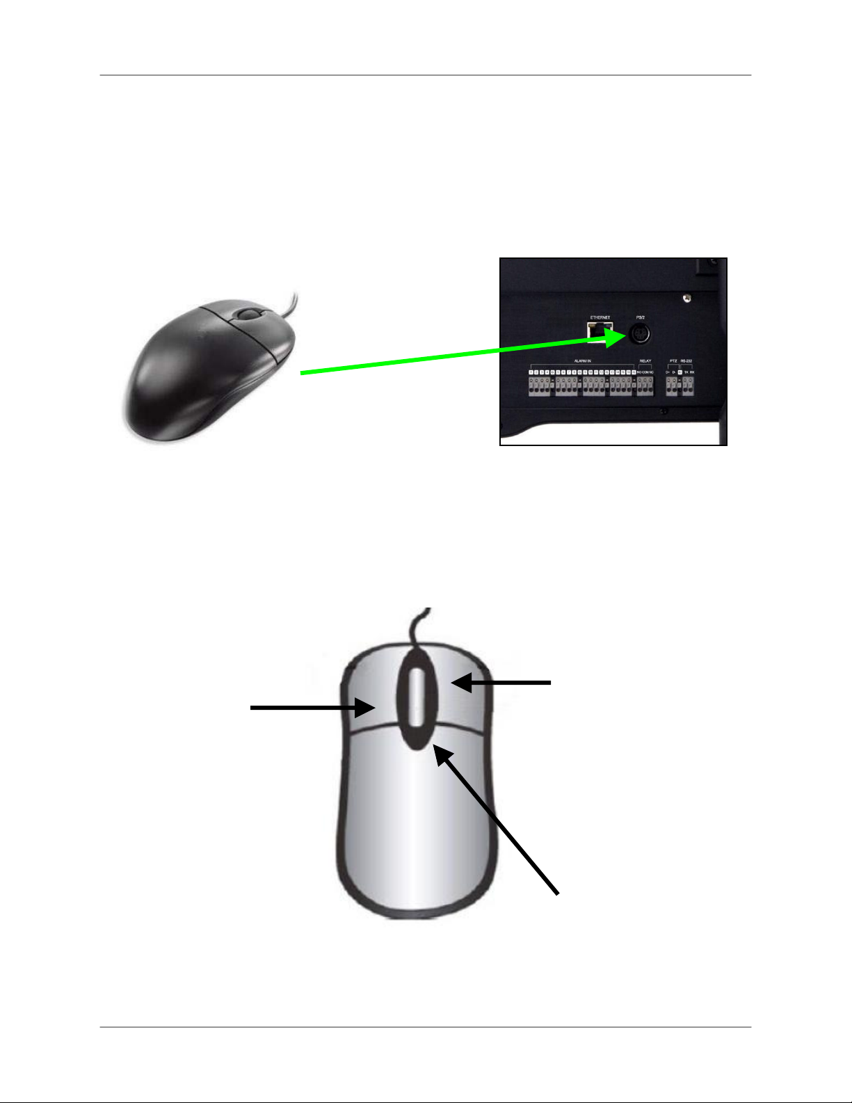
Connectant les Caméras DIN *
Contrôle de Souris
Ce système a été conçu pour utiliser une souris PS/2 ou une télécommande comme ses
méthodes primaires pour la navigation et la configuration. Connectez la souris au port de PS/2
trouvé sur le panneau arrière avant de brancher le système. Dès que l'unité a été chargée, la
souris sera reconnue par le système.
Utilisation de la souris
La souris fonctionne dans la même manière qu'une souris d'ordinateur. Utilisez le bouton droit
et gauche pour ouvrir des options de changement et des menus.
Bouton Gauche
Cliquer:
• Choisissez les
options et le changer
les valeurs dans les
menus, en mode
d'enregistrement et
mode de Recherche
• Opérez les contrôles
dans le mode PTZ
Double clique :
• Cliquez deux fois sur
une chaîne dans le
Quadruplé ou l'écran
de diviser pour voir la
chaîne en écran
complet.
Bouton Droite
Cliquer à Droite :
• S'échange entre les chaînes de
caméra actifs dans le mode
d'écran complet, ou changement
entre les groupes de chaînes
dans la visualisation d'écran
Quadruplé ou diviser
• Règlement de Mouvement :
Règle les cellules de mouvement
• Affichage D'information
Numérique (DID) : en dirigeant,
claquez a droite dans le coin
supérieur droite de l'écran pour
revenir pour le Mode réel
Roue spirale
• Dans le Mode PTZ, le Roulez
en haut pour faire un zoom,
Roulez au bas pour faire un
zoom en arrière.
16
• Change des valeurs dans de
certains menus.
Page 91
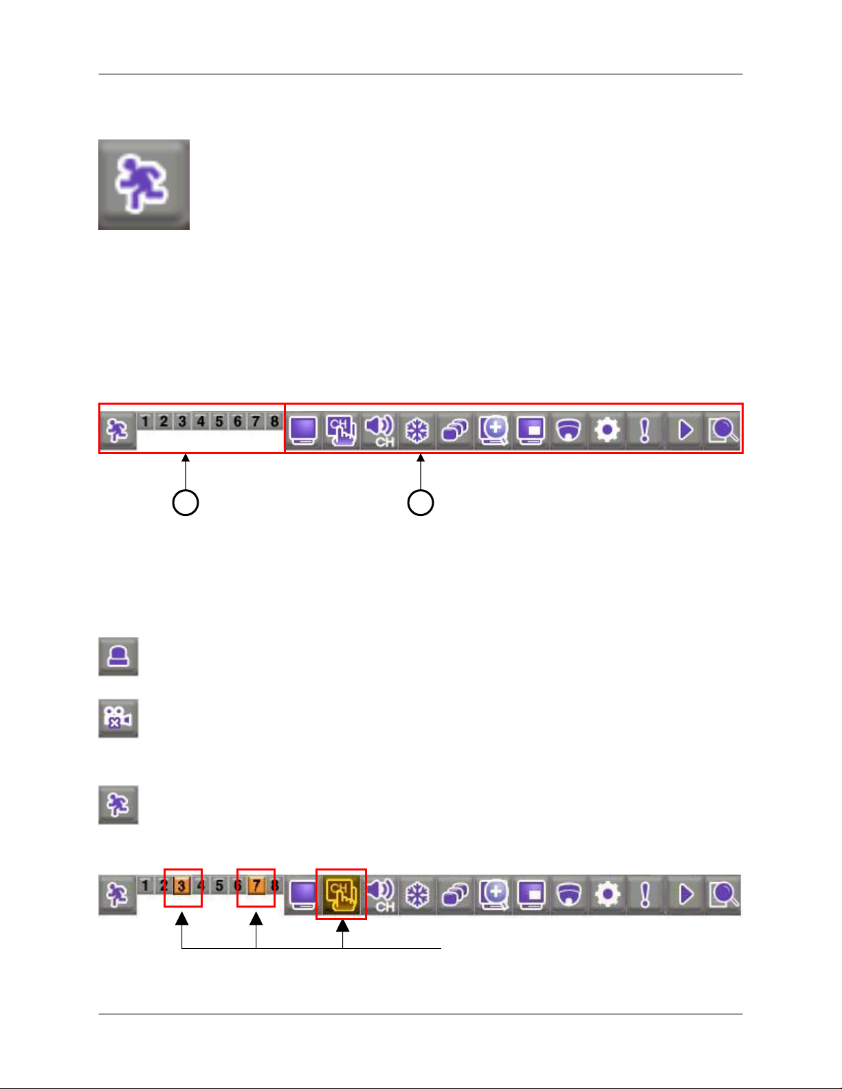
Bar de Fonction
En utilisant la souris, le Bar de Fonction est l'instrument sur écran primaire pour
accéder et aux cadres de système changeants et les configurations.
Pour ouvrir le Bar de Fonction :
Souris:
Le Bar de Fonction contient deux composantes principales :
1. Chaîne d'affichage
2. Icônes de Fonction
• Déplacez le curseur au bas de l'écran
L19WD Series
Télécommande:
• Appuyez sur le bouton FUNC
1
2
Affichage de chaîne
Cliquez sur l'icône pour voir le statut de chaque caméra dans l'Alarme, la Perte de came, ou
Mouvement.
Alarme – enregistrement de Panique. L'Enregistrement de Panique surpasse tous les
autres modes d'enregistrement du système.
Perte de came – la caméra est devenue débranchée, ou le signal a été perdu
Mouvement – l'Enregistrement est déclenché par la détection de mouvement.
Exemple de perte de caméra:
Le Bar de Fonction montre que les
caméras 3 et 7 ont été débranchées.
17
Page 92

Connectant les Caméras DIN *
Icônes de Fonction
Icône Description
AFFICHAGE – Échange entre l'Écran complet, Quadruplé et les visualisations d'écran diviser.
CHA
ÎNE– Cliquez pour voir n'importe quelle chaîne dans le mode d'Écran complet.
AUDIO – Choisissez une chaîne audio parmi 1~4; cliquez OFF pour d'éteindre l'audio.
GELER – Gel l'image. Appuyez sur ESC pour annuler le Mode de Gel.
SÉQUENCE – Active le Mode de séquence pour les caméras connectées seulement. Vous
pouvez régler la visualisation d’affichage (l'Écran complet, Quadruplé, 9 Division) avant
d'activer le Mode de séquence.
ZOOM – Dans le mode réel, l'image se zoom en 2X dans la visualisation d'Écran complet.
Cliquez et tirez la petite boîte bleue dans le coin droite au fond de l'écran pour voir d'autres
régions de l'image ou utiliser les boutons de Navigation sur la Télécommande.
PIP – Active la fonction image en image (PIP).
Une chaîne apparaît sur l'Écran complet, pendant qu'un autre apparaît dans une petite fenêtre
d'insert. Le petit écran s'affiche dans l'ordre selon un intervalle programmé.
PTZ – Ouvre le panneau de contrôle de panoramique, inclinaison, zoom (PTZ).
Note: Les caméras de PTZ ne
sont pas incluses avec ce
système. Voyez l'Appendice 10
pour plus de détails.
18
o NEAR
o FAR
o OPEN
o CLOSE
o SET
Faire le point de près
Faire le point de loin
Ouvrir l'Iris
Fermer L'Iris
programmer le Réglage
o GO TO
o AUTO
o PRESET
Allez au réglage
Scrutation automatique
Entrez le numéro présent
RÉGLAGES – Ouvre le Système du panneau de commande (Accès: ADMIN; quittez l'espace
de mot de passe vide). Voyez l'Utilisation du Système : la Configuration pour plus de détails
pour changement de votre mot de passe.
PANIQUE – En cas d'urgence, Cliquez pour commencer l'Enregistrement de Panique.
apparaît sur toutes les chaînes; le système enregistre dans le mode Continu à la plus haute
qualité vidéo. Appuyez de nouveau pour annuler.
REPRODUCTION– cliquez pour reproduire la vidéo enregistrée. Le panneau de control des
animations soutiens, joue, pause, et suivant/précédent
RECHERCHE – Ouvre le menu de Recherche; Scrute pour la vidéo enregistrée par
Date/Chronomètre, l'Événement, ou le Signet.
Page 93
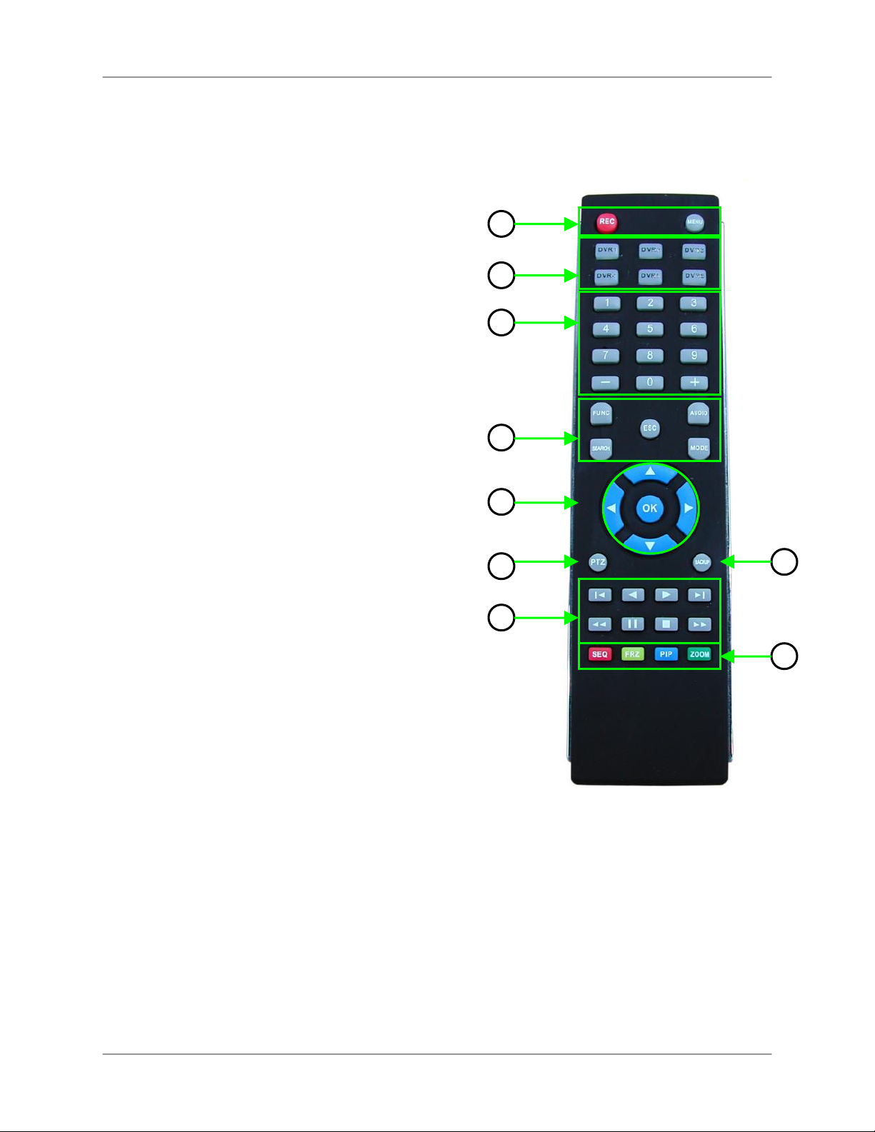
Télécommande
Énuméré ci-dessous est une référence rapide pour la Télécommande.
1. REC: Appuyez sur REC pour commencer
l'enregistrement de Panique sur le DVR.
MENU: Appuyez pour ouvrir le Menu Principal du
Système
2. DVR 1-6 – Choisissez la carte d'identité DVR pour
contrôler des systèmes multiples.
3. Clavier numérique, – + – Appuyez sur les boutons
numérique pour naviguer par les chaînes individuels
dans le mode d'écran complet *; Appuyez–, pour
naviguer par les modes d'affichage: l'écran complet,
quadruplé, huit.
4. FUNC – Ouvre et ferme le bar de contrôle de Fonction.
RECHERCHE: Ouvre le menu de recherche.
ESC: Menus de sorties, fonctions; arrêt de reproduction.
AUDIO: Change les entrée audio (Ch. 1~4) ou tempérer
l'haut parleur intérieur.
MODE: Change l'affichage d'écran : l'écran complet,
Quadruplé et visualisation d'écran diviser.
5. ◄▲▼►, OK (Boutons de Navigation) – Naviguez a
travers les options de menu et les valeurs de
changement. Opérez les fonctions de PTZ.
6. PTZ – Ouvre le menu PTZ.
7. Contrôles de reproduction –
Appuyez pour débuter l'enregistrement
o
o Vitesses de ralentissement dans la reproduction
Avancé : 1/4, 1/8, 1/16 et 1/32; Augmente la
vitesse de reproduction la reproduction en arrière :
2X, 4X, 16X et 32X.
o
Reproduction en arrière
o Reproduction en avant
o Pause
Arrêt
o
Augmentez la vitesse de reproduction dans la
o
reproduction Avancé : 2X, 4X, 16X et 32X;
Ralentie la vitesse de reproduction arrière: 1/4,
1/8, 1/16 et 1/32.
o
Appuyez pour terminer l'enregistrement.
8. SAUVEGARDER – Ouvre le menu de Soutien d'USB.
9. SEQ, FRZ, PIP, ZOOM –
o SEQ Automatiquement navigue les chaînes en
séquences. Choisissez l'écran complet, Quadruplé,
ou visualisation en Huit vue avant d'appuyer sur
SEQ.
o FRZ le mode d'écran complet, Gèle l'image;
appuyez sur Esc. pour annuler. Dans le Quadruplé
et la visualisation en Huit, activez les
caractéristiques de gel, appuyez ensuite sur le
bouton numéral correspondant pour congeler
l'image; appuyez sur Esc pour annuler.
o PIP Commence la visualisation d'image en image.
o ZOOM Active l'écran complet en mode de zoom.
Utilisez des flèches de navigation pour scruter
l'image rapidement; appuyez sur ESC pour annuler.
L19WD Series
1
2
3
4
5
6
7
*L19WD1600 seulement: 0+0 = 10,
0+1 = 11, etc.
8
9
19
Page 94
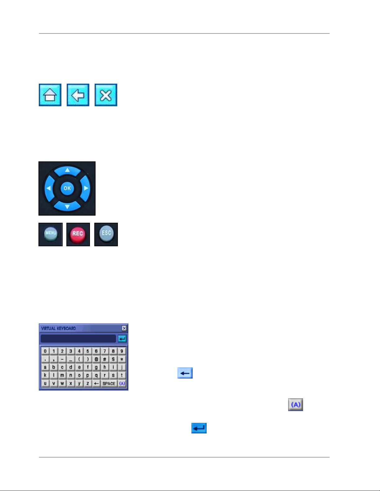
Contrôle de Navigation de Menu et conseils
Contrôle de Navigation de Menu et conseils
Utilisation des Icônes de Navigation
Utilisez les Icônes de Navigation en naviguant les menus de système.
• MAISON Cliquez sur l'Icône de maison "Home"pendant que vous
été dans n'importe quel menu pour retourner au Menu principal de
Système.
• RETOUR Cliquez sur l'Icône de retour "Back" pour retourner au
menu précédent.
• SORTIE Cliquez sur l'Icône de Sortie "Exit" pour sortir des menus.
Utilisation des boutons de Navigation
En utilisant la télécommande, les boutons de Navigation sont la
façon primaire pour se déplacer entre les menus du système.
• ◄► Appuyez les boutons fléchés de Gauche et à droite pour
choisir les options différentes dans les menus.
• ▲▼ Appuyez sur les boutons fléchés du haut et de bas pour
changer des valeurs dans les options. Ces boutons peuvent
aussi choisir les options de menu différentes dans certains
menus.
• OK Appuyez sur le bouton d’OK pour changer les valeurs
d'option et confirmer les sélections.
• MENU Appuyez le bouton de “Menu” pour ouvrir le Menu
principal du Système ; vous devez en premier entrer votre nom
d'utilisateur et le mot de passe.
• REC Dans une urgence, appuyez sur le bouton
d'enregistrement “Rec” pour commencer l'Enregistrement de
Panique ; Appuyez encore une fois pour annuler.
• ESC Appuyez le bouton "escape" pour fermer les fichets et les
menus.
Utilisation du Clavier virtuelle
Vous devez utiliser le Clavier virtuelle pour changer les mots de
passe d'utilisateur et éditer les noms des caméras.
1. Cliquez pour effacer le mot de passe implicite ou le titre
de la caméra
2. Entrez un nouveau mot de passe ou un titre de caméra en
.
20
utilisant le clavier alphanumérique. Appuyez sur
changer le caractère.
3. Appuyez sur
ferme le Clavier virtuelle.
pour sauvegarder des changements et
pour
Page 95
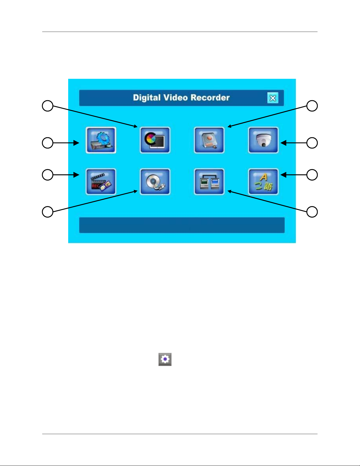
L19WD Series
Menu principal de système
2 3
1
5
6
1. CONFIGURATION
2. AFFICHAGE
3. GESTION DE HDD
4. CAMÉRA
4
7
8
5. ENREGISTREMENT
6. SAUVEGARDER/AMELIORER
7. RÉSEAU
8. LANGUE
Pour ouvrir le menu principale du système:
Souris:
• De la Barre de Fonction, Cliquez .
Télécommande:
• Appuyez MENU.
Note: Vous devez signer au système avant que vous aller pouvoir accédé le Menu principal
du Système.
21
Page 96

Menu principal de système
Icônes de panneau de commande du système
Icône Description
CONFIGURATION – Règle la Date/Temps, Mots de passe, Autorité d'utilisateur,
Audio, Information de Système, et restaure les défauts d'usine.
AFFICHAGE – Change les cadres d'affichage, ajuste la résolution, et rendre capable
le Mode DID (Affichage d'Information Numérique).
GESTION D’HDD– format Le disque dur rend capable/ infirme formatage du disque.
CAMÉRA – Change le titre de la caméra, ajuste la couleur, règle la caméra, alarme,
mouvement, réglages de PTZ, et règle le surgissant des événements
ENREGISTREMENT – Configure le règlement d'enregistrement, Schedule, et
réglages des jours fériés.
SAUVEGARDER/AMELIORER – Sauvegarde des données à l'appareil USB de
stockage ; l'amélioration de microprogramme.
22
RÉSEAU – Ajustez les réglages et connexions d’IP, et activer/de activer le DDNS.
LANGUE – Change la langue de système à l'Anglais, Français, ou Espagnol
Page 97

L19WD Series
Commencer le système
Une fois vous avez fait toutes connexions au système et l'avez alimenté , vous devez signet au
système et réglez la date et l'heure.
ATTENTION: Quand vous signez pour la premièrement fois au système, gardez
ADMIN comme votre nom d'utilisateur et laissez la critère mot de passe vide. Voyez
Utilisation de Système : la configuration ou changement de mot de passe pour plus
de détails.
Accéder le système
Pour accéder le système:
Souris :
1. Déplacez le curseur vers le bas de l'écran pour ouvrir la Barre de Fonction.
2. De la Barre de Fonction, le cliquez .
3. Choisissez votre nom d'utilisateur et le mot de passe et cliquez OK.
Télécommande:
1. Appuyez sur le bouton de MENU.
2. Utilisez les Boutons de Navigation et le Pavé numérique pour choisir votre nom
d'utilisateur et votre mot de passe.
3. Choisissez OK.
Note: Vous devez signet quand vous accédez les menus importants comme suivant:
o Recherche
o PTZ
o Eclaircissement HDD
o Sauvegarde
23
Page 98

Commencer le système
Réglage de Date & l'heure
ATTENTION: Vous devez régler la date et l'heure avant d'installer une Schedule
d'enregistrement sur le système. Voyez Utilisant le Système : Enregistrer pour plus de
détails sur installation d’un plan d'enregistrement.
Réglage de la date et l'heure:
Souris:
1. Du Menu principal de Système, cliquez
.
2. Du menu de Configuration, cliquez DATE/HEURE.
3. Cliquez + /- changer le FORMAT D'AFFICHAGE, ZONE HORAIRE et la Date et l'heure pour le
système. Cochez la boîte DST pour rendre capable l'Heure d'été.
4. Cliquez OK pour épargner votre réglage ou cliquez DEFAULT pour restaurer les défauts d'usine.
5. Cliquez
pour sortir
Télécommande:
1. Appuyez sur le bouton de MENU et signez au système.
2. En utilisant les boutons de navigations, sélectez
après sélectez DATE/HEURE.
Utilisez◄►pour navigué entre les options de menu. Utilisez ▲▼pour changé les réglages individuels.
3. Choisissez le FORMAT D’AFFICHAGE, ZONE HORAIRE et la Date et l'heure pour le système.
Cochez la boîte DST pour rendre capable l'Heure d'été.
4. Cliquez OK pour épargner votre réglage ou cliquez DEFAULT pour restaurer les défauts d'usine.
5. Appuyez sur le bouton ESC pour sortir.
24
Page 99

L19WD Series
Apostement d’heure
Quand vous changez la date et l'heure après avoir enregistré des données vidéo. Un fichet
surgissant apparaîtra vous informant que la vidéo enregistrée avant le changement d'heure
gardera l'apostement d'heure original.
Le même s'applique a des changements à l'heure d'été (DST).
Éteindre le moniteur
• Du panneau d'avant, appuyez et tenez le bouton de
MENU pour 3 secondes.
• Le système continue à enregistrer pendant que le
moniteur est éteint. Les lumières LED restent allumer sur
le panneau d'avant. Ceci est utile à déguiser le fait que le
système est un moniteur de sécurité.
• Appuyez le bouton de MENU encore pour allumer le
moniteur de nouveau.
Note: Appuyant seulement le bouton de MENU
allumera le moniteur de nouveau.
25
Page 100

Commencer le système
Éteindre le moniteur (continué.)
Le moniteur peut être réglé aussi dans le mode d'economiseur d'ecran:
1. Du Tableau de commande de Système
cliquez
et après cliquez VGA.
2. Cliquez l’économiseur d’écran sur ON.
3. entrez l'heure D' ÉTEINT D’ ÉCRAN et
ALLUMAGE D’ ÉCRAN. Le système utilise
l'horloge de 24 heures.
4. Cliquez OK pour économiser vos réglages
ou cliquez sur DEFAULT pour restaurer les
défauts d'usine.
26
 Loading...